Wenglor B50 Operating Instructions Manual
Smart camera/vision-sensor/1d-/2d-code-scanner/ocr reader
Hide thumbs
Also See for B50:
- Operating instructions manual (35 pages) ,
- Quick start manual (11 pages)
Table of Contents
Advertisement
Quick Links
Advertisement
Table of Contents

Related Manuals for Wenglor B50


Summary of Contents for Wenglor B50
- Page 1 Smart Camera / Vision-Sensor / 1D-/2D-Code-Scanner / OCR Reader Operating Instructions Translation of the Original Operating Instruction Subject to change without notice Available as PDF version only Version: 1.4.0 Status: 17.02.2017 www.wenglor.com...
-
Page 2: Table Of Contents
Table of Contents 1. Use for Intended Purpose ..................8 2. Safety Precautions ....................8 3. Approvals and protection class ................8 4. Technical Data ......................9 4.1. Available weQube Sensor Types ......................9 4.1.1. Sensors with Monochrome Image Chip ..................9 4.1.3. - Page 3 6.8.2.3. MAC Address ........................ 31 6.8.2.4. Network Reset ....................... 31 6.9. Language .............................. 31 6.10. Info ............................... 32 6.11. Restart ..............................32 6.12. Reset..............................32 6.13. Password ............................. 33 6.14. Status Information ..........................33 7. Installing and Updating the Software ..............34 7.1.
- Page 4 10.2.4. Image Area ..........................66 10.2.5. The Status Bar .......................... 66 11. Software Module ....................67 11.1. Application Module ..........................67 11.1.1. Overview ........................... 67 11.1.2. Setting Parameters ........................67 11.2. Camera Device Module ........................68 11.2.1. Overview ........................... 68 11.2.2.
- Page 5 11.8.3.4. Saturation ........................110 11.9. Module Cluster ..........................110 11.9.1. Overview ..........................110 11.9.2. Settings ........................... 111 11.9.3. Configuration .......................... 112 11.9.3.1. Cluster List......................... 113 11.10. Module Measure ..........................113 11.10.1. Overview ..........................113 11.10.2. Settings ..........................114 11.10.2.1. Find Line ........................115 11.10.2.2.
- Page 6 11.14.3.9. Teaching Characters In ................... 149 11.15. OCR-Tip ............................150 11.15.1. Basic Character Geometry ....................151 11.15.1.1. Examples ......................... 151 11.15.2. Size of the ROI ........................151 11.15.2.1. Examples ......................... 152 11.15.3. Background .......................... 152 11.15.4. Contrast ..........................152 11.15.4.1. Examples ......................... 153 11.16.
- Page 7 11.24.1. Overview ..........................175 11.24.2. Settings ..........................175 11.24.3. Configuration ........................175 11.24.3.1. RS-232 ........................176 11.24.3.2. Industrial Ethernet ....................177 11.24.3.3. UDP ......................... 179 11.24.3.4. FTP or SD Card ....................... 180 11.24.4. Error Handling ........................181 11.25. Module Statistics ..........................182 11.25.1.
-
Page 8: Use For Intended Purpose
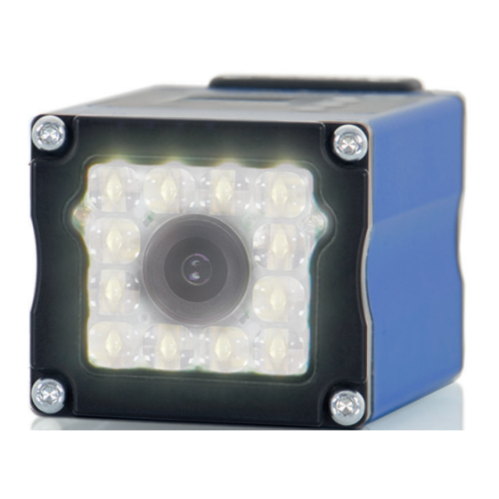
1. Use for Intended Purpose The wenglor weQube is an optoelectronic sensor which is used for contactless inspection of specific objects. The sensor unites a camera unit, illumination, optics with auto-focus and an analysis module in a single hous- ing. The sensors work with a CMOS color or monochrome image sensor. -
Page 9: Technical Data
4. Technical Data 4.1. Available weQube Sensor Types 4.1.1. Sensors with Monochrome Image Chip Light Sensor type White Light Red Light Connection B50S002 B50S003 Ethernet B50S005 B50S006 weQube Vision B50S101 B50S102 Industrial Ethernet B50S104 B50S105 Ethernet C50C001 C50C002 C50C003 weQube Decode Industrial Ethernet C50C100 C50C101... -
Page 10: Sensors With Color Image Chip And Autofocus
4.1.3. Sensors with Color Image Chip and Autofocus Light Sensor type White light Connection B50S001 Ethernet B50S004 weQube Vision B50S100 Industrial Ethernet B50S103 Ethernet B50M001 weQube Industrial Ethernet B50M100 4.1.4. Sensors with color image chip and C mount Sensor type Connection Monochrome B50S011... -
Page 11: List Of Technical Data
4.2. List of Technical Data Optical Characteristics ≥ 20 mm (weQube with auto-focus) Working range Resolution 736 px × 480 px Field of vision See “Range of Vision Table” Image chip See section 4.1 on available sensor types Type of light See section 4.1 on available sensor types ≤... -
Page 12: Connection Diagrams
Signal Output White Contactor Monitoring Pink Ethernet Gigabit bidirect. data line (A-D) Encoder A/A (TTL) Green/Yellow Encoder 0-pulse 0-0 (TTL) Encoder B/B (TTL) Note: If you use wenglor connection cables, you’ll find the corresponding wiring diagram in section 5.3.2.1. Technical Data... -
Page 13: Housing Dimensions
4.4. Housing Dimensions 4.5. Control Panel Up key Enter key Down key Display Smart Camera / Vision-Sensor / 1D-/2D-Code-Scanner / OCR Reader... -
Page 14: Installation And Connection
The sensor must be protected against mechanical influences. Install the weQube such that its installation position cannot be inadvertently changed. The wenglor mounting system is recommended for installing the sensor. It must be assured that the mounting screws have a thread engage- ment length of 5 to 7 mm. - Page 15 Connector Cables Connector Cables Connection Cable Connection Cable M12, 12-pin to open end M12, 8-pin to RJ45 ZDCL001 (straight) ZC1V001 ZDCL002 (straight) ZAV50R502 ZDCL003 (straight) 10 m ZC1V002 10 m ZDCL004 (angled) ZDCL005 (angled) ZDCL006 (angled) 10 m Interface Cable M12, 12-pin to RS-232 ZDCG002 Mounting System...
-
Page 16: Accessory Products
5.3. Accessory Products 5.3.1. Matching Mounting Technology ZMBID1202 Mounting System ZMWZF0001 Mounting Bracket for illumination technology 5.3.2. Matching Connection Technology 5.3.2.1. Connector Cables ZDCL001 M12×1 connector cable, 12-pin, 2 m, straight ZDCL002 M12×1 connector cable, 12-pin, 5 m, straight ZDCL003 M12×1 connector cable, 12-pin, 10 m, straight ZDCL004 M12×1 connector cable, 12-pin, 2 m, angled... -
Page 17: Connecting Module
5.3.2.3. Connecting Module ZDCG001 M12×1 connecting module, 12-pin to trigger, illumination 5.3.2.4. Interface Cable ZDCG002 M12×1 interface cable, 12-pin to RS-232 Smart Camera / Vision-Sensor / 1D-/2D-Code-Scanner / OCR Reader... -
Page 18: Led Display
5.4. LED Display The LEDs on the back of the weQube indicate the following (rear view of the weQube with display at top): Profinet Function Communication status Module status Link/act LED Designation Status Function CS (communication status) Connection (AR) established with (only available with Profinet controller devices) -
Page 19: Cable Connection
description Status Function NS (Network status) No IP address green CIP connection Blinking green IP configured, no CIP connection Duplicate IP address Blinking red CIP connection Timeout MS (Module status) green Device works Blinking green Standby Fatal error Blinking red Device error No Ethernet device connected green... -
Page 20: Adjusting Sensor Network Settings Automatically Via Dhcp Server
Install the associated device-specific electronic description file to the hardware manager (e.g. the GS- DML for Profinet). The required file can be downloaded from www.wenglor.com Product World Product search (Order No.) Download. Explanations regarding the electronic description file and its layout are included in the comprehensive operating instructions in PDF format. -
Page 21: Default Settings
5.6. Default Settings weQube Teach + Number of frames Intensity Screensaver Display Mode Text Serial Baud rate 115.200 DHCP IP Adress 192.168.100.001 Interface Subnet mask 255.255.255.000 Ethernet MAC Adress See label on Sensor Std. gateway 192.168.100.254 TCP/IP Port 32001 Language English Enable Disable... -
Page 22: Functions Description, Oled Display
6. Functions Description, OLED Display Teach-In 1 Teach-In 2 Teach-In 3 <T> for teach-in Teach-In Teach-In 4 Teach-In 5 Teach-In 6 Image Count Number of frames: 0 - 1000 Teach+ Start Minimum Normal Maximum Rotate Power Save Display Intensity Screensaver Mode Network Text... -
Page 23: Run
The first time the sensor is started and after each reset, language selection and the assistant appear at first (see section 6.9). Language English Deutsch Français Navigation with the keys: p : Navigate up q : Navigate down. 8 : Enter key You can switch to the configuration menu by pressing any key. -
Page 24: Teach-In
6.2. Teach-In Subsequent sensor teach-in is possible with the display. Up to six teach options can be taught-in in this way. The parameters which are assigned to the memory locations is determined by means of the PC software. Upon delivery, no parameters are assigned to the teach-in memory locations. Teach-In Select memory location for teach-in Teach-In 1... -
Page 25: Display
6.4. Display Various changes can be made to the settings at the display in order to simplify operation of the sensor. Display Display settings Rotate Rotate: Rotate the display 180°. The display is rotated 180° by pressing Intensity the 8 key. The display can be returned to its original position by pressing the same key once again. -
Page 26: Mode
6.4.2. Mode The weQube display is equipped with various display modes which can be used as default settings for the run mode. Mode Selection of the display for the “Run” mode O Network Network: The statuses of the various networks are displayed in the “Run” O Text mode (TCP/IP, FTP, Profinet). -
Page 27: Assistant
6.5. Assistant The assistant is started automatically when the sensor is switched on for the first time, and each time the sensor settings are reset. However, it can also be started manually in order to simplify project selection and sensor configuration. -
Page 28: Projects
Exiting the assistant You have com- If you want to run the assistant again, press the “Y” key. pleted all of the steps offered by After pressing the “N” key, the assistant is exited and the display is switched to the the assistant. -
Page 29: Selecting The Start Project
6.6.3. Selecting the Start Project Set start project Selecting the start project Project_1 You can select a project from the project list in the “Set start project” menu, which is then selected automatically when the sensor is started. Project_2 Project_3 ... -
Page 30: Ethernet
6.8.2. Ethernet Settings for the Ethernet connection Ethernet DHCP DHCP: Display: DHCP on or DHCP off IP address IP address: Display of the selected IP address Subnet mask Subnet mask: Display of the selected subnet mask Std. gateway Std. gateway: Display of the selected standard gateway MAC address MAC address:... -
Page 31: Mac Address
6.8.2.3. MAC Address MAC Address Displaying the MAC Address The sensor’s unchangeable MAC address is displayed. 54:4a:05:00:08:04 After pressing the key, the display is returned to the Ethernet network menu. 6.8.2.4. Network Reset Network reset Resetting the Network Configuration Press The network configuration can be reset by pressing “R”. -
Page 32: Info
6.10. Info Display of sensor information Info Sensor type Sensor type, product version, serial number and status are displayed in the informa- B50S001 tion menu. These entries play an important role in the event that technical problems should oc- Product version cur, and when contacting Technical Support with questions. -
Page 33: Password
Be sure to make a note of the new password before exiting the “change password” function! If the password is forgotten, it must be overwritten with a master password. The master password can be requested by e-mail from support@wenglor.com. 6.14. Status Information In addition to status information and warnings in the “Info”... -
Page 34: Installing And Updating The Software
1. Uninstall current weQube software using the Software function in the Control Panel. 2. The latest software version is available from the download area at our website: www.wenglor.com 3. The new software can be installed as described in section 7.2 Before updating the software, make sure that the firmware has been updated to the most recent version. -
Page 35: Updating The Firmware
The most up-to-date version of the firmware can be downloaded from our website at: www.wenglor.com Product World Product search (Order no.) Download Software. Note: When the firmware is updated, the associated PC-software should be updated at the same time (see section 7.3). - Page 36 All selected projects are converted to the target version. The version designation is added to the previous pro- ject name for the converted projects. And thus Trainingsdemo.w_p becomes Trainingsdemo_V1.3.w_p. The status display for the individual projects indicates the current conversion status. The conversion tool can also be accessed independent of the update procedure by selecting “Project Conver- ter”...
-
Page 37: Firmware Update Via Ftp-Interface
8.2. Firmware Update via FTP-Interface Connection to the sensor must first be established via an FTP client. Enter “ftp://” to the address bar in the file explorer followed by the sensor’s IP address to this end, for example: ftp://192.168.100.1 The following codes have to be entered in order to access the sensor’s micro SD card: User name: ftpuser Password Now copy the downloaded firmware directly to the corresponding location in the file explorer (e.g. -
Page 38: License Management
A hardware file must first be created before licenses can be subsequently ordered for currently unlicensed modules. Click the Generate button to this end. Send the resulting file (*.w_l) to wenglor by e-mail. After processing has been completed, you’ll receive an e-mail reply from wenglor with the enabled license as an attachment. -
Page 39: General Layout Of Weqube Software
10. General Layout of weQube Software Windows software, which is installed to a PC, is utilized to configure, adjust and diagnose the weQube. 10.1. Initial Window The following initial window appears after the program has been started. Various options are provided by the software. -
Page 40: Connecting The Sensor (Connect To Device)
10.1.1. Connecting the Sensor (Connect to Device) 10.1.1.1. Device list The following window appears after clicking “Connect to Device”: Note: It’s not possible to access the sensor simultaneously with the software and via the website. If applicable, close the website before connecting the software to the sensor. Furthermore, under no circumstances should you make changes in the software and at the OLED display at the same time. -
Page 41: The Search Network Window
Delete Item The selected sensor is removed from the list. Clear List The entire list is deleted. Edit Network Set- The sensor’s network settings are edited in a new window, even if the sensor is located in another subnet. tings Properties The sensor’s settings can be edited. - Page 42 The following options can be selected from the drop down menu under “Broadcast”: Broadcast Sensors in another subnet can be found. IP & Port You can search for a certain IP address and a certain port after clicking “IP & Port”. The sensors must be located in the same subnet.
-
Page 43: The File Manager
10.1.1.3. The File Manager Files can be exchanged between the PC and the sensor and moved in the file manager. Access to the installed SD card is possible via the integrated FTP server. Smart Camera / Vision-Sensor / 1D-/2D-Code-Scanner / OCR Reader... -
Page 44: Properties
10.1.1.4. Properties The sensor’s system settings are displayed. The following information and settings are available: General Layout of weQube Software... - Page 45 Article Number The sensor’s article number (fixed) Description Product name (fixed) Serial Number Serial number (fixed) Product-Version Product version (fixed) Type of Industrial-Ethernet Which type of Industrial Ethernet (Profinet) is available (fixed) DHCP Check box for activating the DHCP client IP-Address IP-Address Current IP address Subnet Mask...
-
Page 46: Open
With just a few clicks, you can adjust your settings and save the solution for your application as a project file with the .w_p extension. The most up-to-date template files can be downloaded from our microsite at www.wenglor.com/weqube. After establishing a connection with the sensor, you can select the appropriate template file by clicking the open icon at your PC, and transfer it to the sensor. -
Page 47: Demo Projects
A tutorial is available for each training demo on our microsite (www.wenglor.com/weQube), as well as on the included CD, which shows how the demo project was created step by step. -
Page 48: User Interface
The most important applications are included in the software as demo projects. A complete list of all application demos can be accessed on our microsite at www. wenglor.com/weQube. Application Demos 10.2. User Interface The arrangement of the user interface depicted here shows default software settings during initial use. -
Page 49: Common Layout Features
10.2.1. Common Layout Features Numerous parts of the user interface can be set up individually. For example, the toolbar and the function field can be set to any desired position. After clicking into the dotted area at the left or at the top (a cross appears at the corresponding location), the area can be detached from the layout. -
Page 50: The Menu Bar
10.2.2. The Menu Bar The following actions are available in the menu bar. 10.2.2.1. File New ... A new project is opened. Open... A saved project, a Teach+ file or a template file can be opened. Note: If a connection has been established with the sensor and you click the “Open”... - Page 51 Click the “Add” button in order to set up a new user account. If several user accounts are set up, wenglor recommends changing the password for the user name “admin”. If the administrator password is lost, please contact wenglor’s support department.
- Page 52 The user can be assigned to one of the following groups: Operator Set-up Admin Load project × × × Edit/save projects × × Start projects × × × Set up a new project × × Teach+ playback × × × Teach+ recording ×...
-
Page 53: Settings
10.2.2.3. Settings Options: Further settings can be selected under options. Projects: Selection of options for program initialization: • Show initial window • Open last project • Open a certain project • Connect to a certain device Work folder: A work folder can be selected. This folder is automatically suggested as a directory path when opening and sav- ing projects. -
Page 54: View
Visualization: In the ROI Select color for the area within the region of interest (active area) Outside of the ROI Select color for the area outside of the region of interest (inactive area) After clicking the corresponding color preview, a window appears at which the color selection can be set. -
Page 55: Help
See section “10.1.1. Connecting the Sensor (Connect to Device)” on Search the Network page 40 File Manager See section “10.1.1.3. The File Manager” on page 43 See section 10.1.1.4 Characteristics Window with the sensor’s system messages Log Viewer Toolbar for the entire project Project Tools Module Toolbar Module-specific toolbar... -
Page 56: Modifiable Windows And Areas
10.2.3. Modifiable Windows and Areas The following windows and areas can be shown or hidden. 10.2.3.1. Navigation Area, Settings/Results, Function Field All available modules are listed in the navigation area. Additional modules can be added with the help of the “Module Toolbox”... -
Page 57: Image Container Viewer
Various settings can be selected after right clicking a module. A module can be moved to the desired position within the project tree by clicking it and holding the mouse key depressed. The module can be made invisible for the normal mode and thus pro- Visible tected against any alteration of its settings. - Page 58 Navigation through image This bar allows for quick navigation through the image sequence, which frequently includes a large number of images sequence Image selection A certain image can be highlighted as a selected image. Rating of the image with stars A given number of stars can be assigned to each image in order to rate its quality.
-
Page 59: Profile
10.2.3.3. Profile The profile area indicates the gray-scale values along an arrow within the image area. The gray-scale value for entirely black objects is 0, and for entirely white objects it’s 255. An arrow can be defined in the region of interest for the profile area. It’s length and direction can be freely se- lected. -
Page 60: Toolbox
10.2.3.5. Toolbox Figure: Toolbox Display Area All modules are displayed in the Toolbox area which can be accessed by clicking Toolbox in the View menu. Differentiation is made between licensed and unlicensed modules. Licensed modules can be added to the project / inspection program by means of drag and drop, or by double clicking the respective module. -
Page 61: Process Times
10.2.3.7. Process Times Process Times, which can be accessed by clicking Process Times in the View menu, displays evaluation times for the individual modules. 10.2.3.8. Project Tools Project tools make it possible to execute important functions quickly. Teach + New project Save playback Run Module... - Page 62 Note: Recording and playback of Teach+ files are also explained in the tutorial entitled “How to use Teach+ Files”, which is available on our website at www. wenglor.com. The playback function makes it possible to load and playback recorded image sequences (Teach+), including all associated project settings and interface settings.
- Page 63 Teach+ recording entitled “How to Use Teach+ Files”, which is available on our website at www. wenglor.com. The recording function makes it possible to compress complete image se- quences, along with all of the settings for the current project, into a file and save them (Teach+).
-
Page 64: Module Tools
10.2.3.9. Module Tools There are specific functions for each module which are described in the sections for each respective module. Figure: Example of a Function Window for the Region Module Note: Not all of the modules have functions. Module tools, if any are available, only appear as long as a module is selected –... - Page 65 Available/Utilized Memory Main memory utilization for the weQube is displayed. How much memory is available for further modules is indicated here. Digital I/O Status The current status of the inputs and outputs is displayed. The display might not always be current in the case of fast applications.
-
Page 66: Image Area
10.2.4. Image Area A selected image is displayed in large format in the image area, for which all of the setting options can be configured. Current sensor images as well as image files which have been stored to the PC can be displayed in the image area. -
Page 67: Software Module
Refreshing performance can also be influenced, i.e. whether or not camera images and parameters are cycli- cally taken from the sensor (run mode), or if the refresh process is suspended (edit mode). The camera image is refreshed cyclically in the run mode. No parameter changes are possible in this mode. You can switch back and forth between the two modes by simultaneously pressing the space key and the run mode / edit mode button. -
Page 68: Camera Device Module
11.2. Camera Device Module 11.2.1. Overview Set up the camera for optimized preparation of image processing. Load stored images for Objective subsequent image processing. Prerequisites 1. Sensor is correctly connected (see section 5.5) 2. Connection has been established from the sensor to the software (see section 10.1.1) Procedure Various image recording settings can be changed in order to obtain the best possible cam- era image for subsequent image processing. - Page 69 Property Gain Gain is the factor by which CMOS sensor sensitivity is increased. Please note that image interference (snow), which is associated with the CMOS sensor, is amplified as well. Gain should be set as low as possible in order to avoid unnecessary diminishing of the quality of the image.
- Page 70 Light Segments If reflection or a shadow impairs the image, individual LEDs can be switched off if necessary. The following table shows the assignment of numbers to active (white dot) and inactive (black dot) LEDs (front view facing the LEDs). ...
- Page 71 Trigger Continuous: Trigger: Smart Camera / Vision-Sensor / 1D-/2D-Code-Scanner / OCR Reader...
-
Page 72: 1.White Balancing
Function Field Stored images can be loaded to projects without any connection to the sensor. Load stored images to the software. The image container appears. Sever- al images can be selected at once by pressing and holding the CTRL key. Note: Image sizes of up to 736 x 480 pixels can be loaded to the software. -
Page 73: Image Sensor
11.2.3.1. Image Sensor Sensor image details can be displayed. Objective Property The following settings/results are displayed: Image Type Display of the image type X (px) Coordinate of the sensor image coordinate system (see sec- tion 18.3) Y (px) Width (px) Width of the sensor image Height (px) Height of the sensor image... -
Page 74: Auto-Focus Box
11.2.3.3. Auto-Focus Box The sensor can be automatically focused to various objects. Well focused images can Objective be recorded as a result, which make good image processing possible. Note: After positioning the auto-focus box, automatic focusing can be executed under settings/results in the device camera module. -
Page 75: Module Localizer
11.3. Module Localizer 11.3.1. Overview Objects can be tracked and reliably detected. The following image processing func- Objective tions are set up on the basis of this coordinate system. The localizer module allows for translatory tracking. The coordinate system’s X and Y positions are adjusted to this end, but not its rotary position. -
Page 76: Settings
11.3.2. Settings Image Area The coordinate system, which can be aligned to a taught in feature, is displayed. The X-axis appears red, the Y-axis green. The following settings/results appear. Settings/Results Process Time Sensor processing time for the process steps in the localizer module Module State Error codes to give support in error diagnosis. -
Page 77: Configuration
11.3.3. Configuration The localizer module includes the following configuration options: • Coordinate System • Search-Box. • Teach Image • Teach-Box. 11.3.3.1. Coordinate System Objective Details regarding the calculated output coordinate system can be displayed in the sub- module. Input coordinate systems in the project tree can be linked against this output coordinate system for tracking purpose. -
Page 78: Teach Image
11.3.3.3. Teach Image The last taught in teach box is displayed in the upper left-hand corner. It’s used as a Objective reference value for future search operations. The following settings/results are displayed under origin: Property Image Type Display of the image type X (px) Coordinate of the sensor image coordinate system (see sec- tion 18.3) -
Page 79: Module Coordinate System
11.4. Module Coordinate System 11.4.1. Overview Objects can be tracked and reliably detected. Further image processing can be set up Objective on the basis of this coordinate system. The coordinate system module allows for translatory and rotary tracking. The coordinate system’s X and Y positions, as well as its, are adjusted to this end. -
Page 80: Settings
11.4.2. Settings Image Area The coordinate system set up by means of the specified method is displayed. The following settings/results appear. Property Process Time Sensor processing time for the process steps in the localizer module Module State Error codes to give support in error diagnosis. (see section 18.5) Input Image Selection of the channel for the image input Construction... -
Page 81: Configuration
11.4.3. Configuration The coordinate system module includes the following configuration options: • Coordinate System • Construction Method 11.4.3.1. Coordinate System Details regarding the calculated output coordinate system can be displayed in the sub- Objective module. Input coordinate systems in the project tree can be linked against this output coordinate system for tracking purpose. - Page 82 The following settings/results appear – 1 to 3 points can appear depending on the Property previously selected construction method. Algorithm Selection for the construction method: Point 1 A fixed point is specified as point 1. Edge on Line An edge transition is looked for along a search line.
- Page 83 Algorithm Selection for the construction method: Point 3 A fixed point is specified as point 3. Edge on Line An edge transition is looked for along a search line. The detected point is specified as point 3. Point (fixed or linked) A fixed point is specified as point 1. It’s also pos- sible to use a result point from another module as a coordinate point.
- Page 84 Edge on Line Construction Method First of all, the search line’s gray-scale values are determined. Then a derivative is generated from the gray-scale values in order to ascertain where an edge is located. If several edges are found, polarity and the “find by” specification determine which edge will be used as a point for the coordinate system.
- Page 85 By using First Score as a setting for Find by and using Dark to Bright as a setting for Edge Polarity, it can be assured that the first transition from dark to bright is used as a point for the coordinate system. The setting of Edge Width dictates how long a new brightness value has to be retained in order for the transition to be recognized as an edge.
- Page 86 Find by This parameter can be used to specify which of the detected edges will be used on the search line. If several edge transitions are detected on Best Score the search line, the transition with the great- est contrast is selected. First Score If several edge transitions are detected on the search line, the first transition in the search...
- Page 87 Edge on Arc Construction Method The construction method is the same as for “edge on line”. The difference is the search geometry. In the case of “edge on line”, edge jumps are looked for along a line. In the case of “edge on arc”, edge jumps are looked for on an arc. Edge Polarity Expected Brightness Characteristics Either...
- Page 88 Edge Point The coordinates of the detected edge transition are displayed under “Edge Point”: X (px) Coordinate of the image sensor coordinate system (see section “18.3. Coordinate system” on page Y (px) 195) The search line, with which the edge transitions can be found, is defined by means of two points which are specified with their X and Y coordinates.
- Page 89 Threshold Threshold Gradient Neg specifies the negative gradient acceptance Gradient Neg threshold. (GrM) Note: The gradient corresponds to the change in brightness from one pixel to the next. The higher the edge’s contrast, the larger the gradient. Segments Maximum number of segments to be expected. Max Count Segments Minimum length of the segments...
- Page 90 Segment on Arc Construction Method The construction method is the same as for “edge on line”. The difference is that adjacent segments are looked for in the search geometry. The beginning or end of a segment is defined by an edge. The search for edges corresponds to the search used with the “edge on line”...
- Page 91 Segment on Circle Construction Method The construction method is the same as for “edge on line”. The difference is that adjacent segments are looked for in the search geometry. The beginning or end of a segment is defined by an edge. The search for edges corresponds to the search used with the “edge on line”...
-
Page 92: Module Region
Segment Bright Only bright objects are seen as segments. Brightness Dark Only dark objects are seen as segments. Segments Maximum number of segments to be expected in the search geom- Max Count etry. Orientation Default The edge transition search direction cor- responds to the direction in which the search ray has been drawn. -
Page 93: Settings
11.5.2. Settings Image Area The region of interest is highlighted green in the image area (default setting). The following settings/results appear. Property Process Time Sensor processing time for the process steps in the region module. [ms] Module State Error codes to give support in error diagnosis. (see section 18.5) Input Image Selection of the image input Coordinate... - Page 94 2. Select a new shape. A rectangle is drawn with two points. The Rectangle two points first corner of the rectangle is specified within the image area by left clicking with the mouse. The diagonally opposite corner of the rectangle is specified with a second click.
-
Page 95: Configuration
11.5.3. Configuration The region module includes the following configuration options: • Region. • Set. Other shapes which are added also appear in addition to the standard shape (rectangle) under “Set”. 11.5.3.1. Region Objective The selected region of interest can be examined. The output region, which can be linked as an input region in the following modules, Image Area appears white. -
Page 96: Set
11.5.3.2. Set All of the individual shapes used in the image area, as well as the overall shape, can Objective be adapted to the application. 1 rectangle is available as standard features. Note: Not only can the overall shape and the two standard shapes be edited, new shapes can also be added with the help of the toolbar module (see section 9.4.2). -
Page 97: Module Filter
Shapes can also be edited in the settings/results field. Depending on the respective Property shape, a specific selection of the parameters included in the following overall list can be changed. X-coordinate Coordinate of the sensor image coordinate system (see section 18.3) Y-coordinate Width... -
Page 98: Settings
11.6.2. Settings Image Area Current filter settings are displayed in the selected region of interest. The following settings/results appear. Property Process Time [ms] Sensor processing time for the process steps Module State Error codes to give support in error diagnosis. (see section 18.5) Input Region Selection of the region to which the filter will be applied Input Image... - Page 99 Dilatation Dilatation belongs to the morphological filter func- tions. These image processing functions are used to emphasize or increase objects of a specific shape and/or size • (white portions are strengthened) • or deleted • To smooth edges • To remove errors or “noise” •...
- Page 100 Analogously to the opening filter, the closing filter is Closing the succession of a dilatation and an erosion. Erosion closes gaps of bright structures while dilatation re- verses thickening of the bright objects. The increase in the surface of the bright objects that occurs in dila- tation is removed again through erosion.
-
Page 101: Configuration
11.6.3. Configuration As a standard feature, the region module includes the following configuration options: • Output Image 11.6.3.1. Output Image Objective The filter module’s output image can be linked as an input image in the following modules. The output region, which can be linked as an input region in the following modules, Image Area appears white. -
Page 102: Settings
11.7.2. Settings Image Area A preview of the threshold analysis appears in the image area. The threshold value process is only applied within the selected region of interest. Depending on the gray-scale values and the selected settings, the pixels in the region of interest become either black or white (white: foreground, black: background). - Page 103 Threshold Low / The lower and upper gray-scale threshold values can be set in Threshold High the static mode: a) The lower threshold is less than the upper threshold. • Pixels with gray-scale values between the two thresholds appear white. •...
-
Page 104: 1.Magic Wand
A window can be opened in the function field which serves as an adjustment tool for Function Field the threshold module. Opening the adjustment tool The gray area identifies the area for black pixels. The red area identifies the area for white pixels. 11.7.2.1.Magic Wand The tool “Magic Wand”... -
Page 105: Configuration
11.7.3. Configuration As a standard feature, the threshold module includes the following configuration options: • Output Image. 11.7.3.1. Output Image The threshold module’s output image can be linked as an input image in the following Objective modules. The following settings/results appear in the filter module’s output image: Property Image Type Display of the image type... -
Page 106: Module Threshold Hsv
11.8. Module Threshold HSV 11.8.1. Overview Teach in certain colors and differentiate them from other colors. Objective 1. Sensor is correctly connected (see section 5.5) Prerequisites 2. Connection has been established from the sensor to the software (see section 10.1.1) 3. - Page 107 Advantages for Digital Image Processing This results in a decisive advantage for digital image processing. A hue can be de- tected regardless of its brightness. For example, a shade of blue can be recognized independent of ambient luminosity. This is not possible in RGB color space. Application The setting selected at the color filter determines which colors will be allowed to pass through the filter and which will not.
-
Page 108: Settings
11.8.2. Settings Image Area A preview of the HSV threshold analysis appears in the image area. The preview is for the selected region only. Property The following settings/results appear: Process Time [ms] Sensor processing time for the process steps Module State Error codes to give support in error diagnosis (see section 18.5) Pixel Count... -
Page 109: Configuration
11.8.3. Configuration The HSV threshold module includes the following configuration options: • Output Image • • Value • Saturation 11.8.3.1. Output Image Objective The HSV threshold module’s output image can be linked as an input image in the fol- lowing modules. The following settings/results appear in the HSV threshold module’s output image: Property Image Type... -
Page 110: Value
11.8.3.3. Value The brightness filter can be adjusted. Objective The following settings/results appear. Property Active The brightness filter can be activated or deactivated. Threshold Low Sets the lower threshold for brightness. Threshold High Sets the upper threshold for brightness. 11.8.3.4. Saturation The saturation filter can be adjusted. -
Page 111: Settings
11.9.2. Settings Image Area Detected clusters appear in the image area with a light blue frame. The following settings/results are displayed: Property Process-Time [ms] Sensor processing time for the module Module State Error codes to give support in error diagnosis (see section 18.5) Cluster True Count The number of objects in the image area which has been... -
Page 112: Configuration
Cluster Max Count The maximum number of clusters which should be counted can be specified. This size is assigned to the cluster list. Sort Rule The rule used for sorting clusters can be defined. Detected clusters can be sorted Size according to size. -
Page 113: Cluster List
11.9.3.1. Cluster List Detected clusters are listed in this sub-module in order to subsequently transmit their Objective position, number of pixels etc. via an output. The following settings/results are displayed for any selected cluster: Prerequisites Pixel-Size The number of pixels in the cluster is displayed. A matchbox is placed around the detected cluster. -
Page 114: Settings
11.10.2. Settings Property The following settings/results appear: Process Time [ms] Sensor processing time for the module Module State Error codes to give support in error diagnosis (see section 18.5) Input Image Selection of the channel for the image input Coordinate System Selection can be made regarding how the functions should be tracked. -
Page 115: Find Line
11.10.2.1. Find Line Detect an edge. Objective First of all, activate the function in the toolbar. After the tool Find Line has been acti- Procedure vated, a line can be defined. The first click specifies the starting point, and the second click the end point of the sought after line. - Page 116 Property Threshold Threshold Gradient Pos defines the threshold of the positive gradi- Gradient Pos ent. Note: The gradient represents the change of brightness from pixel to the next. The higher the contrast of an edge the higher the gradient. Threshold Threshold Gradient Neg defines the threshold of the negative gradi- Gradient Neg ent.
-
Page 117: Find Circle
11.10.2.2. Find Circle Detect an edge. Objective After the toolbar has been activated, a circle can be drawn by means of two or three Procedure clicks. Search rays are generated perpendicular to this circular line. In accordance with the selected settings for edge polarity, find by and edge with, as well as positive and nega- tive gradient threshold, an edge is searched for on each of these search rays (see sec- tion 11.4.3.1). - Page 118 Property Threshold Threshold Gradient Neg defines the threshold of the negative gradi- Gradient Neg ent. Note: The gradient represents the change of brightness from pixel to the next. The higher the contrast of an edge the higher the gradient. Threshold Maximum distance to the detected shape which must be maintained Outlier Dis- by a point, in order for it to be used in the next iteration.
-
Page 119: Measure Distance
The settings/results of the detected geometry are displayed under center: Property X (px) Coordinate of the sensor image coordinate system (see sec- tion 18.3) Y (px) A search circle is required in order to detect a circle. This search geometry is defined by means of a center and a diameter. -
Page 120: Measure Intersection
11.10.2.4. Measure Intersection The angle between two lines is measured. Objective First of all, activate the function in the toolbox. Procedure Click the first line, and then the second. Property The following settings/results appear. Output Angle The angle between the two lines is displayed. A line is defined by (degrees) a starting point and an end point. -
Page 121: 5.Measure Segment On Line Sub-Module
11.10.2.5.Measure Segment on Line Sub-Module Segments are looked for along a line. Objective First of all, activate the function in the toolbar. After the tool has been activated, a line Procedure can be defined. The first click specifies the starting point, and the second click the end point of the sought after line. -
Page 122: 6.Measure Segment On Circle Sub-Module
Property Sort Rule The rule used for sorting segments can be defined. Position on Search Sorting is based on the position on the Geometry search ray. The results depend on the orientation setting. Size [Longest First] Segments are sorted in descending order beginning with the longest segment. -
Page 123: 7.Measure Segment On Arc Sub-Module
Property Threshold Threshold Gradient Neg specifies the negative gradient acceptance Gradient Neg threshold. [GrM] Note: The gradient corresponds to the change in brightness from one pixel to the next. The higher the edge’s contrast, the larger the gradient. Segments Maximum number of segments to be expected. Max Count Segments Minimum length of the segments... - Page 124 The following settings/results are displayed: Property Segments The number of detected segments is displayed. True Count Edge Width “Edge width” influences detection sensitivity for brightness fluctua- tions. Note: • An edge width of 3 pixels reacts to even the smallest contrast change in the image.
-
Page 125: Module Code 1D
11.11. Module Code 1D 11.11.1. Overview All common 1D codes can be read with the 1D code module. Objective The following 1D codes can be read: Code39, Code128, 2/5 Industrial, 2/5 Interleaved, Codabar, EAN-13, EAN-13 Add-On 2, EAN13 Add-On 5, EAN-8, EAN-8 Add-On 2, EAN-8 Add-On 5, UPC-A, UPC-A Add-On 2, UPC-A Add-On 5, UPC-E, UPC-E Add-On 2, UPC-E Add-On 5, Code 93, MSI, PharmaCode, RSS-14, RSS-14 Truncated, RSS-14 Stacked, RSS-14 Stacked Omnidir, RSS Limited, RSS Expanded, RSS Expanded Stacked. -
Page 126: Configuration
11.11.3. Configuration The 1D code module includes the following configuration options: • Reading List • Search Box • Enhanced Parameter 11.11.3.1. Reading List Property The following settings/results are displayed: Reading #1 Scanned Code. Quality If quality grading according to ISO 15416 is activated, the results of qual- ity testing are displayed at this level. -
Page 127: Search Box
11.11.3.2. Search Box The region of interest within codes are detected can be specified. With the help of a Objective smaller search box, processing time is reduced and the refresh rate is increased. Note: The area to examined must lie completely within the search box. By default, the search box encompasses the entire camera image. - Page 128 Maximum number of scanlines used during the scanning of a (candidate) bar code. If Number of ’Number of Scanlines’ is not set (the parameter has a value of 0) the maximum number Scanlines of scanlines is determined internally and it will be 10 for all single-row bar codes, 20 for RSS-14 Stacked Omnidirectional, respectively, and 55 for RSS Expanded Stacked.
- Page 129 Orientation tolerance. Please refer to the explanation of ’Orientation’ parameter for Orientation further information. As explained there, relevant orientation values are only in the range Tolerance of [-90.0 . . . 90.0], which means that with ’Orientation Tolerance’ = 90 the whole range is spanned.
-
Page 130: Module Code 2D
EAN.UPC bar codes can have an additional 2D Composite code component append- Composite ed. If ’Composite Code’ is set to ’CCA/B’ the composite component will be found and Code decoded. By default, ’Composite Code’ is set to ’none’ and thus it is disabled. If the searched bar code symbol has no attached composite component, just the result of the bar code itself is returned. -
Page 131: Settings
11.12.2. Settings Property The following settings/results appear. Process Time [ms] Sensor processing time for the module Module State Error codes to give support in error diagnosis (see section 18.5) Reading True Count The number of 2D codes which have been read is displayed. Teach Reading of the current 2D code is adjusted to the respective condi- tions. -
Page 132: Configuration
11.12.3. Configuration The 2D code module includes the following configuration options: • Reading List • Search Box • Enhanced Parameter 11.12.3.1. Reading List Sub-Module Property The following settings/results are displayed: Reading #1 Reading Code. Quality ISO/ According to the standard the grades are whole numbers from 0 to 4, where 0 IEC 15415 is the lowest and 4 the highest grade. - Page 133 Property Unused Error As data codes are redundant codes, errors in the modules or codewords can be corrected. The amount of error cor- Correction recting capacities which is not already used by the present data code symbol is expressed in the Unused Error Cor- rection quality.
-
Page 134: Search Box
Property As data codes are redundant codes, errors in the modules Unused Error or codewords can be corrected. The amount of error cor- Correction recting capacities which is not already used by the present data code symbol is expressed in the Unused Error Cor- rection quality. -
Page 135: General Settings For All Code Types
11.12.4. General settings for all Code Types The following settings/results appear. Property Polarity Describes the polarity of the symbol in the image, i.e., the parameter deter- mines if the symbol appears light on a dark background or dark on a light background. -
Page 136: Data Matrix Ecc 200
11.12.5. Data Matrix ECC 200 Property Symbol Minimum number of module columns in the symbol. Columns Min Value range: [10 . . . 144] – even Default: 10 Symbol Maximum number of module columns in the symbol. Columns Value range: [10 . . . 144] – even Default: 144 Symbol Minimum number of module rows in the symbol. -
Page 137: Qr Code
Finder Tolerance of the search with respect to a disturbed or missing finder pattern. Property Pattern The finder pattern includes the L-shaped side as well as the opposite alternat- Tolerance ing side. Dependent on this parameter, different algorithms are used during the symbol search. -
Page 138: Pdf417
Module Minimum gap in direction of the symbol rows and columns. Values: ’no’, ’small’, Property Gap Min ’big’ Default: ’no’ Module Maximum gap in direction of the symbol rows and columns. Values: ’no’, ’small’, Gap Max ’big’ Default: ’small’ (Enhanced: ’big’) Position Number of position detection patterns that have to be visible for generating a Pattern Min... -
Page 139: Module Image Comparison
11.13. Module Image Comparison 11.13.1. Overview Objects can be compared with the stored Reference Image and any deviations can be Objective reliably detected with the help of the Module Image Comparison. Prerequisites 1. Sensor is correctly connected (see section 5.5) 2. - Page 140 The following settings/results are displayed: Property Process Time [ms] Sensor processing time for the module Module State Error codes to give support in error diagnosis (see section 18.5) Pixel Count Number of pixels by which the respective image deviates from the original image. The larger the number, the greater the deviation from the original image.
-
Page 141: Configuration
11.13.3. Configuration The image comparison module includes the following configuration: • Output Image. • Reference Image. • Threshold Image. 11.13.3.1. Output Image Objective The differences between the reference image and the current image are displayed as a binary image after clicking the Output Image. Errors are marked white, accepted values are marked black. -
Page 142: Reference Image
11.13.3.2. Reference Image The taught in reference image is displayed after clicking the Reference Image. Objective The following settings/results are displayed: Property Image Type Display of the image type X (px) Coordinate of the sensor image coordinate system (see section 18.3) Y (px) Width (px) Image width... -
Page 143: Modules Ocr (Optical Character Reader)
11.14. Modules OCR (optical character reader) 11.14.1. Overview Read letters, numbers and symbols. Goal 1. The sensor is correctly connected (see section 5.5). Prerequisites 2. Connection has been established from the sensor to the software (see section 10.1.1). 3. The camera is configured / images are selected (see section 11.2). 4. -
Page 144: Configuration
11.14.3. Configuration The OCR module includes the following configuration options: • Results list • Segment list • Search region • Find lines • Binarization • Segmentation • Classification • Replacement 11.14.3.1. Results List The following settings/results are displayed: Characteristic Reading results #0…n The characters read from the detected line are displayed. -
Page 145: Search Region
11.14.3.3. Search Region The area of the image within which characters will be searched for can be specified. Using Goal a small search region reduces evaluation time and increases the refresh rate. Characteristic The following settings/results are displayed for any given selected segment The following settings/results for the search region are displayed under reference point: X (px) Coordinate of the image sensor’s coordinate system (see sec-... -
Page 146: Binarization
11.14.3.5. Binarization The characters are separated from the background with the help of the binarization Goal threshold. It must be determined which type of character is involved and which operating mode needs to be used. Selection can be made between several binarization modes. Characteristic The following settings/results are available: Contrast... -
Page 147: Segmentation
11.14.3.6. Segmentation The characters are separated from each other with the help of segmentation. The module Goal makes use of various automatic methods. If these automatic methods do not lead to the desired results, various segmentation settings can be entered manually. The following settings/results are available: Characteristic Min. -
Page 148: Classification
Characteristic Character spa- Character spacing specifies the expected number of pixels between cing [px] the segments. R e p l a c e m e n t If a detected character cannot be found in the taught-in character set, character the replacement character is displayed. -
Page 149: Teaching Characters In
The following patterns have already been specified: 0123456789 ABCDEFGHIJKLMNOPQRSTUVWXYZ (uppercase letters) abcdefghijklmnopqrstuvwxyz (lowercase letters) 0123456789ABCDEF (hexadecimal, uppercase) 0123456789abcdef (hexadecimal, lowercase) 1234567 (octal numbers only) A set of characters can be defined by the user. An explicit letter must be assigned to the subset as a characteristic. 11.14.3.9. -
Page 150: Ocr-Tip
11.15. OCR-Tip This chapter is intended to explain the basic requirements for setting up wenglor’s OCR Reader. By conside- ring several important attributes, it can be determined whether or not this product is suitable for the respective application. -
Page 151: Basic Character Geometry
11.15.1. Basic Character Geometry • The OCR Reader functions ideally as of a character height of 25 pixels. In this case, as a rule, the gap between the characters are large enough for the characters to be separated. • The OCR Reader functions ideally when the gap between the characters is half as large as the character width. -
Page 152: Examples
11.15.2.1. Examples Ideal edge spacing Reading time: 25 ms Edge spacing too large: The segmentation function detects additional object because an incorrect binarization threshold is calculated due to the large surface area of the image. Reading time: 120 ms 11.15.3. Background A homogenous background is always ideal for character segmentation. -
Page 153: Examples
11.15.4.1. Examples Dark illumination, structures in the characters are not visible. Background over-illuminated, small structures in the background are not visible. 11.16. Pattern Matching Module 11.16.1. Overview Objective Recognize objects in an image 1) The sensor is correctly connected (see section 5.5). Prerequisite 2) Connection has been established from the sensor to the software (see section 10.1.1). - Page 154 Characteristic Contour Models Number of different models which should be detected. Up to 10 dif- ferent models can be taught in. Pyramid Steps With a value of 0, the algorithm automatically optimizes the number of model points. A value of 1 specifies that model points will be looked for in the original image, and thus this setting is the slowest.
- Page 155 Characteristic Optimization In the case of especially large models, it may be advisable to select the number of model points by setting the optimization parameter to a value other than “-”. In the case of smaller models, reducing the number of points does not result in any acceleration. Auto The number of points is reduced automati- cally by the algorithm.
- Page 156 Characteristic Contrast The contrast parameter specifies which gray-scale contrast the mod- el’s points must demonstrate. Contrast is a measure of local gray- scale differences between the object and the background, as well as between the parts of the object. Auto Contrast, upper and lower threshold val- ues, and hysteresis are calculated auto- matically.
- Page 157 Characteristic Sub-Pixel The sub-pixel parameter defines whether the position and the orien- tation of the detected model will be read out with accuracy down to the pixel or the sub-pixel. The object’s coordination and angle of rota- tion are read out with an accuracy of down to 1 pixel.
-
Page 158: Configuration
11.16.3. Configuration The pattern matching module includes the following configuration options: • Results list • Search region • Taught-in rectangle • Contour models 11.16.3.1. Results List Sub-Module Characteristic The following settings/results are displayed: Reading results The name of the detected object is displayed. Quality The displayed number describes the quality of coincidence between the detected object and the taught-in models. -
Page 159: 3.Taught-In Rectangle
11.16.3.3.Taught-In Rectangle The region which encompasses the object or the distinctive element is displayed and Objective defined here. Characteristics Teach region settings are also displayed in the settings/results area. Width (px) Teach region width Height (px) Teach region height The following settings are displayed under reference point. X (px) Coordinates of the image sensor’s coordinate system (see section 18.3) -
Page 160: Module Match Code
11.17. Module Match Code 11.17.1. Overview Determine whether or not the scanned code corresponds with the taught in match Objective code. 1. Sensor is correctly connected (see section 5.5) Prerequisites 2. Connection has been established from the sensor to the software (see section 10.1.1) 3. -
Page 161: Settings
11.17.2. Settings Property The following settings/results appear. Process Time [ms] Sensor processing time for the process steps Module State Error codes to give support in error diagnosis (see section 18.5) Input String The match code can either be entered statically as text or as a combination of text and characters, or dynamic reference can be made to a software parameter via a link. -
Page 162: Module Logic
11.18. Module Logic 11.18.1. Overview Logically link two values to each other. Objective 1. Sensor is correctly connected (see section 5.5) Prerequisites 2. Connection has been established from the sensor to the software (see section 10.1.1) 3. The camera is configured / images are selected (see section 11.2) Procedure First of all, the values which will be linked to each other have to be identified. -
Page 163: Module Math
11.19. Module Math 11.19.1. Overview Perform a mathematical operation with two numbers. Objective 1. Sensor is correctly connected (see section “5.5. Initial Start-Up” on page 19) Prerequisites 2. Connection has been established from the sensor to the software (see section “10.1.1. -
Page 164: Module Numeric Comparison
11.20. Module Numeric Comparison 11.20.1. Overview Compare two numbers with each other. Objective Prerequisites 1. Sensor is correctly connected (see section “5.5. Initial Start-Up” on page 19) 2. Connection has been established from the sensor to the software (see section “10.1.1. -
Page 165: Device Io Unit
11.21. Device IO Unit 11.21.1. Overview The inputs and outputs can be configured in order to specify which action will take Objective place as the result of a given event. 1. Sensor is correctly connected (see section 5.5) Prerequisites 2. Connection has been established from the sensor to the software (see section 10.1.1) 3. -
Page 166: Io Timings
The digital I/Os are originally preset as follows: Digital IO Type Polarity Mode Linking/Function Output Positive Threshold, pixel count module Output Positive Output Positive Output Positive Process output Input Positive Trigger Output Negative Push-Pull Flash output (external illumination) 11.21.3.1. IO Timings Time settings can be selected for the inputs and outputs. - Page 167 Output Hold Output hold time specifies the duration of the output signal. Output signal Property Time duration can be set within a range of 0 to 10,000 ms. Note: With an output hold time of 0 (default value), the output retains its status until a subsequent calculation causes its status to change.
- Page 168 Event 1 to 4 Property Note: In the trigger mode, the next trigger signal for renewed image record- Delay ing might be generated although the sensor is still busy with image evalua- tion or calculation. In this case, the output process signal has not yet been reset to “1”, so that the trigger signal does not cause renewed image record- ing at the sensor.
-
Page 169: Digital I/Os 1 To 6 Sub-Module
11.21.3.2. Digital I/Os 1 to 6 Sub-Module The digital inputs and outputs can be configured. Objective Property Process Time Sensor processing time for the module [ms] Module State Error codes to give support in error diagnosis (see section 18.5) IO Value The input or output is activated or deactivated. -
Page 170: Error Handling
Channel A Channel B These two signals have to be connected to two sensor pins, regardless of order. The selected pins have to be connected to Input Quadrature in weQube software. Furthermore, the timing unit has to be set to quadrature pulses under IO timings (see section 11.21.3.1). -
Page 171: Device Display
11.22. Device Display 11.22.1. Overview The display can be adapted to meet your individual needs. Objective 1. Sensor is correctly connected (see section 5.5) Prerequisites 2. Connection has been established from the sensor to the software (see section 10.1.1) 3. The camera is configured / images are selected (see section 11.2) After the type of display has been specified, the desired values or results can be dis- Procedure played depending on the selected setting. -
Page 172: Indication 2
11.22.3.2. Indication Six different Boolean states can be displayed, for example output switching statuses. Objective Property Indication 1 Link to the desired parameter. Indication 2 Link to the desired parameter. Indication 3 Link to the desired parameter. Indication 4 Link to the desired parameter. Indication 5 Link to the desired parameter. -
Page 173: Teach
11.22.3.5. Teach Up to six different parameters can be changed via the OLED menu. OLED menu Objective select “Teach” and then the corresponding number. After pressing the T key at the sensor, the currently ascertained value is accepted. Teach and the corresponding number can then be selected at the OLED. After pressing the T key at the sensor, the currently ascertained value is accepted. -
Page 174: Device Indicator
11.23. Device Indicator 11.23.1. Overview The indicator LEDs can be used to simplify the visualization of parameter statuses, for Objective example whether or not objects are good or defective. In order to use the indicator LEDs, select the flash light mode (see section 11.2.2). In Note continuous light mode the indicator LEDs are inactive in order to avoid interferences of the image. -
Page 175: Device Communication
11.24. Device Communication 11.24.1. Overview Sensor communication dictates how data can be transmitted to the sensor, and how Objective the sensor itself transmits data. 1. Sensor is correctly connected (see section 5.5) Prerequisites 2. Connection has been established from the sensor to the software (see section 10.1.1) Various communication options can be selected and the respective settings can be Procedure... -
Page 176: 176
11.24.3.1. RS-232 Transmit current results and data via the RS-232 port. Objective Property The following settings/results appear. Process Time [ms] Sensor processing time for the module Module State Error codes to give support in error diagnosis (see section 18.5) Preamble The characters specified here precede the output data. -
Page 177: Industrial Ethernet
11.24.3.2. Industrial Ethernet The Industrial Ethernet interface can be configured. Objective Property Process-Time [ms] Sensor processing time for the process steps Module State Error codes to give support in error diagnosis (see section “18.5. weQube Software Module States” on page 198) Interface Type Note concerning Profinet: Depending on the type of sensor, the corresponding interface type must be selected here. - Page 178 512 byte output (2 CHAR[256]) Note: The sensor settings must correspond exactly to the controller settings. The GSDML file is available from the download area on our website at wenglor.com. The GSDML file is also included on the product CD provided with the sensor.
-
Page 179: Udp
11.24.3.3. UDP Configure the UDP interface (user datagram protocol). Objective Note: In the case of UDP, data are streamed from the sensor to the network without checking to determine whether or not the data is received or who receives it. The following settings/results appear. -
Page 180: Ftp Or Sd Card
11.24.3.4. FTP or SD Card Configure the FTP interface. Objective Files can be written from the sensor to a PC via an FTP server, for example in order to compile error images or to document all objects. Prerequisite: A corresponding FTP server must be set up (see appendix “18.1. Set- ting up an FTP Server at a PC”... -
Page 181: Error Handling
Property Image Link to the desired image in the sensor Observer This Boolean value determines whether or not an image is saved. If this value is linked, the application can be set up such that, for example, only error images are saved. Network load is reduced as a result, and data are pre-filtered. -
Page 182: Module Statistics
11.25. Module Statistics 11.25.1. Overview The application can be fine-tuned on the basis of statistical sensor data. Objective Prerequisites 1. Sensor is correctly connected (see section 5.5) 2. Connection has been established from the sensor to the software (see section 10.1.1) 3. -
Page 183: Configuration
11.25.3. Configuration Under channel count, the statistic module includes the configuration, which depends on the number of chan- nels to be observed: • Channel #1 11.25.3.1. Channel # 1 Objective A certain value can be analyzed. The following settings/results are displayed: Property Minimum The lowest value of the most recently observed measured... -
Page 184: Project Change Via Digital I/O
Ratio for Trend All observed measured value results are subdivided into older and newer results. The ratio of the number of older results to the number of newer results is indicated as the trend ratio. This ratio is set to 1 as a default value. Example of a trend ratio of 1.5 for 5 observed values Past Module State... -
Page 185: Procedure
12.2. Procedure The sensor is switched to the project change mode by applying a voltage of greater than 7 V (high) to the previ- ously selected input pin for a duration of T_EN. Each positive edge is counted in the project change mode (one positive edge = project 1, two positive edges = project 2 etc.), until a voltage of less than 2 V (low) has been applied to the project change input for a dura- tion of T_DIS. -
Page 186: Web-Based Configuration
– can be found in the general instructions included on the weQube product page at: www.wenglor.com Product World Product search (Order no.) Download General instructions. Note: It’s not possible to access the sensor simultaneously with the software and via the website. If applicable, disconnect the sensor from the software before opening the website. -
Page 187: Page Layout
14.2. Page Layout The website is subdivided into 4 areas: 1. Language selection The website can be changed from English (default language) to German with the language selection function. 2. Display The current display appears on all pages just like it does at the sensor itself. 3. - Page 188 The order number is the article number by means of which the weQube can be Order number ordered from wenglor. The product version is the sensor’s version number. Product version The manufacturer of the weQube is wenglor. Manufacturer The description indicates the type of product. Description Differentiation is made amongst the following types: •...
-
Page 189: Device Settings
14.4. Device Settings Network and display settings, the sensor configuration and password changes can be entered under device settings. The following screenshot shows the default settings. 1. Network settings The IP address can be assigned automatically, or a specific IP address can be used. If a specific IP address is used, the following settings must be entered: IP address Enter the sensor’s IP address. -
Page 190: Projects
2. Network Reset In the event of a network reset, the network settings are returned to their default values (see section 5.6). The network settings become effective after the sensor is restarted. The sensor settings remain unchanged. 3. Display Settings Refer to section 6.4.2 for a description of the display settings. -
Page 191: Teach-In
14.6. Teach-In Refer to section 11.22.3.5 for a description of teach-in options. 14.7. Image The current sensor image is displayed in the live image window. Display begins as soon as the “Live Image” tab is clicked. The live image can be frozen for purposes of error analysis by clicking the “Stop” button. Smart Camera / Vision-Sensor / 1D-/2D-Code-Scanner / OCR Reader... -
Page 192: Maintenance Instructions
17. Exclusion of Liability wenglor sensoric GmbH, hereinafter referred to as wenglor, makes explicit reference to the fact that the infor- mation contained in these operating instructions may be subject to continuous further development and techni- cal changes. -
Page 193: Appendix
18. Appendix 18.1. Setting up an FTP Server at a PC Suitable software is required in order to set up an FTP server at a PC. Examples include: • FileZilla Server • Serv-U • CesarFTP A user must be created in the software, so that the FTP server knows who is permitted to access data. Note: Avoid simple, overgeneralized passwords in order to provide your FTP server with adequate security. -
Page 194: Weqube Status Information
18.2. weQube status information The following weQube status information may appear (see section “6.14. Status Information” on page 33). Section Signal Description General Information Busy Warning There is at least one bit set, level = Warning Critical Error There is at least one bit set, level = Critical Error Fatal Error There is at least one bit set, level = Fatal Error reserved... -
Page 195: Coordinate System
18.3. Coordinate system By use of coordinates, the position inside a coordinate system is defined uniquely (surface, volume etc.) The sensor operates in a predominantly two-dimensional image in which a point P (X, Y) is defined by the X and Y components. -
Page 196: Image Sensor Coordinate System
18.3.2. Image sensor coordinate system The image sensor coordinate system represents the coordinates on the real CMOS chip area. • The coordinate origin is placed in the top left of the image sensor (the blue rectangle represents the light sensitive area of the image sensor) •... -
Page 197: Input Coordinate System
18.3.4. Input coordinate system The input coordinate system is related to the image origin and can be placed and rotated individually. • The coordinate origin is initially placed in the top left of the image • X-axis (positive counting to the right) •... -
Page 198: Weqube Software Module States
4. Open the license information by pressing the menu entry "Help -> Licenses". 5. Select the module you wanna license and press the "Generate" button to save the Hardware File. 6. Send the file to wenglor by e-mail. Attention: If you have more than one weQube send one e-mail per weQube. -
Page 199: Weqube Software Module States
How to install a license file: 1. For every license request you get an e-mail with one validation file. Do steps 2 to 6 for each validation file. 2. Save the validation file to the PC the weQube application is installed on. 3. - Page 200 21220 Wrong type of control parameter: 20 21301 Wrong value of control parameter: 1 21302 Wrong value of control parameter: 2 21303 Wrong value of control parameter: 3 21304 Wrong value of control parameter: 4 21305 Wrong value of control parameter: 5 21306 Wrong value of control parameter: 6 21307...
- Page 201 21509 Wrong number of values of object parameter: 9 21510 Number of output objects too big 22000 Wrong specification of parameter (error in file: xxx.def) 22001 Initialize Halcon: reset_obj_db(Width,Height,Components) 22002 Used number of symbolic object names too big 22003 No license found 22004 Lost connection to license server 22005...
- Page 202 22047 Cannot write data to license server 22048 Error in select system call 22049 Feature checkin failure detected at license 22050 Users are queued for this feature 22051 License server does not support this version of this feature 22052 Request for more licenses than this feature supports 22053 Cannot read /dev/kmem 22054...
- Page 203 22099 License server out of network connections 22100 Wrong index for output object parameter 22101 Wrong index for input object parameter 22102 Wrong index for image object (too big or too small) 22103 Wrong number region/image component (see: HGetComp) 22104 Wrong relation name 22105 Access to undefined gray value component...
- Page 204 22335 Bad AUTH= signature 22336 TS record invalid 22337 Cannot open TS 22338 Invalid Fulfillment record 22339 Invalid activation request received 22340 No fulfillment exists in trusted storage which matches the request 22341 Invalid activation response received 22342 Can’t return the fulfillment 22343 Return would exceed max count(s) 22344...
- Page 205 22810 Unknown aop model 22811 Wrong tag derivate in hardware knowledge file 22812 Internal error while processing hardware knowledge 22813 Optimizing aop was canceled 22830 Wrong access to global variable 22831 Used global variable does not exist 22832 Used global variable not accessible via GLOBAL_ID 22835 Halcon server to terminate is still working on a job 22837...
- Page 206 22972 pthread-join failed 22973 Initialization of mutex variable failed 22974 Deletion of mutex variable failed 22975 Lock of mutex variable failed 22976 Unlock of mutex variable failed 22977 failed to signal pthread condition variable 22978 failed to wait for pthread condition variable 22979 failed to init pthread condition variable 22980...
- Page 207 23109 Internal error in IPvvf: no element free 23110 Number of input objects is zero 23111 At least one input object has an empty region 23112 Operation allowed for rectangular images 2**n only 23113 Too many relevant points (IPHysterese) 23114 Number of labels in image too big 23115 No labels with negative values allowed...
- Page 208 23258 Data base: XLD object has been deleted 23259 Data base: object has no XLD-ID 23260 Internal error: wrong number of contour points allocated 23261 Contour attribute not defined 23262 Ellipse fitting failed 23263 Circle fitting failed 23264 All points classified as outliers (ClippingFactor too small) 23265 Quadrangle fitting failed 23266...
- Page 209 23338 Too few samples for at least one class 23340 GMM has not been trained yet 23341 No training samples stored in the classifier 23342 Serialized item does not contain a valid Gaussian Mixture Model (GMM) 23350 Unknown output function 23351 Target vector not in 0-1 encoding 23352...
- Page 210 23503 Run length row >= image height 23504 Run length row < 0 23505 Run length column >= image width 23506 Run length column < 0 23507 For CHORD_TYPE: Number of row too big 23508 For CHORD_TYPE: Number of row too small 23509 For CHORD_TYPE: Number of column too big 23510...
- Page 211 23700 Epipoles are within the image domain: no rectification possible. 23701 Fields of view of both cameras do not intersect each other. 23750 Invalid sheet-of-light handle 23751 No sheet-of-light model available 23752 Wrong input image size (width) 23753 Wrong input image size (height) 23754 The bounding-box around the profile region does not fit the domain of definition of the input image...
- Page 212 24053 Image data management: object tupel has been deleted already 24054 Image data management: wrong object tupel-ID 24055 Image data management: object tupel is a object 24056 Image data management: object-ID is NULL (0) 24057 Image data management: object-ID outside the valid range 24058 Image data management: access to deleted image 24059...
- Page 213 25134 Wrong thickness for window margin 25135 System variable DISPLAY has been set wrong (<host>:0.0) 25136 Too many fonts loaded 25137 Wrong font name 25138 No valid cursor position 25139 Window is not a textual window 25140 Window is not a image window 25141 String too long or too high 25142...
- Page 214 25186 No depth information available 25187 OpenGL error occurred 25188 Required framebuffer object is unsupported 25189 OpenGL accelerated hidden surface removal not supported on this machine 25190 Invalid window parameter 25191 Invalid value for window parameter 25192 Unknown mode 25195 Invalid value for navigation mode 25196 Internal file error...
- Page 215 25240 Output file for gnuplot could not be opened 25241 Not a valid gnuplot output stream 25242 No PNM format 25243 Inconsistent or old help file ($HALCONROOT/help) 25244 Wrong file handle 25245 File not open 25246 No files in use so far (none opened) 25247 Invalid file format for regions 25248...
- Page 216 25318 Image acquisition: maximum number of acquisition device classes exceeded 25319 Image acquisition: device busy 25320 Image acquisition: asynchronous grab not supported 25321 Image acquisition: unsupported parameter 25322 Image acquisition: timeout 25323 Image acquisition: invalid gain 25324 Image acquisition: invalid field 25325 Image acquisition: invalid parameter type 25326...
- Page 217 25531 SUN-Raster: Wrong header 25532 SUN-Raster: Wrong image width 25533 SUN-Raster: Wrong image height 25534 SUN-Raster: Wrong color map 25535 SUN-Raster: Wrong image data 25536 SUN-Raster: Wrong type of pixel 25540 XWD: Wrong type of pixel 25541 XWD: Wrong visual class 25542 XWD: Wrong X10 header 25543...
- Page 218 25605 Received data is no xld object 25606 Error while reading from socket 25607 Error while writing to socket 25608 Illegal number of bytes with get_rl 25609 Buffer overflow in read_data 25610 Socket can not be created 25611 Bind on socket failed 25612 Socket information is not available 25613...
- Page 219 26500 Process creation failed 27000 Wrong index for output control parameter 27001 Wrong number of values: output control parameter (see: HPut*Par 27002 Wrong type: output control parameter (see: HPut*Par) 27003 Wrong data type for object key (input objects) 27004 Range for integer had been passed 27005 Inconsistent Halcon version 27006...
- Page 220 28207 Up-date-region is bigger than background image 28208 Number of statistic data sets is too small 28209 Wrong value for adapt mode 28210 Wrong value for frame mode 28300 Maximum number of fonts exceeded 28301 Wrong ID (Number) for font 28302 OCR internal error: wrong ID 28303...
- Page 221 28409 Format error in file: no colon 28410 Format error in file: 2. colon is missing 28411 Format error in file: semicolon is missing 28412 Not possible to open camera parameter (pose) file 28413 Format error in camera parameter (pose) file 28414 Not possible to open calibration target description file 28415...
- Page 222 28468 Invalid file format for camera setup model 28469 The version of the camera setup model is not supported 28470 Full HALCON calibration plate description required 28471 Invalid observation index 28472 Serialized item does not contain a valid camera setup model 28473 Serialized item does not contain a valid calibration data model 28474...
- Page 223 28556 The version of the measure object is not supported 28557 Measure object data can only be read by HALCON XL 28558 Serialized item does not contain a valid measure object 28570 Metrology model is not initialized 28571 Invalid metrology model 28572 Invalid metrology object 28573...
- Page 224 28831 Unknown parameter name 28832 Invalid value for ’polarity’ 28833 Invalid value for ’symbol_shape’ 28834 Invalid symbol size 28835 Invalid module size 28836 Invalid value for ’module_shape’ 28837 Invalid value for ’orientation’ 28838 Invalid value for ’contrast_min’ 28839 Invalid value for ’measure_thresh’ 28840 Invalid value for ’alt_measure_red’...
- Page 225 28964 Invalid value for ’min_check_neighbor_diff’ 28965 Invalid value for ’min_score’ 28966 Invalid value for ’sigma_grad’ 28967 Invalid value for ’sigma_smooth’ 28968 Invalid value for ’alpha’ 28969 Invalid value for ’threshold’ 28970 Invalid value for ’depth’ 28971 Invalid value for ’number_trees’ 28972 Invalid value for ’min_score_descr’...
- Page 226 29204 Eigenvalue computation did not converge 29205 Matrix is singular 29206 Function matching did not converge 29207 Input matrix undefined 29208 Input matrix with wrong dimension 29209 Input matrix is not quadratic 29210 Matrix operation failed 29211 Matrix is not positive definite 29212 One element of the matrix is zero: Division by zero 29213...
- Page 227 29461 Generic parameter name does not exist 29462 Provided camera parameters have different resolution than image 29463 Invalid file format for deformable model 29464 The version of the deformable model is not supported 29465 Invalid ’deformation_smoothness’ 29466 Invalid ’expand_border’ 29467 Model origin outside of axis-aligned bounding rectangle of template region 29468 Serialized item does not contain a valid deformable model...
- Page 228 29604 Sample identifier does not contain color information 29605 Sample identifier does not contain texture information 29606 Sample image does not contain enough information 29607 Sample identifier does not contain unprepared data (use add_sample_identifier_prepara- tion_data) 29608 Sample identifier has not been prepared yet (use prepare_sample_identifier) 29609 Sample identifier does not contain untrained data (use add_sample_identifier_training_ data)
-
Page 229: Changelog Operating Instructions
18.7. Changelog operating instructions Version Date Description / changes Respective soft- ware version 1.0.0 18.02.14 Initial version of operating instructions Software: 1.0.X Firmware: 1.0.X 1.1.0 23.05.14 Features: Software: 1.1.X • Introduction of project template files Firmware: 1.1.X • Update of the training demo files •... -
Page 230: Software Changelog
18.8. Software changelog 18.8.1. Firmware changelog Version Release Description / changes Compatibility date 1.0.0 07.01.2014 Initial market launch version Projects: 1.0.x PC Software: 1.0.x 1.0.7 18.02.2014 Final market launch version. Projects: 1.0.x Minor bugs fixed PC Software: 1.0.x 1.0.10 05.03.2014 New features: Projects: 1.0.x •... - Page 231 Version Release Description / changes Compatibility date 1.2.0 23.02.15 Minor release. Projects: 1.2.x / Features: 1.2.x • Device Camera: New image acquisition is independent PC Software: from the algorithm processing as long the image buffer (10 1.2.x / 1.2.x images) does have free capacity. •...
- Page 232 Version Release Description / changes Compatibility date • Module Measure: New tools Find Arc Segments on Line Segments on Circle Segments on Arc • Module Coordinate System: New tools Edge on Arc Segment on Line Segment on Circle Segment on Arc •...
- Page 233 Version Release Description / changes Compatibility date 1.3.0 17.11.15 Minor release Projects: 1.3.0 Features: • Module OCR • Ethernet/IP • Support of weQube C-Mount Bug fixes: • no separator between preamble and postamble characters • Output queue can't get asynchron •...
- Page 234 Version Release Description / changes Compatibility date 1.4.0 17.02.2017 Minor Release Projects: 1.x.x Functions: PC software: • Rotation of the input image 1.4.x • White balancing (color version) • Toggle bit • Pattern matching • Industrial Ethernet, new data types •...
-
Page 235: Software Changelog
18.8.2. Software changelog Version Release Description / changes Compatibility date 1.0.4 27.01.2014 Initial market launch version. Projects: 1.0.x This software version was delivered on the CDs with the first PC Software: products 1.0.x 1.0.7 18.02.2014 Final market launch version Projects: 1.0.x Features: PC Software: •... - Page 236 Version Release Description / changes Compatibility date 1.1.5 09.09.14 Features: Projects: • Signed installer 1.1.x/1.0.x • „Download“ link PC Software: • New parameters in Module Application: Process Time Last 1.1.x/1.0.x Run; Module State Last Run • New clean up functionality after deleting a tool in the Module Measure ...
- Page 237 Version Release Description / changes Compatibility date 1.2.0 23.02.15 • Module Code 1D: Advanced settings Projects: 1.2.x / • Module Code 2D: Property "Read Timeout" unit changed 1.2.x from [s] to [ms]. Conversion is automatically done if PC Software: needed. 1.2.x / 1.2.x •...
- Page 238 Version Release Description / changes Compatibility date 1.3.0 17.11.15 Minor Release Projects: 1.x.x Firmware: 1.3.0 Features: Localization/ translations: Complete support of English, Chi- nese, Turkey, Hungarian, Dutch, Portuguese, Spanish, Italian, German, French Project converter Application starter for all supported project versions File association support: *.w_p, *.w_r, *.w_t Move | Copy | Paste of modules in the project tree.
- Page 239 Version Release Description / changes Compatibility date 1.4.0 17.02.2017 Minor Release Projects: 1.x.x Functions: Firmware: 1.4.x • Rotation of the input image • White balancing (color version) • Toggle bit • Pattern matching • Industrial Ethernet, new data types • Measuring module, point usage •...
-
Page 240: Eu Declaration Of Conformity
19. EU Declaration of Conformity The EU declaration of conformity can be found on our website at www.wenglor.com in download area. EU Declaration of Conformity... - Page 241 Smart Camera / Vision-Sensor / 1D-/2D-Code-Scanner / OCR Reader...
Need help?
Do you have a question about the B50 and is the answer not in the manual?
Questions and answers