Table of Contents
Advertisement
Pendulum control & isolation valve
with extended control range
with Logic interface
This manual is valid for the valve ordering number(s):
651 . . - . . GC - . . . .
651 . . - . . GE - . . . .
651 . . - . . AC - . . . .
651 . . - . . AE - . . . .
651 . . - . . HC - . . . .
651 . . - . . HE - . . . .
651 . . - . . CC - . . . .
651 . . - . . CE - . . . .
SPS = Sensor Power Supply
configured with firmware
The fabrication number is indicated on each product as per the label
below (or similar):
made in Switzerland
Fabrication No.:
patented
651 . . – . . . . – . . . . / . . . .
A – . . . . . .
Explanation of symbols:
Read declaration carefully before you start any other
action!
Attention!
Product is in conformity with EC guidelines,
if applicable!
Disconnect electrical power and compressed air
lines. Do not touch parts under voltage!
Read these «Installation, Operating & Maintenance Instructions» and the enclosed «General
Safety Instructions» carefully before you start any other action!
VAT Vakuumventile AG, CH-9469 Haag, Switzerland
Tel +41 81 771 61 61 Fax +41 81 771 48 30 CH@vatvalve.com www.vatvalve.com
Installation, Operating & Maintenance Instructions
Series 651 DN 320-400 (I.D. 12" - 16"), Logic
(1 sensor input)
(2 sensor inputs)
(1 sensor input / ±15V SPS)
(2 sensor inputs / ±15V SPS)
(1 sensor input / PFO)
(2 sensor inputs / PFO)
(1 sensor input / ±15V SPS / PFO)
(2 sensor inputs / ±15V SPS / PFO)
PFO = Power Failure Option
651P.1E.05
. .
Fabrication number
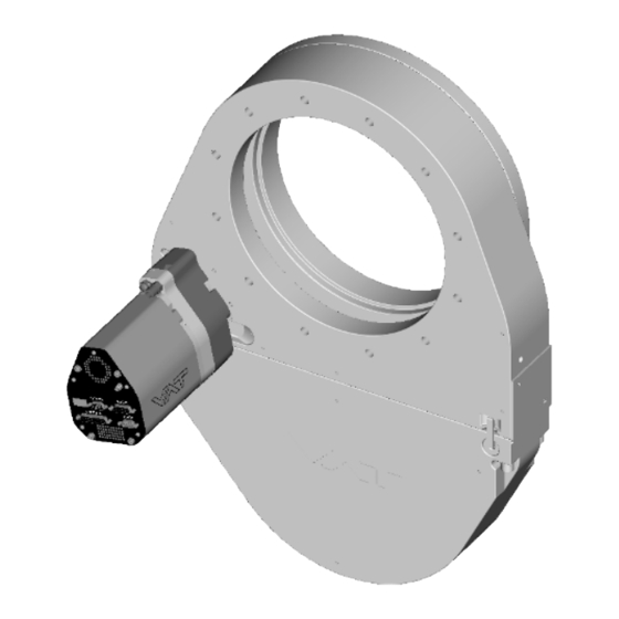
sample picture
Keep body parts and objects away from the valve
opening!
Hot surfaces; do not touch!
Loaded springs and/or air cushions are potential
hazards!
Wear gloves!
267736ED
2008-02-26
1/53
Advertisement
Table of Contents

Related Manuals for VAT Series 651

Summary of Contents for VAT Series 651
- Page 1 Installation, Operating & Maintenance Instructions Series 651 DN 320-400 (I.D. 12“ - 16”), Logic Pendulum control & isolation valve with extended control range with Logic interface This manual is valid for the valve ordering number(s): 651 . . - . . GC - ..
-
Page 2: Table Of Contents
Installation, Operating & Maintenance Instructions Series 651 DN 320-400 (I.D. 12“ - 16”), Logic Contents: 1 Use of product ................................3 Technical data ..............................3 2 Installation................................. 6 Unpacking................................ 6 Installation into the system ..........................6 Tightening torque ............................. 8 2.3.1... -
Page 3: Use Of Product
This product is a throttling pendulum valve with isolation functionality. It is intended to use for downstream pressure control applications. Use product for clean and dry indoor vacuum applications under the conditions indicated in chapter «Technical data» only! Other applications are only allowed with the written permission of VAT. Technical data Control and actuating unit Power input (α) - Page 4 Installation, Operating & Maintenance Instructions Series 651 DN 320-400 (I.D. 12“ - 16”), Logic Control and actuating unit (continuation) Sensor input Signal input 0-10 VDC / Ri>100 kΩ [connector: SENSOR] ADC resolution 0.23 mV Sampling time 10 ms ±24 VDC max.
- Page 5 Installation, Operating & Maintenance Instructions Series 651 DN 320-400 (I.D. 12“ - 16”), Logic Valve unit Pressure range at 20°C 1 x 10E-8 mbar to 1.2 bar (abs) - Aluminum (651 . . - . A . . - ..) - Aluminum hard anodized (651 .
-
Page 6: Installation
Installation, Operating & Maintenance Instructions Series 651 DN 320-400 (I.D. 12“ - 16”), Logic Installation Unpacking As this valve is a heavy component you should lift it with adequate equipment to prevent any injury to humans. Valves DN200 (8”) and larger are equipped with attachment points (tapped holes). Add eyebolts to these attachment points for lifting. - Page 7 This valve has a double sealed rotary feedthrough and optionally an intermediate pumping port for the actuator shaft. This port (1/8“ ISO/NPT) could be connected to the vacuum line, see Figure 2 below. This valve may optionally be equipped with a heating device. Connect VAT heating device according to manual of respective heating device.
-
Page 8: Tightening Torque
Installation, Operating & Maintenance Instructions Series 651 DN 320-400 (I.D. 12“ - 16”), Logic Tightening torque Tighten mounting screws of the flanges uniformly in crosswise order. Observe the maximum torque levels in the following table. Higher tightening torques deforms the valve body and may lead to malfunction of the valve. -
Page 9: Mounting With O-Ring In Grooves
Installation, Operating & Maintenance Instructions Series 651 DN 320-400 (I.D. 12“ - 16”), Logic 2.3.2 Mounting with O-ring in grooves ISO-F ASA-LP ISO-F ASA-LP Valve size max. tightening torque max. tightening torque (Nm) (lbs . ft) DN320 / 12“ 65-70... -
Page 10: Requirements To Sensor Connection
Installation, Operating & Maintenance Instructions Series 651 DN 320-400 (I.D. 12“ - 16”), Logic Requirements to sensor connection To achieve fast and accurate pressure control a fast sensor response is required. Sensor response time: < 50ms The sensor is normally connected to the chamber by a pipe. -
Page 11: Power And Sensor Connection (+24 Vdc Sensors)
Installation, Operating & Maintenance Instructions Series 651 DN 320-400 (I.D. 12“ - 16”), Logic 2.6.2 Power and sensor connection (+24 VDC sensors) [651 . . - . . G . - ../ 651 . . - . . H . - ..versions recommended]... -
Page 12: Power And Sensor Connection (±15 Vdc Sensors) Without Optional Sps Module
Installation, Operating & Maintenance Instructions Series 651 DN 320-400 (I.D. 12“ - 16”), Logic 2.6.3 Power and sensor connection (±15 VDC sensors) without optional SPS module [651 . . - . . G . - ../ 651 . . - . . H . - ..versions only]... -
Page 13: Power And Sensor Connection (±15 Vdc Sensors) With Optional Sps Module
Installation, Operating & Maintenance Instructions Series 651 DN 320-400 (I.D. 12“ - 16”), Logic 2.6.4 Power and sensor connection (±15 VDC sensors) with optional SPS module [651 . . - . . A . - ../ 651 . . - . . C . - ..versions only]... -
Page 14: Logic Interface Connection
The service port (connector: SERVICE) allows to connect the valve to a RS232 port of a computer. This requires a service cable and a software from VAT. You can either use our freeware 'Control View', which can be downloaded from or purchase our 'Control Performance Analyzer'. -
Page 15: Operation
Local operation means that the valve is operated via the service port using a computer or the Service Box 2. When using a computer, a service cable and a software from VAT are required. You can either download our freeware 'Control View' from or purchase our 'Control Performance Analyzer'. -
Page 16: Remote Operation
Installation, Operating & Maintenance Instructions Series 651 DN 320-400 (I.D. 12“ - 16”), Logic 3.1.2 Remote operation This product is equipped with a Logic interface to allow for remote operation. See section «Logic Interface» for details. ‘Control View’ software, 'Control Performance Analyzer' software or 'Service Box 2' may be used for monitoring during remote control. -
Page 17: Behavior In Case Of Power Failure
Display indicates F. position pendulum plate at the current position. *) Provided that battery pack of the VAT controller is charged. Charging time after power up is 2 minutes max.. All parameters are stored in a power fail save memory. Display information There is a 4 digit display located on the panel. - Page 18 Installation, Operating & Maintenance Instructions Series 651 DN 320-400 (I.D. 12“ - 16”), Logic Power up: Description Digit 1 Digit 2 Digit 3 Digit 4 At first all dots are illuminated then configuration is displayed: • Firmware version [e.g. 1E00]...
-
Page 19: Setup Procedure
Installation, Operating & Maintenance Instructions Series 651 DN 320-400 (I.D. 12“ - 16”), Logic Errors: Description Digit 1 Digit 2 Digit 3 Digit 4 Compressed air failure (< 4 bar / 55 psi) Compressed air on exhaust Fatal error occurred Error code. -
Page 20: Valve And Sensor Configuration
Installation, Operating & Maintenance Instructions Series 651 DN 320-400 (I.D. 12“ - 16”), Logic 3.6.2 Valve and sensor configuration Basic valve configuration must be adapted according to application needs. • Definition of valve plate position (CLOSE or OPEN) after power up sequence. Default is ‘close‘. -
Page 21: Learn
Installation, Operating & Maintenance Instructions Series 651 DN 320-400 (I.D. 12“ - 16”), Logic 3.6.4 LEARN LEARN adapts the PID controller of the valve to the vacuum system and its operating conditions. LEARN must be executed only once during system setup. - Page 22 Installation, Operating & Maintenance Instructions Series 651 DN 320-400 (I.D. 12“ - 16”), Logic Gasflow calculation for LEARN: Do not apply a different gasflow for learn than determined below. Otherwise pressure control performance may be insufficient. Note: Required pressure / flow regime must be known to calculate the most suitable learn gas flow for a specific application.
-
Page 23: Close Valve
Installation, Operating & Maintenance Instructions Series 651 DN 320-400 (I.D. 12“ - 16”), Logic Close valve Local operation: Remote operation: (‘Control View’, ‘Control Performance Analyzer’ or (Refer to chapter «Digital inputs» for details) ‘Service Box 2‘) Push CLOSE button Send CLOSE VALVE... -
Page 24: Operation With 2 Sensors
Installation, Operating & Maintenance Instructions Series 651 DN 320-400 (I.D. 12“ - 16”), Logic 3.10.1 Operation with 2 sensors [applicable with 651 . . - . . . E - ..version only] If 2 sensor operation is enabled, changeover between the sensors is done automatically during pressure control. For configuration refer to chapter «Setup procedure». -
Page 25: Tuning Of Control Performance
Installation, Operating & Maintenance Instructions Series 651 DN 320-400 (I.D. 12“ - 16”), Logic 3.10.2 Tuning of control performance Normally the default settings will result in good pressure control performance. For some applications tuning may be required to improve performance. - Page 26 Installation, Operating & Maintenance Instructions Series 651 DN 320-400 (I.D. 12“ - 16”), Logic 3.10.2.1 Gain factor adjustment The gain factor effects: • Stability • Response time Default value is 1. Adjustment range is from 0.0001 to 7.5. Higher gain results in:...
- Page 27 Installation, Operating & Maintenance Instructions Series 651 DN 320-400 (I.D. 12“ - 16”), Logic 3.10.2.3 Setpoint ramp adjustment Setpoint ramp effects: • Undershoot of pressure • Response time Default value for S is 1. Adjustment range for S is from 0 to 10 s.
-
Page 28: Logic Interface
Installation, Operating & Maintenance Instructions Series 651 DN 320-400 (I.D. 12“ - 16”), Logic 3.10.2.4 Valve speed adjustment Valve speed effects: • Response time Default value is 1000. Adjustment range is from 1 to 1000. This parameter effects valve plate actuating speed. -
Page 29: Functions And Wiring
Installation, Operating & Maintenance Instructions Series 651 DN 320-400 (I.D. 12“ - 16”), Logic 3.11.1 Functions and Wiring Logic interface allows for remote operation by means of digital and analog signals. Digital inputs may be operated either by switches or by voltage sources. - Page 30 Installation, Operating & Maintenance Instructions Series 651 DN 320-400 (I.D. 12“ - 16”), Logic b) Configuration with voltage source for digital inputs: Note: Use a shielded cable for analog inputs. Do not connect other pins than indicated above! Connector: Use only screws with 4-40UNC thread for fastening the DB-25 connector!
-
Page 31: Digital Inputs
Installation, Operating & Maintenance Instructions Series 651 DN 320-400 (I.D. 12“ - 16”), Logic 3.11.2 Digital inputs Function Signal type Description Priority This pin selects the control mode. This valve may either be operated as pressure controller or as position controller. - Page 32 Installation, Operating & Maintenance Instructions Series 651 DN 320-400 (I.D. 12“ - 16”), Logic Function Signal type Description Priority This function compensates the pressure gauge offset voltage and sets the pressure value to zero. In case of a 2 sensor system both sensor inputs will be adjusted.
-
Page 33: Digital Outputs
Installation, Operating & Maintenance Instructions Series 651 DN 320-400 (I.D. 12“ - 16”), Logic 3.11.3 Digital outputs Function Signal type Description This output is active in all operation modes and indicates either that the valve is open or that a service is requested. -
Page 34: Analog Inputs And Outputs
Installation, Operating & Maintenance Instructions Series 651 DN 320-400 (I.D. 12“ - 16”), Logic 3.11.4 Analog inputs and outputs Function Signal type Description The meaning of the setpoint input depends on the operation mode. LEARN: A voltage of 0-10V shall be applied to this input as pressure limit for learn. -
Page 35: Trouble Shooting
Installation, Operating & Maintenance Instructions Series 651 DN 320-400 (I.D. 12“ - 16”), Logic Trouble shooting Failure Check Action No dots lighted on display - 24 V power supply ok? - Connect valve to power supply according to «Electrical connection» and make sure that power supply is working. - Page 36 Installation, Operating & Maintenance Instructions Series 651 DN 320-400 (I.D. 12“ - 16”), Logic Failure Check Action Pressure reading is wrong - Sensor(s) connected? - Refer to «Electrical connection». - 2 sensor version present at - Check valve version on page 1. Verify configuration. Refer valve controller? to «Setup procedure».
-
Page 37: Maintenance & Repairs
Contamination from the process may influence the function and requires more frequent maintenance. Before carrying out any maintenance or repairs, please contact VAT. It has to be individually decided whether the maintenance/repair can be performed by the customer or has to be carried out by VAT. The fabrication number on the valve made in Switzerland Fabrication No.:... -
Page 38: Maintenance Procedures
Installation, Operating & Maintenance Instructions Series 651 DN 320-400 (I.D. 12“ - 16”), Logic Maintenance procedures Keep fingers out of the valve during maintenance work. Use cleanroom gloves during maintenance work. Two preventive maintenance procedures are defined for this valve. These are: •... - Page 39 Installation, Operating & Maintenance Instructions Series 651 DN 320-400 (I.D. 12“ - 16”), Logic Note: Electrical power and compressed air is required to perform steps 2 to 9 during disassembly respectively 9 to 2 during assembly. D e s c r i p t i o n Required tool Vent both valve chambers.
- Page 40 Installation, Operating & Maintenance Instructions Series 651 DN 320-400 (I.D. 12“ - 16”), Logic D e s c r i p t i o n Required tool 10. Remove gate and body o-ring from sealing ring carefully with a soft tool.
- Page 41 Installation, Operating & Maintenance Instructions Series 651 DN 320-400 (I.D. 12“ - 16”), Logic D e s c r i p t i o n Required tool • CV software 19. Release the valve from safety mode. Refer to «Safety mode» for details 20.
- Page 42 Installation, Operating & Maintenance Instructions Series 651 DN 320-400 (I.D. 12“ - 16”), Logic D e s c r i p t i o n Required tool • Soft tool (o-ring remover) 25. Remove actuator shaft seals carefully with a soft tool.
- Page 43 Installation, Operating & Maintenance Instructions Series 651 DN 320-400 (I.D. 12“ - 16”), Logic D e s c r i p t i o n Required tool 36. Turn on power of controller. Note: valve moves to close position. open end wrench 37.
-
Page 44: Option Board
Installation, Operating & Maintenance Instructions Series 651 DN 320-400 (I.D. 12“ - 16”), Logic Option board The option board may or may not be equipped in your valve depending on the order. Refer to page 1 of this manual to check valve version. -
Page 45: Retrofit / Replacement Procedure
Installation, Operating & Maintenance Instructions Series 651 DN 320-400 (I.D. 12“ - 16”), Logic 5.2.2 Retrofit / replacement procedure ESD Precaution! All work on the control and actuating unit has to be done under ESD protected environment to prevent electronic components from damage! - Page 46 Installation, Operating & Maintenance Instructions Series 651 DN 320-400 (I.D. 12“ - 16”), Logic Description Required tool Remove female screw locks from POWER, Open end wrench 4.5 mm SENSOR and INTERFACE connectors. Pozidriv screw driver Remove the panel screws. size 1 Lift the panel carefully.
- Page 47 Installation, Operating & Maintenance Instructions Series 651 DN 320-400 (I.D. 12“ - 16”), Logic Description Required tool Remove or replace interface board. Remove or replace master board. Remove or replace option board. Insert master board and interface board in reverse order as disassembled at correct positions (seesteps 6 to 5).
-
Page 48: Drawing
Installation, Operating & Maintenance Instructions Series 651 DN 320-400 (I.D. 12“ - 16”), Logic Drawing VAT Vakuumventile AG, CH-9469 Haag, Switzerland 267736ED 48/53 Tel +41 81 771 61 61 Fax +41 81 771 48 30 CH@vatvalve.com www.vatvalve.com 2008-02-26... -
Page 49: Spare Parts
Installation, Operating & Maintenance Instructions Series 651 DN 320-400 (I.D. 12“ - 16”), Logic Spare parts Please specify the fabrication number of the valve (see yellow label on valve) when ordering spare parts. This is to ensure that the appropriate spare parts are supplied. -
Page 50: Valve Unit
322355 Actuator B2 *) 346966 Note: Use only spare parts manufactured by VAT to assure safe and reliable operation! *) Refer to figures on next page to check for actuator position options. VAT Vakuumventile AG, CH-9469 Haag, Switzerland 267736ED 50/53 Tel +41 81 771 61 61 Fax +41 81 771 48 30 CH@vatvalve.com www.vatvalve.com... -
Page 51: Accessories
Installation, Operating & Maintenance Instructions Series 651 DN 320-400 (I.D. 12“ - 16”), Logic Actuator position options: Valve with B1 actuator (standard) Valve with B2 actuator (option) Accessories Item Description Part number 24 VDC power supply unit 249775 (input: 100 – 240 VAC) ‘Control Performance Analyzer’... -
Page 52: Centering Ring With Viton O-Ring
Installation, Operating & Maintenance Instructions Series 651 DN 320-400 (I.D. 12“ - 16”), Logic 7.3.1 Centering ring with Viton o-ring Description Valve size DN 320 / 12” DN 350 / 14” DN 400 / 16” Product ordering number 65150 - .. -
Page 53: Warranty
(including any delay in or failure to deliver), packaging, storage or use of any product sold or delivered by VAT shall fail to conform to the...
Need help?
Do you have a question about the Series 651 and is the answer not in the manual?
Questions and answers