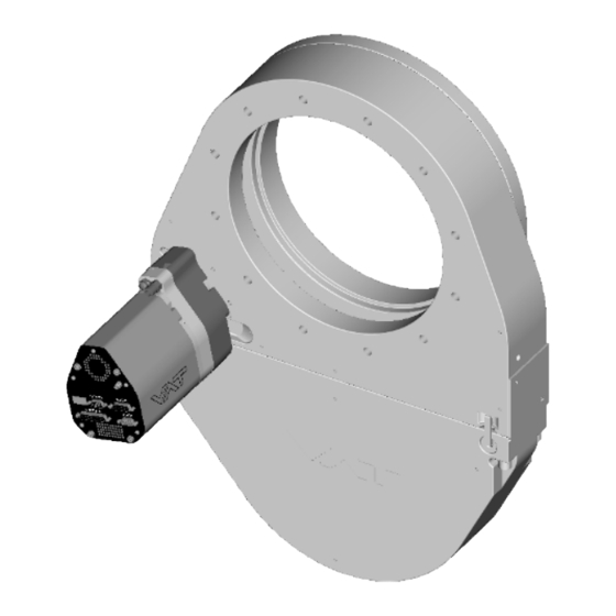
Sign In
Upload
Manuals
Brands
VAT Manuals
Control Systems
Series 651
VAT Series 651 Manuals
Manuals and User Guides for VAT Series 651. We have
2
VAT Series 651 manuals available for free PDF download: Installation, Operating, & Maintenance Instructions
VAT Series 651 Installation, Operating, & Maintenance Instructions (99 pages)
Brand:
VAT
| Category:
Control Unit
| Size: 4.75 MB
Table of Contents
Table of Contents
3
Description of Product
5
Identification of Product
5
Use of Product
5
Used Abbreviations
5
Related Documents
5
Important Information
5
Technical Data
6
Control and Actuating Unit
6
Valve Unit
8
Safety
10
Compulsory Reading Material
10
Danger Levels
10
Personnel Qualifications
11
Safety Labels
11
Design and Function
12
Design
12
Function
13
Pressure Control System Overview and Function
14
Principle of a Pressure Control System
15
Installation
16
Unpacking
16
Installation into the System
17
Installation Space Condition
18
Connection Overview
19
Installation Procedure
19
Tightening Torque
21
Mounting with Centering Rings
21
Mounting with O-Ring in Grooves
22
Admissible Forces
22
Requirements to Sensor Connection
23
Electrical Connection
23
Ground Connection
24
Sensor Supply Concepts
25
Power and Sensor Connection (+24 VDC Sensors)
26
Power and Sensor Connection (±15 VDC Sensors) Without Opt. SPS Module
28
Power and Sensor Connection (±15 VDC Sensors) with Optional SPS Module
30
Service Port Connection
31
Functions and Wiring
32
Digital Inputs
34
Digital Outputs
36
Analog Inputs and Outputs
37
Initial Operation
38
Setup Procedure
38
Logic Interface Configuration
38
Valve Configuration
39
Sensor Configuration
40
Zero
40
LEARN (Adaptive)
41
Pressure Control Configuration
43
Pressure Control Algorithem
46
Tuning of Control Performance
50
Tuning of Pressure Control (Adaptive)
51
Tuning of Pressure Control Performance with Fixed PI Control
56
Tuning of Pressure Control with Soft Pump
59
Operation
62
Normal Operation
62
Local Operation
63
Remote Operation
64
Close Valve
65
Open Valve
65
Position Control
65
Pressure Control
65
Operation with 2 Sensors
66
Display Information
67
Power up
67
Operation
68
Errors
68
Safety Mode
68
Service Indication
69
Operation During Power up
69
Behavior in Case of Power Failure
69
Operation under Increased Temperature
70
Behavior in Case of Compressed Air Pressure Drop
70
Trouble Shooting
71
Maintenance
73
Maintenance Intervals
73
Maintenance Procedures
74
Replacement of Isolation Seals and Cleaning
75
Replacement of Actuator Shaft Seals
78
Replacement of Option Board
83
Retrofit / Replacement Procedure
85
Repairs
88
Dismounting and Storage
89
Dismounting
89
Storage
90
Packaging and Transport
91
Packaging
91
Transport
92
Disposal
93
Spare Parts
94
Drawing
94
12.1.1 Valve Unit with Seals and Grease
95
Control and Actuating Unit
96
Accessories
97
Appendix
98
Advertisement
VAT Series 651 Installation, Operating, & Maintenance Instructions (53 pages)
Pendulum control & isolation valve
Brand:
VAT
| Category:
Control Systems
| Size: 2.41 MB
Table of Contents
Table of Contents
2
1 Use of Product
3
Technical Data
3
2 Installation
6
Unpacking
6
Installation into the System
6
Tightening Torque
8
Mounting with Centering Rings
8
Mounting with O-Ring in Grooves
9
Admissible Forces
9
Requirements to Sensor Connection
10
Electrical Connection
10
Sensor Supply Concepts
10
Power and Sensor Connection (+24 VDC Sensors)
11
Power and Sensor Connection (±15 VDC Sensors) Without Optional SPS Module
12
Power and Sensor Connection (±15 VDC Sensors) with Optional SPS Module
13
Logic Interface Connection
14
Service Port Connection
14
3 Operation
15
Introduction
15
Local Operation
15
Remote Operation
16
Safety Mode
16
Operation under Increased Temperature
16
Behavior During Power up
16
Behavior in Case of Power Failure
17
Display Information
17
Setup Procedure
19
Interface Configuration
19
Valve and Sensor Configuration
20
Zero
20
Learn
21
Close Valve
23
Open Valve
23
Position Control
23
Pressure Control
23
Operation with 2 Sensors
24
Tuning of Control Performance
25
Logic Interface
28
Functions and Wiring
29
Digital Inputs
31
Digital Outputs
33
Analog Inputs and Outputs
34
4 Trouble Shooting
35
5 Maintenance & Repairs
37
Maintenance Procedures
38
Option Board
44
Durability of Power Fail Battery
44
Retrofit / Replacement Procedure
45
6 Drawing
48
7 Spare Parts
49
Control Unit
49
Valve Unit
50
Accessories
51
Centering Ring with Viton O-Ring
52
8 Warranty
53
Advertisement
Related Products
VAT 651 GC Series
VAT 651 GE Series
VAT 651 AC Series
VAT 651 AE Series
VAT 651 HC Series
VAT 651 HE Series
VAT 651 CC Series
VAT 651 CE Series
VAT 650 WL Series
VAT 653-GH Series
VAT Categories
Control Unit
Controller
Refrigerator
Keypad
Control Systems
More VAT Manuals
Login
Sign In
OR
Sign in with Facebook
Sign in with Google
Upload manual
Upload from disk
Upload from URL