Table of Contents

Subscribe to Our Youtube Channel
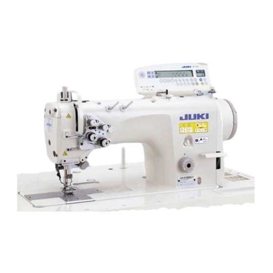
Related Manuals for JUKI LH-4128-7


Summary of Contents for JUKI LH-4128-7
- Page 1 ® Direct-drive, High Speed, 2-Needle, Needle-feed, Lockstitch Machine LH-4128 Direct-drive, High Speed, 2-Needle, Needle-feed, Lockstitch Machine with Automatic Thread Trimmer LH-4128-7/4168-7/4188-7 ENGINEER’S MANUAL 40038257 No.E367-03...
- Page 2 PREFACE This Engineer’s Manual is written for the technical personnel who are responsible for the service and maintenance of the machine. The Instruction Manual for these machines intended for the maintenance personnel and operators at an apparel factory contains operating instructions in detail. And this manual describes “Standard Adjustment”, “Adjustment Procedures”, “Results of Improper Adjustment”, and other important information which are not covered by the Instruction Manual.
-
Page 3: Table Of Contents
2. Name of each component ................2 3. Model numbering sysytem ................3 (1) LH-4128 (without a thread trimmer) ................3 (2) LH-4128-7•LH-4168-7•LH-4188-7 (with a thread trimmer) ........4 4. Special notes for safe operation ..............5 5. Standard adjustment ..................8 (1) Needle bar and feed dog .................... - Page 4 11.Sewing specification .................. 66 12.List of gauge components ................ 67 (1) LH-4128 ........................67 (2) LH-4128F ........................69 (3) LH-4128-7 ........................70 (4) LH-4168-7 ........................71 (5) LH-4188-7 ........................72 13. List of the major components ..............73 (1) List of expendable parts ..................73 (2) Other renewal parts ....................
-
Page 5: Specifications
(3.2 to 25.4mm) Lift of presser foot 12mm by knee lifter, 5.5mm by hand lifter lever, 9mm by knee lifter with wiper Lubricating oil JUKI NEW Defrix oil No. 1 (equivalent ISO VG7) JUKI grease A (Part No. : 40006323) Grease JUKI grease A (Part No. -
Page 6: Name Of Each Component
2. Name of each component Separately driven needle Pedal Bobbin winder changeover switch Knee patch Thread stand (LH-4168-7, LH-4188-7 only) Power switch Oil supply opening Thread take-up cover Hand switch Reverse feed control lever Finger guard Operation panel Hand lifter lever Thread tension controller Control box –... -
Page 7: Model Numbering Sysytem
3. Model numbering system (1) LH-4128 (without a thread trimmer) L H 4 1 2 8 A 0 B — A A Classification for the head specifications 11 to 12 Classification for wiper and auto-reverse feed Semi-dry head Without wiper, with auto-reverse feed Classification for attachment application Classification for the head specifications Standard throat plate, standard face plate,... -
Page 8: Lh-4128-7•Lh-4168-7•Lh-4188-7(With A Thread Trimmer)
(2) LH-4128-7•LH-4168-7•LH-4188-7(with a thread trimmer) L H 4 1 F A 7 W B — A A 5 to 6 Classification for the model 2-needle lock stitch needle feed 2-needle lock stitch needle feed with rectan- gular stitching function Shuttle spec. for 2-needle lock stitch needle... -
Page 9: Special Notes For Safe Operation
(2) The machine oil (JUKI New Deflex Oil No.1) shall be supplemented so that the level gauge remains in the range between the upper and lower engraved marker lines of the oil tank. - Page 10 (5) How to pass the bobbin thread (The bobbin thread winding direction is indicated by the arrow.) o LH-4128 Latch hook o LH-4168-7 Hook with a thread trimmer and an separately o LH-4128-7 Latch hook with a thread trimmer driven needle o LH-4188-7 Hook with a thread trimmer and an separately driven needle (6) When synthetic threads are used, the thread guide arm (asm.) for the thread stand (asm.) if the thread flaps...
- Page 11 MEMO – 7 –...
-
Page 12: Standard Adjustment
(1) Needle bar and feed dog Standard Adjustment 1) Initial position of the needle bar Conditions o The needle bar is in the lowest dead point. o Feed amount : Minimum o LH-4128, LH-4128-7 o LH-4168-7, LH-4188-7 ± 13.5 ± 14.1 0.1mm... - Page 13 Adjustment Procedure Results of Improper Adjustment W h e n t h e s t i t c h l e n g t h i s 1) Initial position of the needle bar maximized, the feed dog will 1. Set the stitch dial at “Minimum” on the scale. come in contact with the throat plate 2.
-
Page 14: Adjustment Of The Right And Left Feed Dog Positions, Height, And Gradient
Standard Adjustment 2) Adjustment of the right and left feed dog positions, height, and gradient Conditions o Feed amount : Minimum is in the hightest position of its stroke, it should rise 1 ± 0.1mm from the top surface o When the feed dog of the throat plate Top surface of the throat plate Feed base... - Page 15 . Turn the roulette section to adjust the gradient. Standard adjustment o LH-4128, LH-4128-7, LH-4168-7 Position where the engraved marking dot of the feed base arm coincides with the engraved marking dot of the feed base arm shaft .
-
Page 16: Needle Bar Height
3) Needle bar height Conditions o Needle bar should be in its lowest dead point. o Feed amount : Minimum o LH-4128 o LH-4128-7 Meets with the upper engraved marker line Maker lines engraved on the needle bar Needle bar... - Page 17 Adjustment Procedure o Change in height of the needle 3) Needle bar height bar may result in stitch skipping o LH-4128, LH-4128-7 or thread breakage. 1. Set stitch dial “Minimum”. 2. Turn the handwheel to bring needle bar to the lowest dead point.
-
Page 18: Needle Clamp
Needle bar should be in the lowest dead point. o LH-4128 o LH-4168-7 o Feed amount : Minimum o LH-4128-7 o LH-4188-7 o The needle should enter of the needle slot in the feed dog. Needle slot in the feed dog Feed bar –... - Page 19 Stitch skipping and thread 5) Needle entry breakage will be caused. o LH-4128, LH-4128-7 o Poorly tensed seam will result. 1. Minimize the feed amount by rotating the feed adjusting dial. o W h e n t h e f e e d d o g h a s 2.
-
Page 20: Timing Between The Needle And The Hook
: 2.5mm (For G type, it should be set at 3.5mm) (For F type, it should be set at 2mm) o LH-4128 o LH-4168-7 LH-4128-7 LH-4188-7 0 to 0.05mm Lift of the needle bar when the lower maker line on the needle bar meets the bottom and of the needle bar frame : A=2.2mm... - Page 21 Adjustment Procedure Results of Improper Adjustment List of the needle bar o S t i t c h s k i p p i n g o r t h r e a d Clearance between the needle and the blade point of the hook breakage will result.
-
Page 22: Initial Position Of The Bobbin Case Opening Lever
(3) Initial position of the bobbin case opening lever Standard Adjustment o LH-4128, 4128-7, 4168-7 When adjustment is based on the central point (green engraved marker line) of the 3-serial engraved marking, the amount of opening for the inner hook stop and the throat plate rib becomes 0.3mm (standard adjusting value). - Page 23 Adjustment Procedure Results of Improper Adjustment When it stays on the side of the o LH-4128, 4128-7, 4168-7 shorter engraved marking 1. Adjust the hand wheel to the central point of the green engraved o Towel-face stitches, loosened marker line of the 3-serial engraved marking, and press the inner hook stitches or thread breakage will claw in the direction of the arrow.
-
Page 24: Clearance Between The Throat Plate And The Bobbin Case Stopper
Size A (mm) of a clearance between the upper plane of the throat plate hook stop section groove and the upper plane of the inner hook stop section Model Dimension A (mm) LH-4128 0.8±0.1mm LH-4128-7 LH-4168-7 0.9±0.1mm LH-4188-7 1.0±0.1mm Part No. Name of part... - Page 25 Adjustment Procedure Results of Improper Adjustment 1. Remove the throat plate bobbin case opening lever, feed dog and If the clearance provided between needle. the throat plate and the bobbin case 2. Loosen three screws which are used to secure the hook driving shaft stopper is larger than the specified gear.
-
Page 26: Relation Between The Main Shaft And The Lower Shaft
(6) Relation between the main shaft and the lower shaft Standard Adjustment Worker side LH-4188-7 only Lower dead point of the ° needle bar (180 Make a reverse rotation by 13.6mm. ° (167.5 LH-4128 (-7) LH-4168-7 Condition that the sewing machine is laid down. - Page 27 Adjustment Procedure Results of Improper Adjustment 1. Turn the hand wheel until it reaches the lower dead point of the If the timing between the main shaft needle bar. and lower shaft does not match, 2. Confirm that the engraved marker line of the sprocket is in parallel thread trimming timing, needle to the upper plane...
-
Page 28: Lubrication
(7) Lubrication Standard Adjustment 1) Lubrication system 2) How to clean the filter section Plunger Oil tank Circulation tube Bottom cover Upper engraved maker line Lower engraved maker line 3) Hook oil amount Condition: After 30 seconds of idling, there shall be generation of oil splashes in 5 seconds. - Page 29 (Asm.). 1. Remove oil hole cap and fill the oil tank with JUKI New Defrix Oil No. 1 using the oiler supplied with the machine. 2. Feed the lubricant so that the tip of the oil amount indicating rod...
-
Page 30: Oil In The Feed Box
Standard Adjustment 4) Oil in the feed box 5) Replacement of the hook shaft oil wick – 26 –... - Page 31 2. The amount of oil in the feed box is 60 to 65ml. (The oil type shall be the bed. JUKI Machine Oil No. 18 or JUKI New Defrix Oil No. 2.) 3. The oil in the feed box is different from the hook oil. Do not replenish the oil.
-
Page 32: Replenishing Grease To The Specified Places (For Lh-4168-7, Lh-4188-7 Only)
Standard Adjustment 6) Replenishing grease to the specified places (for LH-4168-7, LH-4188-7 only) 1. Replenishing grease to the needle bar drive cam section – 28 –... - Page 33 Otherwise, error No.E220 or error No.E221 is displayed again. 2. For replenishing grease to the specified places below, use JUKI GREASE A TUBE (Part No. 40006323) or JUKI GREASE B TUBE (Part No. 40013640), supplied as ac- cessories. If grease other than the specified one is used, breakage of components will be caused.
- Page 34 Standard Adjustment 2. Center link section – 30 –...
- Page 35 2. Center link section 1) Remove the rubber cap locates at the top surface of face section and the face plate. 2) Fill joint supplied as accessories with JUKI grease B from the JUKI grease B tube. 3) Connect pipe with nipple, right...
-
Page 36: Forward And Reverse Stitch Pitches
(8) Forward and reverse stitch pitches Standard Adjustment Conditions o When the stitch dial is set at “3”, the difference in the stitch length between the normal feed stitching and reverse feed stitching should be 0.2mm or less. Feed regulator base Feed regulator base Notch Feed regulator base rod... - Page 37 Adjustment Procedure Results of Improper Adjustment 1. Set the stitch dial at “3”. o The stitch length for reverse feed 2. Loosen two screws in the feed regulator base. stitching will be different from that 3. Move feed regulator to base pin in the direction of the arrow to for the normal feed stitching.
-
Page 38: Adjusting The Needle Stop Position
(9) Adjusting the needle stop position Standard Adjustment 1) Needle-up stop position of the sewing machine Red maker dot 2) Needle-down stop position of the sewing machine Upper surface of the feed dog 0 to 3mm – 34 –... - Page 39 Adjustment Procedure Results of Improper Adjustment Stop position after thread trimming (1) The standard needle stop position is obtained by aligning marker dot on the pulley cover with white marker dot on the handwheel. (2) Stop the needle in UP position, turn OFF the power, and loosen screw to perform adjustment within the slot of the screw.
-
Page 40: Disc Release Changeover For Lap Lifter
(10) Disc release changeover for lap lifter Standard Adjustment Presser lifting plate (There is a hexagon socket head cap screw behind the rubber cap that has been removed.) – 36 –... - Page 41 Adjustment Procedure Results of Improper Adjustment o LH-4128-7, 4168-7, 4188-7 The lap lifter and the thread tension release are not interactive at the time of shipment. When loosening the thread, press the disc releasing plate to lift the disc. 1. When interlocking the thread tension release (1) Remove the rubber cap.
-
Page 42: Needle Bar Stroke Adjustment (For Lh-4168-7, Lh-4188-7 Only)
(11) Needle bar stroke adjustment (for LH-4168-7, LH-4188-7 only) Standard Adjustment Model Dimension A (mm) LH-4168-7 31.6±0.2mm LH-4188-7 32.6±0.2mm Stroke small Stroke large Needle drive Needle stop – 38 –... - Page 43 Adjustment Procedure Results of Improper Adjustment 1. Remove the three screws , and remove the top cover 2. Remove the eight screws , and remove the changeover solenoid 3. Adjust the needle bar stroke by adjusting the amount of screw-in of the needle drive stopper .
-
Page 44: Thread Trimming Device
(12) Thread trimming device Standard Adjustment 1) Moving knife position 2) Adjusting the height of the counter knife – 40 –... - Page 45 Adjustment Procedure Results of Improper Adjustment Moving knife position o Any deviation from this adjusting 1. Loosen and adjust the connector screw on the rear side of the bed value can cause failure in thread so that Distance between tip of the standby moving knife and that trimming due to poor thread of the counter knife...
-
Page 46: Adjusting The Thread Presser Spring
Standard Adjustment 3) Adjusting the thread presser spring – 42 –... - Page 47 Adjustment Procedure Results of Improper Adjustment 3) Adjusting the thread presser spring 1. Insert a rod (thin rod, wrench, etc.) into adjusting hole in thread presser spring base , and loosen setscrew with a hexagonal wrench key of 1.5 mm. 2.
-
Page 48: Position Of The Thread Trimming Cam And The Thread Trimming Timing
Standard Adjustment 4) Position of the thread trimming cam and the thread trimming timing B side 5) Clearance between the thread trimming cam and the thread loosening arm Enlarged Part A in the top right diagram B side – 44 –... - Page 49 Adjustment Procedure Results of Improper Adjustment 4) Position of the thread trimming cam and the thread trimming timing 1. Let the arm's engraved marker dot coincide with the engraved marker dot (red) of the hand wheel 2. In the state that the knife driving arm is keeping contact with the stopper of the thread trimmer driving arm, push in the cam roller...
-
Page 50: Adjustment Of Thread Tension Release
Standard Adjustment 6) Adjustment of thread tension release Clearance 0 – 46 –... - Page 51 Adjustment Procedure Results of Improper Adjustment 6) Adjustment of thread tension release 1. Confirm that there is no play between the disc rise pin and the disc rise plate 2. If presence of some play is perceived, loosen the nut and shift the wire to the left side so that the clearance can be adjusted to zero...
-
Page 52: Wiper Components
(13) Wiper components Standard Adjustment ± 0.2mm Wiper length Wiper 2 to length Wiper position Wiper position (14) Reverse solenoid position Standard Adjustment Conditions o Stitch length (feed amount): Maximum o A clearance of 0.5 to 1mm should be provided between the reverse feed solenoid and the plunger rubber washer when the reverse feed control lever... - Page 53 Adjustment Procedure Results of Improper Adjustment 1. Loosen the screw and then tighten it in the position where a o If the wiper is too long the clearance of 1.1±0.2mm is secured between the wiper base wiper will interface with the the presser bar metal needle clamp while the sewing 2.
-
Page 54: Initial Position Of The Reverse Feed Control Lever
(15) Initial position of the reverse feed control lever Standard Adjustment 1) Auto-back Conditions o Stitch length (feed amount) should be maxi- Lightly press the mized. reverse feed control lever o Lightly press the reverse feed control le- until the lever is aligned with the , a clearance of 0.5 ±... - Page 55 Adjustment Procedure Results of Improper Adjustment 1) Auto-back If the clearance provided between 1. Set the stitch dial at the maximum value on the scale. the back lever stopper and the re- 2. Lightly press reverse feed control lever down until it meets reverse verse feed control lever is 0 (zero): .
-
Page 56: Assembling/Adjusting The Knee-Lifter Detecting Device
(16) Assembling/adjusting the knee-lifter detecting device Standard Adjustment 1) Assembling the knee-lifter detection sensor plate (asm.) (Caution) To use the knee-lifter, be sure to set the function to lift the presser foot after thread trimming Viewed from A (function setting No.055 of the control box) inoperative (“0”: off). - Page 57 Adjustment Procedure Results of Improper Adjustment 1) Assembling the knee-lifter detection sensor plate (asm.) o If the clearance is larger than the 1. Remove the knee-lifter plate vertical shaft installing arm and the specified value, detection failure two setscrews that are temporarily fixed on the bottom cover. may result.
-
Page 58: Connecting The Cords
Standard Adjustment 3) Connecting the cords 4) Adjusting the knee-lifter detection seat (asm.) Condition: The LED starts to light up when the presser foot goes up by 5 mm Detecting section Align end surfaces Magnet LED * The knee-patch plate and other parts are excluded from the above illustration. - Page 59 Adjustment Procedure Results of Improper Adjustment 3) Connecting the cords o If the ground cord (asm.) 1. Remove screw locating at the left-hand side of the power switch. not connected, maloperation Place the top end of ground cord (asm.) corning from knee-lifter may be caused.
-
Page 60: Separately Driven Needle Changeover Switch (For Lh-4168-7, Lh-4188-7 Only)
6. Separately driven needle changeover switch (for LH-4168-7, LH-4188-7 only) : Left-hand needle changeover switch When this switch is pressed, left-hand needle goes up. When it is presser again, the needle comes down. : Right-hand needle changeover switch When this switch is pressed, right-hand needle goes up. -
Page 61: Gauge Replacing Procedure
7. Gauge replacing procedure (1) How to remove the gauge 1) Turn OFF the power switch. 2) Remove the slide plate, needle, needle clamp, presser foot, throat plate and feed dog. * In the case of a thread trimming machine provided with a wiper, refer to the table of “5.-(13) Wiper components”. - Page 62 Raise the sewing machine. Attach the throat plate in position. 10) Attach the presser foot in position. 11) Attach the wiper in position in the case of the thread trimmer. Refer to “5.-(13) Wiper components” 12) Adjust the feed dog support screw Loosen the nut , adjust the feed dog support screw to the position where it comes in contact with...
-
Page 63: Needle Feed/Bottom Feed Changeover
8. Needle feed/bottom feed changeover [Bottom feed changeover] 1. Adjust the feed control dial to the minimum position and loosen the nut of the needle bar rocking rod . Move the needle bar rocking rod from the needle bar rocking rod arm to the needle throwing rod fixing base and fix it with the nut... - Page 64 [Changeover to Needle Feed] Procedures below are the reverse steps for changeover to needle feed. 1. Loosen nut and move needle bar rocking rod from needle throwing rod fixing base to needle bar rocking rod arm . Fix it temporarily with nut .
- Page 65 MEMO – 61 –...
-
Page 66: Replacing The Timing Belt
9. Replacing the timing belt Belt tension gauge Belt tension gauge S No11 T E N S I O N M 0 0 4 . 0 g / m 8 5 . 1 W 0 1 5 . 0 m m / R S 0 2 2 4 Feed control base (butterfly type) - Page 67 (1) How to remove the timing belt 1) Remove the window plate, two screws , and idler 2) Remove the hand wheel and pulley cover 3) Loosen the setscrew of the coupling . (The first screw is fastened flat.) 4) Turn the four screws and remove the motor 5) Tilt the sewing machine and remove the oil tank For disassembly procedures, remove the four pipe stops...
-
Page 68: Installation/Removal Of The Needle Bar Rocking Base
10. Installation/removal of the needle bar rocking base – 64 –... - Page 69 (1) Removal of the needle bar rocking base 1. Remove top cover (3 screws), stop plug (2 screws), face plate (3 screws), thread take-up lever guard (2 screws), presser stroke adjusting screw , cap , and rocking base thrust holder (2 screws).
-
Page 70: Sewing Specification
11. Sewing specification Refer to the table below when the sewing specification is changed from the standard. Table of sewing specifications Name of part S type G type F type Thread tension spring Part No. Part No. Part No. 22921704 22962005 D3129555D00 Wire diameter... -
Page 71: List Of Gauge Components
12. List of gauge components (1) LH-4128 (1/2) Throat plate Needle gauge size Throat plate (Lower feed) Feed dog (Throat feed) Code ø1.7 ø1.9 (Option) 2.2mm inch Part No. Part No. Part No. Part No. Part No. Part No. 40033563 22625107 22845200 —... - Page 72 (1) LH-4128 (2/2) Needle gauge size Needle clamp asm. Presser foot asm. (Tip-divided) (Tip-divided) (Lower feed) Code (Wire Type) (Hole Type) inch . Part No. Part No. Part No. Part No. Part No. 40035896 40026027 10147650 40035896 10391852 (Clearance 2.0mm) 5/32 40026029 10147759...
-
Page 73: Lh-4128F
(2) LH-4128F Throat plate Swivel guide Needle gauge size Throat plate Feed dog Presser foot asm. for Taping Presser asm. 1.15 ø1.4 ø1.4 Code (Option) inch Part No. Part No. Part No. Part No. Part No. Part No. 22625107 22628002 40033563 40035883 22627152... -
Page 74: Lh-4128-7
(3) LH-4128-7 Needle gauge size Throat plate Feed dog Presser foot asm. (Tip-divided) (Tip-divided) ø1.9 ø1.7 3.2mm Code (Option) inch Part No. Part No. Part No. Part No. . Part No. Part No. 40035896 40035881 40061270 40035890 40053705 40035896 (Clearance 2.0mm) -
Page 75: Lh-4168-7
(4) LH-4168-7 Needle gauge size Throat plate Feed dog Presser foot asm. (Tip-divided) (Tip-divided) 3.2mm ø1.7 ø1.9 Code (Option) inch Part No. Part No. Part No. Part No. Part No. Part No. 40035896 40035881 40061270 40035890 40053705 40035896 (Clearance 2.0mm) 5/32 40025485 40061271... -
Page 76: Lh-4188-7
(5) LH-4188-7 Needle gauge size Throat plate Feed dog Presser foot asm. ø2.4 (Tip-divided) (Tip-divided) ø1.9 3.2mm Code inch Part No. Part No. Part No. Part No. Part No. 40035896 40035881 40061270 40053705 40035896 (Clearance 2.0mm) 5/32 40025485 40061271 40071911 40035897 40071909 3/16... -
Page 77: List Of The Major Components
Idline revention sheet LH-4188-7 B1425526000 Needle clamp setscrew LH-4168-7, LH-4188-7 Hexagon socket SM6030672TP Feed dog setscrew LH-4128, LH-4128-7, LH-4168-7, LH-4188-7 head cap screw M3 L=6 1) Needle entry spacer Thickness: ±0.02mm Part No. Part name 40055495 Needle entry spacer A0 2.8mm... - Page 86 MEMO – 82 –...
-
Page 87: Drawing Of The Table
2 x ø3.5 depth 10 3 x ø13 through hole 2 x ø3.5 depth 10 2-ø3.4 on the bottom surface, depth 10 JUKI rogo type X–X X–X (2 pcs.) T–T Z–Z (2 pcs.) Y–Y (2 pcs.) C1.5 to C2.5 (For hinge side only) V–V (1:1) (3 pcs.) - Page 88 MEMO...
- Page 89 ISO14001 : 2004 REG.NO.JSAE389 CM001 Juki Corporation operates an environmental management system to promote and conduct the following as the company engages in the research, development, design, sales, distribution,and maintenance of industrial sewing machines, household sewing machines, industrial robots, etc., and in the provision of sales and maintenance services...
Need help?
Do you have a question about the LH-4128-7 and is the answer not in the manual?
Questions and answers