Table of Contents
Advertisement
Available languages
Available languages
Quick Links
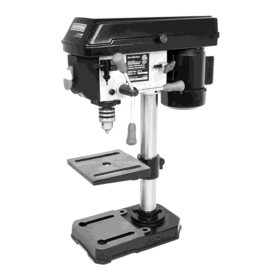
Operator's Manual
8-in. DRILL PRESS
1/3 HP MOTOR
Model 124.47747
CAUTION: Before using this
product, read this manual and
follow all its Safety Rules
and Operating Instructions.
Sears Brands Management Corporation,
Hoffman Estates, IL 60179 U.S.A
Safety Instructions
Assembly
Operation
Maintenance
Troubleshooting
Parts List
Español
21
Advertisement
Chapters
Table of Contents

Subscribe to Our Youtube Channel
Related Manuals for Craftsman 124.47747


Summary of Contents for Craftsman 124.47747
- Page 1 Operator’s Manual 8-in. DRILL PRESS 1/3 HP MOTOR Model 124.47747 Safety Instructions CAUTION: Before using this Assembly product, read this manual and follow all its Safety Rules Operation and Operating Instructions. Maintenance Troubleshooting Parts List Español Sears Brands Management Corporation,...
-
Page 2: Table Of Contents
TABLE OF CONTENTS Specifications........................2 Safety Instructions ......................3 - 6 Getting To Know Your Machine ....................7 Contents of Package .....................7 - 8 Installation ........................8 Assembly ........................9 - 10 Adjustments.......................11 - 12 Operation........................13 - 14 Maintenance ........................15 Electricals & Wiring Diagram ..................5 & 15 Troubleshooting ......................16 Notes ........................17 Parts Diagram &... -
Page 3: Safety Instructions
SAFETY INSTRUCTIONS IMPORTANT! Safety is the single most important consideration in the operation of this equipment. The following instructions must be followed at all times. Failure to follow all instructions listed below may result in electric shock, fire, and/or serious personal injury. There are certain applications for which this tool was designed. - Page 4 SAFETY INSTRUCTIONS 12. KEEP PROTECTIVE GUARDS IN PLACE AND IN 25. ALWAYS WEAR A DUST MASK TO PREVENT WORKING ORDER. INHALING DANGEROUS DUST OR AIRBORNE PARTICLES, including wood dust, crystalline silica dust 13. AVOID ACCIDENTAL STARTING. Make sure that and asbestos dust. Direct particles away from face and the power switch is in the “OFF”...
-
Page 5: Extension Cords
SAFETY INSTRUCTIONS EXTENSION CORDS ELECTRICAL SAFETY THE USE OF AN EXTENSION CORD THIS 120V TOOL MUST BE GROUND- WITH THIS MACHINE IS NOT RECOMMENDED. For ED WHILE IN USE TO PROTECT THE OPERATOR FROM best power and safety, plug the machine directly into a ELECTRIC SHOCK. - Page 6 SAFETY INSTRUCTIONS SPECIFIC SAFETY INSTRUCTIONS FOR DRILL PRESSES This machine is intended for the drilling of ATTENTION: Use of this machine still presents solid woods, composites, plastics and metals. risks that cannot be eliminated by the The permissible workpiece dimensions must be manufacturer.
-
Page 7: Getting To Know Your Machine
If any parts are missing or broken, 4. Apply a coat of paste wax to the table to please call Craftsman Customer Service or prevent rust. Wipe all parts thoroughly with a Technical Assistance at 877-866-8392 (M-F clean dry cloth. -
Page 8: Installation
CONTENTS OF PACKAGE LIST OF LOOSE PARTS Drill Press Head Assembly Column Assembly Base Table Assembly Feed Handles (3) 1/2” Chuck Chuck Key Column Mounting Bolts (3) 4mm Hex Wrench Operator’s Manual (not shown) INSTALLATION MOVING & INSTALLING THE DRILL PRESS supplied cord length of the machine. -
Page 9: Assembly
ASSEMBLY THE MACHINE MUST NOT BE PLUGGED IN AND THE POWER SWITCH MUST BE IN THE 'OFF' POSITION UNTIL ASSEMBLY IS COMPLETE. Tools Required for Assembly • Adjustable or 13mm Wrench • Rubber Mallet or Hammer with Block of Wood 1. - Page 10 ASSEMBLY THE MACHINE MUST NOT BE PLUGGED IN AND THE POWER SWITCH MUST BE IN THE 'OFF' POSITION UNTIL ASSEMBLY IS COMPLETE. 4. Tighten the drill press head into position on the column by locking the hex screws on both sides of the casting. FIG. 4. NOTE: It is important that the chuck mounting hole and spindle are free of any grease or rust protection before they are installed together in...
-
Page 11: Adjustments
ADJUSTMENTS 7. DEPTH STOP: The depth stop and scale are found on the left side of the on/off switch. To adjust, lower the drill chuck until the pointer shows your desired depth on the scale. Loosen the lower nut on the threaded shaft (FIG. - Page 12 ADJUSTMENTS 9. SPINDLE SPRING TENSION - continued C. Carefully turn the spring cap (2) counterclock- (4) with a wrench. If too loose, repeat steps wise with the screwdriver, engaging the next 2 through 4 to tighten. If too tight, reverse notch.
-
Page 13: Operation
OPERATION 1. Installing A Drill Bit See Fig. 14 A. With the switch “OFF”, open the chuck jaws (1) using the chuck key (2). Turn the chuck key counterclockwise to open the chuck jaws (1). Insert the drill bit (3) into the chuck far enough to obtain maximum gripping by the jaws, but not far enough to touch the spiral grooves (flutes) of the drill bit when the jaws are tightened. -
Page 14: Operation
OPERATION Correct Drilling Speeds WARNING: Be sure drill press is turned off and is disconnected from power sours before adjusting speeds. Use the recommended speed for the drill bit and workpiece. The drill bits that can be used are shown in following figure: Material SOFTWOOD HARDWOOD ACRYLIC BRASS... -
Page 15: Maintenance
MAINTENANCE Turn the power switch “OFF” and disconnect the plug from the outlet prior to adjusting or maintaining the machine. DO NOT attempt to repair or maintain the electrical components of the motor. Contact a qualified service technician for this type of maintenance. 1. -
Page 16: Troubleshooting
TROUBLESHOOTING THE MACHINE MUST NOT BE PLUGGED IN AND THE POWER SWITCH MUST BE IN THE 'OFF' POSITION UNTIL ADJUSTMENTS ARE COMPLETE. PROBLEM PROBABLE CAUSE REMEDY Motor will not start 1. Machine is not plugged in 1. Plug in machine 2. -
Page 17: Notes
NOTES Use this section to record maintenance, service and any calls to Technical Support:... - Page 18 PARTS DIAGRAM To purchase replacement parts call 1-888-331-4569 or visit www.searspartsdirect.com Craftsman 8-inch Drill Press 124.47747...
- Page 19 Pan head screw 32105008 Pan head screw 32105012 Column 2101801100 Depth scale 2101900100 Hex head bolt 33108016 Column support 2101100700 Pointer 2101400300 Hex nut 34108 Base 2101100800 Depth rod 2101800100 Wrench 38M4 Hex nut 34106 Craftsman 8-inch Drill Press 124.47747...
-
Page 20: Warranty
Agreement, a simple phone call is all that it Congratulations on making a smart purchase. takes for you to schedule service. You can call Your new Craftsman® product is designed and anytime day or night. manufactured for years of dependable operation. - Page 21 Manual de usuario PRENSA TALADRADORA de 8" MOTOR DE 1/3 HP Modelo 124. 47747 PRECAUCIÓN: Antes de usar Instrucciones de seguridad este producto, lea este Ensamblaje manual y siga todas las Operación instrucciones de seguridad Mantenimiento y operación. Resolución de problemas Lista de partes Sears Brands Management Corporation, Hoffman Estates, IL 60179 EE.UU.
-
Page 22: Motor
TABLA DE CONTENIDO Especificaciones ........................2 Instrucciones de seguridad .....................3 - 6 Conozca a su máquina .......................7 Contenido del paquete....................7 – 8 Instalación ...........................8 Ensamblaje ......................... 9 – 10 Ajustes ........................11 – 12 Operación ........................13 – 14 Mantenimiento ........................15 Seguridad eléctrica y diagrama de cableado ...............5 y 15 Resolución de problemas ....................16 Notas ..........................17 Diagrama de partes y Lista de partes ................18 –... -
Page 23: Instrucciones De Seguridad
INSTRUCCIONES DE SEGURIDAD ¡IMPORTANTE! La seguridad es la consideración más importante en el uso de este equipo. Las siguientes instrucciones se deben de seguir en todo momento. El no cumplir con las instrucciones abajo puede causar descargas eléctricas, incendios y/o lesiones graves. Esta herramienta fue diseñada para aplicaciones determinadas. - Page 24 INSTRUCCIONES DE SEGURIDAD eléctrica puede ocasionar graves lesiones corporales. MANTENGA PROTECTORES EN SUS LUGARES Y EN BUENAS CONDICIONES DE FUNCIONAMIENTO. SIEMPRE UTILICE UNA MÁSCARA PARA POLVO PARA EVITE QUE LA MÁQUINA SE PRENDA PREVENIR LA INHALACIÓN DE POLVO PELIGROSO O ACCIDENTALMENTE.
- Page 25 INSTRUCCIONES DE SEGURIDAD SEGURIDAD ELÉCTRICA ALARGADORES ELÉCTRICOS NO SE RECOMIENDA USAR ESTA HERRAMIENTA DE 120V SE TIENE ALARGADOR ELÉCTRICO CON ESTA MÁQUINA. Para QUE CONECTAR A TIERRA MIENTRAS SE USA PARA mejor alimentación y seguridad, enchufe la máquina PROTEGER AL OPERADOR DE DESCARGA ELÉCTRICA. directamente en un tomacorriente dedicado con conexión a tierra a una distancia no mayor al largo del cable que viene con EN CASO DE UN FALLO O UNA AVERÍA,...
- Page 26 INSTRUCCIONES DE SEGURIDAD INSTRUCCIONES DE SEGURIDAD ESPECÍFICAS PARA PRENSAS TALADRADORAS Esta máquina está diseñada para taladrar ATENCIÓN: El uso de esta máquina aún tiene maderas macizas, materiales compuestos, riesgos que el fabricante no puede eliminar. Por plásticos, y metales. Se deben de observar las lo tanto, el usuario debe ser consciente que dimensiones aceptables de la pieza de trabajo máquinas para trabajar la madera son...
-
Page 27: Conozca A Su Máquina
Servicio al cliente de Aplique una capa de cera en pasta a la Craftsman o Asistencia técnica en 877-866-8392 (L-V mesa para evitar que se oxide. Limpie 8:30 - 5 PM EST.) tan pronto como sea posible para pedir bien cada parte con un paño limpio y... -
Page 28: Instalación
CONTENIDO DEL PAQUETE LISTA DE PARTES SUELTAS A. Montaje de Cabeza de la Prensa Taladradora B. Montaje de Columna C. Base Montaje de Mesa Manijas de Alimentación (3) Mandril de 1/2" Llave de Ajuste del Mandril Pernos de Montaje de Columna (3) Llave Hexagonale de 4 mm Manual del Usuario (no se muestra) INSTALACIÓN... -
Page 29: Ensamblaje
ENSAMBLAJE LA MÁQUINA NO DEBE DE ENCHUFARSE Y EL INTERRUPTOR DEBE ESTAR APAGADO ("OFF") HASTA QUE SE HAYA COMPLETADO EL ENSAMBLAJE. Herramientas Necesarias para el Ensamblaje: • Llave Ajustable o de 13mm • Mazo o Martillo de Goma con Bloque de Madera 1. - Page 30 ENSAMBLAJE LA MÁQUINA NO DEBE DE ENCHUFARSE Y EL INTERRUPTOR DEBE ESTAR APAGADO ("OFF") HASTA QUE SE HAYA COMPLETADO EL ENSAMBLAJE. 4. Apriete la cabeza de la prensa taladradora en lugar en la columna mediante el bloqueo de los tornillos hexagonales en ambos lados de la pieza fundida.
-
Page 31: Ajustes
AJUSTES TOPE DE PROFUNDIDAD: El tope de profundidad y la escala se encuentran en el lado izquierdo del interruptor. Para ajustar, baje el mandril hasta que el puntero muestre la profundidad deseada en la escala. Afloje la tuerca inferior en el eje roscado (FIG. - Page 32 AJUSTES 9. TENSIÓN DEL RESORTE DEL HUSILLO - continuación de lo anterior (4) con una llave. Si resulta muy flojo, repita los pasos Vire la tapa del resorte (2) cuidadosamente hacia la 2 a 4 para apretarlo. Si resulta muy apretado, invierta izquierda con el destornillador hasta enganchar en la los pasos 3 y 4.
-
Page 33: Operación
OPERACIÓN 1. Instalando una broca See Fig. 14 A. Con el interruptor “OFF”, abrir el chuck mandíbulas (1) usando el chuck clave (2). Gire el chuck clave las agujas del reloj para abrir el chuck mandíbulas (1). B. Inserte la broca (3) en el chuck lo suficiente para obtener el máximo agarre de las mandíbulas, pero no lo suficiente para tocar el espiral surcos (flautas), de la broca cuando las mandíbulas se estrechan. - Page 34 OPERACIÓN 4. Corregir la perforación velocidades ADVERTENCIA: asegúrese de prensa perforadora está apagada y está desconectada sours antes de ajustar las velocidades. Utilizar la velocidad recomendada para la broca y pieza. Las brocas que pueden ser utilizadas pueden verse en la figura siguiente: Material Recomendó...
-
Page 35: Mantenimiento
MANTENIMIENTO Antes de realizar ajustes o mantenimiento de la máquina, apague el interruptor ("OFF") y desenchúfela. NO INTENTE arreglar ni mantener los componentes eléctricos del motor. Contacte a un técnico calificado para este tipo de mantenimiento. Antes de cada uso: Mantenga la mesa, la columna, y la base libres de resina y óxido. -
Page 36: Resolución De Problemas
RESOLUCIÓN DE PROBLEMAS LA MÁQUINA NO DEBE DE ENCHUFARSE Y EL INTERRUPTOR DEBE ESTAR APAGADO ("OFF") HASTA QUE SE HAYAN COMPLETADO LOS AJUSTES. PROBLEMA CAUSA PROBABLE RESOLUCIÓN Motor no arranca La máquina no está enchufada Enchufe la máquina Voltaje bajo Chequee los fusibles o restablezca el disyuntor, deje de usar alargador, y enchufe la máquina Conexión suelta... -
Page 37: Notas
NOTAS Utilice esta sección para registrar el mantenimiento , el servicio y las llamadas al servicio de asistencia técnica:... - Page 38 DIAGRAMA DE PIEZAS Para comprar piezas de repuesto llame 1-888-331-4569 o visitar www.searspartsdirect.com Prensa Taladradora de 8 pulgadas de Craftsman 124.47747...
- Page 39 Tornillo de cabeza alomada Columna 2101801100 32105012 Escala de profundidad Perno de cabeza hexagonal 33108016 2101900100 Soporte de columna Puntero 2101100700 2101400300 Tuerca hexagonal Base 34108 2101100800 Barra de profundidad Llave 38M4 2101800100 Tuerca Hexagonal 34106 Prensa Taladradora de 8 pulgadas de Craftsman...
-
Page 40: Garantía
Una vez que haya comprado el Plan de Protección Felicitaciones por una compra inteligente. Su nuevo de Reparo, puede programar una cita de servicio producto de Craftsman® se diseñó y se fabricó para con una llamada telefónica. Puede llamar en años de operación segura. Pero como todo producto, cualquier momento, día o noche. - Page 41 Para respuestas a preguntas o problemas, y ordenar piezas o pedir servicio para la reparación de su equipo. To help us help you, register your product at www.craftsman.com/registration Para poderte ayudar mejor, registra tu producto en www.craftsman.com/registration Join the Craftsman Club today!
Need help?
Do you have a question about the 124.47747 and is the answer not in the manual?
Questions and answers