Omron F3SJ-A series User Manual
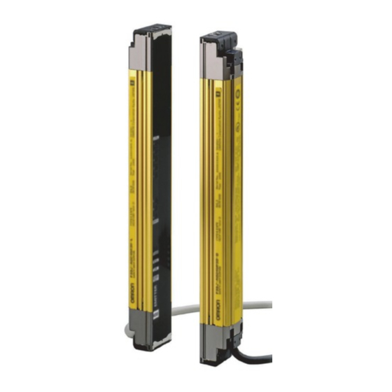
Safety light curtain
Hide thumbs
Also See for F3SJ-A series:
- Manual (46 pages) ,
- Quick start manual (8 pages) ,
- User manual (2 pages)
Table of Contents
Advertisement
Quick Links
Advertisement
Table of Contents

Related Manuals for Omron F3SJ-A series


Summary of Contents for Omron F3SJ-A series
- Page 1 F3SJ-A oooo P oo -TS Series User's Manual Safety Light Curtain Cat. No. SCHG-720D...
- Page 2 Introduction Thank you for purchasing the F3SJ Series Safety Light Curtain (hereinafter referred to as the "F3SJ" ). This is the instruction Manual describing the use of F3SJ. Always heed the following points when using the F3SJ: Be sure to have F3SJ be handled by a "Responsible Person" who is well aware of and familiar with the machine to be installed. The term "Responsible Person"...
- Page 3 •EC Type-Examination in accordance with the EU Machinery Directive, Type 4 ESPE (EN61496-1), Type 4 AOPD (prEN61496-2) •EMC Competent Body Certificate (Power supply for test: OMRON S82K) •TÜV SÜD Product Service Type Approval, Type 4 ESPE (EN61496-1), Type 4 AOPD (prEN61496-2), SIL1, 2, 3 (EN61508-1 through -7), Application: EN954-1 Category B,1,2,3,4 5.
- Page 4 PROFITS OR COMMERCIAL LOSS IN ANY WAY CONNECTED WITH THE PRODUCTS, WHETHER SUCH CLAIM IS BASED ON CONTRACT, WARRANTY, NEGLIGENCE, OR STRICT LIABILITY. In no event shall responsibility of OMRON for any act exceed the individual price of the product on which liability is asserted.
- Page 5 Performance data given in this document is provided as a guide for the user in determining suitability and does not constitute a warranty. It may represent the result of OMRON’s test conditions, and the users must correlate it to actual application requirements.
-
Page 6: Precautions On Safety
Introduction Precautions on Safety Precautions on Safety Regarding the alert symbols and meanings used for the safe uses In order to use the F3SJ safely, the precautions listed in this manual indicated by alert symbols and descriptions must be followed. Failure to follow all precautions and alerts may result in an unsafe use or operation. - Page 7 Introduction For installation Make sure to test the operation of the F3SJ after installation to verify that the F3SJ operates as intended. Make sure to stop the machine until the test is complete. Unintended function settings may cause a person to go undetected, resulting in serious injury.
- Page 8 Introduction Do not use the sensor system with mirrors in a retro-reflective configuration as shown below.Doing so may hinder detection. It is possible to use mirrors to "bend" the detection zone to a 90-degree angle. Reflector Reflector Position with retro-reflection Position with detection zone bent at 90 Perform an inspection for all F3SJ as described in "Chapter 5 Checklists".
- Page 9 Introduction Double or reinforced insulation from hazardous voltage must be applied to all input and output lines. Failure to do so may result in electric shock. Extension of the cable must be within a specified length. If it isn't, safety function may not work properly, resulting in danger.
-
Page 10: Precautions For Safe Use
Introduction Precautions for Safe Use Precautions for Safe Use Make sure to observe the following precautions that are necessary for ensuring safe use of the product. • Thoroughly read this manual and understand the installation procedures, operation check procedures, and maintenance procedures before using the product. - Page 11 Introduction Cleaning Do not use thinner, benzene, or acetone for cleaning, because they affect the product's resin parts and paint on the case. Object detection The F3SJ cannot detect transparent and/or translucent objects. F3SJ-A User’s Manual...
-
Page 12: Checking The Contents
Introduction Checking the Contents Before use, confirm that the items below were shipped with the product. If you find that an item is missing, please contact your local branch office or distributor. Product Quantity F3SJ-A -TS main unit Emitter x 1, Receiver x 1 Top/bottom mounting brackets 4 sets Intermediate mounting brackets... -
Page 13: How To Read This Manual (Explanation Of Symbols)
Introduction How to Read This Manual (Explanation of Symbols) Indicates the description of an essential point regarding a function, such as an important point regarding operation or advice on how to use it. Indicates the page number for related content. Indicates a reference for when there is trouble, or an explanation of difficult words. - Page 14 Introduction F3SJ-A User’s Manual...
-
Page 15: Table Of Contents
Introduction Contents Legislation and Standards READ AND UNDERSTAND THIS DOCUMENT Precautions on Safety Precautions for Safe Use viii Precautions for Correct Use viii Checking the Contents How to Read This Manual (Explanation of Symbols) Chapter1 Overview and Specifications Basic Configuration and Names Application Examples Detect the Approach to a Hazardous Zone Using Multiple Sets in Combination... - Page 16 Introduction External Device Monitoring Function Muting System Upgrading F3SJ for Muting System Standard Muting Mode Wiring Diagrams Installation Standard for Muting Sensors Installation Example 1 of Standard Muting Mode (using 2 muting sensors) Installation Example 2 of Standard Muting Mode (using 4 muting sensors) Override Function External Test Function Self-Test Function...
- Page 17 Introduction Wiring Procedure Chapter4 Input/Output Circuit and Applications Input/Output Circuit Wiring Examples Using only F3SJ Connecting 2 Muting Sensors Connecting 4 Muting Sensors Connecting to an F3SP-B1P Connecting to an F3SX-E-L2R Connecting to a G9SA-301 Connecting to a G9SA-300-SC Connecting to a G9SB-301-D Connecting to a G9SX-AD322-T15 Chapter5 Checklists...
- Page 18 Introduction F3SJ-A User’s Manual...
-
Page 19: Chapter1 Overview And Specifications
Chapter1 Overview and Specifications Basic Configuration and Names Application Examples Features Indicator Display Patterns Ratings Ratings/Specifications Model Name List/Response Times Power Cable Length F3SJ-A User’s Manual... -
Page 20: Basic Configuration And Names
Overview and Specifications Basic Configuration and Names This section describes the system configuration and part names of the F3SJ. Beam center-line mark Beam Emitter To attach or detach the cap and power cable, remove 4 screws shown above. Indicator Receiver Connection cable (Grey) Connection cable (Black) Extension cable... - Page 21 Overview and Specifications Component Model name Description Extension Cable with connector on one F39-JC A This extension cable is used to connect the F3SJ to a cable controller with discrete terminals (e.g. F3SX, G9SA, G9SB, G9SX) or to a safety processing system (e.g. DeviceNet safety).
-
Page 22: Application Examples
Overview and Specifications Application Examples Detect the Approach to a Hazardous Zone The F3SJ should be installed where workers require frequent access in order to perform tasks such as maintenance, and where physical barriers are difficult to install. Detect the Approach of a Person Detect a Person's Limbs F3SJ-A User’s Manual... -
Page 23: Using Multiple Sets In Combination
Overview and Specifications Using Multiple Sets in Combination By installing sensors on both sides of a machine as well as in front, you can move workpieces in and out more efficiently than when a physical barrier is installed. If the sensors are aligned in a U-shape, series-connection cables can be used between sets (up to 3 sets), so that only one control device is used, drastically reducing the amount of wiring in the panel. -
Page 24: Features
Overview and Specifications Features Protective Height Available in Incremental Sizes Protective height Series Protective height Detection capability F3SJ-A P20-TS 245mm to 2,495mm (in 15mm increments) Dia. 20mm F3SJ-A P25-TS 260mm to 2,500mm (in 20mm increments) Dia. 25mm Easy-to-Read Light Level and Error Mode Display LEVEL Incident light... -
Page 25: Indicator Display Patterns
Overview and Specifications Indicator Display Patterns Emitter Receiver LEVEL LEVEL LEVEL-5 (Green) LEVEL-5 (Green) LEVEL-4 (Green) LEVEL-4 (Green) 1. Incident light level LEVEL-3 (Orange) LEVEL-3 (Orange) 1. Incident light indicator level indicator LEVEL-2 (Orange) LEVEL-2 (Orange) LEVEL-1 (Orange) LEVEL-1 (Orange) ERROR-C (Red) ERROR- C (Red) 2. -
Page 26: Internal Indicator For Muting System
Overview and Specifications Internal Indicator for Muting System Shown below are internal indicator statuses while the keycap for muting is being attached. Indicators Description Blinking Incident light level LEVEL-1 to 5 Indication status of LEVEL-1 to 5 shows the incident light level indicator status of the F3SJ. -
Page 27: Ratings
Overview and Specifications Ratings Ratings/Specifications In the model names in this table, the contain the 4-digit number indicating the protective height (mm). F3SJ-A P20-TS F3SJ-A P25-TS Detection capability Opaque objects Opaque objects Diameter 20mm Diameter 25mm Beam gap 15mm 20mm Number of beams 16 to 166 13 to 125... - Page 28 Overview and Specifications F3SJ-A P20-TS F3SJ-A P25-TS Indicators Emitter Incident light level indicators (green LED x 2, orange LED x 3): ON based on the amount of incident light Error mode indicators (red LED x 3): Blink to indicate error details Power indicator (green LED x 1): ON while power is ON Lockout indicator (yellow LED x 1): Blinks when in lockout External device monitoring indicator (muting input 1 indicator), Test indicator (muting input 2...
-
Page 29: Model Name List/Response Times
Overview and Specifications F3SJ-A P20-TS F3SJ-A P25-TS Weight (packaged) - F3SJ-A P20-TS/F3SJ-A P25-TS Weight (g)=(protective height) x 1.5+ α The values for α are as follows: When protective height is between 245 and 596mm, α=1100 When protective height is between 600 and 1130mm, α=1500 When protective height is between 1136 and 1658mm, α=2000 When protective height is between 1660 and 2180mm, α=2400 When protective height is between 2195 and 2500mm, α=2600... - Page 30 Overview and Specifications Response time Response time F3SJ-A P20-TS F3SJ-A P25-TS Number of beams (ON to OFF) (OFF to ON) F3SJ-A0575P20-TS F3SJ-A0760P25-TS 38 beams 12ms 48ms F3SJ-A0590P20-TS F3SJ-A0780P25-TS 39 beams 12ms 48ms F3SJ-A0605P20-TS F3SJ-A0800P25-TS 40 beams 12ms 48ms F3SJ-A0620P20-TS F3SJ-A0820P25-TS 41 beams 12ms 48ms...
- Page 31 Overview and Specifications Response time Response time F3SJ-A P20-TS F3SJ-A P25-TS Number of beams (ON to OFF) (OFF to ON) F3SJ-A1295P20-TS F3SJ-A1720P25-TS 86 beams 17.5ms 70ms F3SJ-A1310P20-TS F3SJ-A1740P25-TS 87 beams 17.5ms 70ms F3SJ-A1325P20-TS F3SJ-A1760P25-TS 88 beams 17.5ms 70ms F3SJ-A1340P20-TS F3SJ-A1780P25-TS 89 beams 17.5ms 70ms...
- Page 32 Overview and Specifications Response time Response time F3SJ-A P20-TS F3SJ-A P25-TS Number of beams (ON to OFF) (OFF to ON) F3SJ-A2015P20-TS 134 beams 20.0ms 80ms F3SJ-A2030P20-TS 135 beams 20.0ms 80ms F3SJ-A2045P20-TS 136 beams 20.0ms 80ms F3SJ-A2060P20-TS 137 beams 20.0ms 80ms F3SJ-A2075P20-TS 138 beams 20.0ms...
-
Page 33: Power Cable Length
Overview and Specifications Power Cable Length Extension of power cable must be the length shown below or shorter: In case F3SJ is directly connected to external power supply, or connected to G9SA-300-SC Condition Single 2 connected 3 connected Incandescent display lamps are used by auxiliary output and/or external indicator output Incandescent display lamps are not used 100m... - Page 34 Overview and Specifications F3SJ-A User’s Manual...
-
Page 35: Chapter2 System Configuration And Functions
Chapter2 System Configuration and Functions How to Select a System System Selection Function List Basic System Wiring Diagrams External Test Function Self-Test Function Auxiliary Output (Non-Safety Output) Resetting Lockout External Device Monitoring Function Muting System Upgrading F3SJ for Muting System Standard Muting Mode Wiring Diagrams Installation Standard for Muting Sensors... -
Page 36: How To Select A System
System Configuration and Functions How to Select a System System Selection The required system configuration depends on the functions to be used. Decide the system to use based on the following: When not using the muting function ... Basic system When using the muting function ... -
Page 37: Basic System
System Configuration and Functions Basic System Basic system indicates the F3SJ with its default factory settings. The basic system provides basic safety light curtain functions. Most functions can be used without performing additional configuration. Wiring Diagrams Wiring using external device monitoring function (Grey) Communication line (+) (Pink) Communication line (-) - Page 38 System Configuration and Functions Wiring When External Device Monitoring Function Is Not Used The external device monitoring function is disabled by connecting auxiliary output 1 and external device monitoring input as shown below. (Grey) Communication line (+) (Pink) Communication line (-) +24V DC Power supply...
-
Page 39: External Test Function
System Configuration and Functions External Test Function This function forcibly stops the emission using an external signal. It can be used to verify that a safety system should properly stop when F3SJ is interrupted. To stop the emission, apply 9 to 24V to the emitter's test input line. The voltage must be applied for a period 4 times that of Toff or longer. - Page 40 System Configuration and Functions •Failure of safety output circuit •Broken or short-circuited cable Error indication patterns and causes of errors p.112 How to reset lockout: See p.23 for basic system and p.44 for muting system For information about lockout, see p.125 Waveform of Safety Outputs When the F3SJ is receiving light, the safety outputs cyclically turn OFF as shown below to test the output circuit.
-
Page 41: Auxiliary Output (Non-Safety Output)
System Configuration and Functions Auxiliary Output (Non-Safety Output) The auxiliary output is used to monitor the status of the F3SJ. This output can be connected to a device such as a relay, indication lamp, programmable controller, etc. Do not use the auxiliary output or external indicator output for safety applications. Human body may not be detected when F3SJ fails, resulting in serious injury. -
Page 42: External Device Monitoring Function
System Configuration and Functions External Device Monitoring Function This function detects malfunctions, such as welding, in external relays (or contactors) that control the hazardous zone of a machine. This function constantly monitors that a specified voltage is applied to the receiver's external device monitoring input line, and enters lockout state when an error occurs. -
Page 43: Muting System
System Configuration and Functions Muting System The muting function temporarily disables the safety function of the F3SJ, keeping the safety outputs ON even if beams are blocked. This makes it possible to install safety light curtains for AGV passage, enabling both safety and productivity. -
Page 44: Upgrading F3Sj For Muting System
The muting sensor is the sensor that is the trigger for temporarily disabling the F3SJ's safety functions. Through-beam or retro-reflective photoelectric sensors, proximity sensors, or limit switches can be used as muting sensors. (recommendation: OMRON E3Z series, E2E series, D4N series)Use those with PNP outputs or N.O. type contacts. -
Page 45: Standard Muting Mode
System Configuration and Functions • Where to attach the included labels F39-CN6 key cap for muting includes internal indicator label (1). When muting system is used, affix the label (1) in a location so that the arrows are aligned with the portion of the internal indicator display indicated by the shaded zones. - Page 46 System Configuration and Functions End Conditions If either of the following conditions are satisfied, the muting state is released. •Muting input 1 or 2 turns OFF at T3 or later (0.1s or later). •The muting continuation time exceeds the muting time limit of T2 (60s). T3(0.1s) max.
-
Page 47: Wiring Diagrams
System Configuration and Functions Wiring Diagrams Wiring When Using Muting and External Device Monitoring Function (Grey) Communication line (+) (Pink) Communication line (-) Power supply (connect to 0V if a switch is not required) : External test switch : Lockout reset switch(connect to 24V if a switch is not required) : Contact by muting sensor A1 : Contact by muting sensor B1 K1,K2 : Relay or other device that controls hazardous parts of the machine... - Page 48 System Configuration and Functions Ref.: Minimum Wiring Required to Check the Operation of the F3SJ When Using the Muting Function (Wiring that does not use the external device monitoring function) M1 *1 *2 (Grey) Communication line (+) (Pink) Communication line (-) +24V DC Power supply...
-
Page 49: Installation Standard For Muting Sensors
System Configuration and Functions Installation Standard for Muting Sensors •Set the muting sensors so that they can detect all of the passing detection objects (palettes, automobiles, etc.). Do not install in a position so that only the front or rear end of the detection object is detected. - Page 50 System Configuration and Functions The muting sensor outputs are turned ON (muting inputs are HIGH) and the safety function of the F3SJ is disabled. Hazardous zone Reflector F3SJ Workpiece Reflector F3SJ When muting sensors A1 and B1 are turned ON in this order, the muting function is enabled. In this state, the safety function of the F3SJ is disabled.
- Page 51 System Configuration and Functions The muting function is released Hazardous zone F3SJ Reflector Workpiece Reflector F3SJ Muting sensor A1 is turned OFF, the muting function is released, and the safety function of the F3SJ is enabled. Installation Distance The minimum distance, D1 [ m ], required for muting sensors to keep the muting function enabled is <...
- Page 52 System Configuration and Functions Wiring Diagrams Using a photoelectric switch as a muting sensor Using an N.O contact type switch as a muting sensor Reflector A1, B1: N.O contact type switch A1, B1: Regressive reflection photoelectric switch + 24 V DC - PNP Output Power - ON when Interrupted...
-
Page 53: Installation Example 2 Of Standard Muting Mode (Using 4 Muting Sensors)
System Configuration and Functions •T3: Muting input time with allowable waveform cracks This is the maximum value for the waveform cracks allowed for muting input 1 and 2 when muting is in effect. It is set to 0.1 sec. Installation Example 2 of Standard Muting Mode (using 4 muting sensors) This installation example uses 4 through-beam type photoelectric sensors as muting sensors. - Page 54 System Configuration and Functions The muting sensors are blocked and the safety function of the F3SJ is disabled Hazardous zone F3SJ Workpiece Muting sensors A1 and B1 are turned OFF but A2 and B2 are ON, so the muting function is still working.
- Page 55 System Configuration and Functions This distance must prevent the muting function from being enabled by a person passing through the muting sensors. Also, install the F3SJ and muting sensors so that a workpiece passes through all muting sensors before the next workpiece arrives at the first muting sensor. Workpiece Workpiece Workpiece...
- Page 56 System Configuration and Functions Timing Chart T3(0.1s ) max. Muting sensor A1 T1min to T1max T3(0.1s ) max. Muting sensor B1 T3(0.1s ) max. Muting sensor A2 T3(0.1s ) max. Muting sensor B2 T2 max. 0.15s max. *1 Enabled Muting state Disabled Blinking Muting lamp...
- Page 57 System Configuration and Functions Reference: Bidirectional Muting Shown below is an example of bidirectional muting with 4 retro-reflective photoelectric sensors. It can be used for applications of workpiece approaching from both directions. Connect outer muting sensors A1 and A2 to the muting input 1 and inner muting sensors B1 and B2 to the muting input 2.
- Page 58 System Configuration and Functions Reference: Preventing light interference of muting sensor When a photoelectric sensor is used as a muting sensor, light interference may cause a muting error of F3SJ. Light interference may occur due to: Reflected light Direct light Light from other F3SJ A1 B1 F3SJ...
-
Page 59: Override Function
System Configuration and Functions Override Function The override function forcibly turns the safety outputs ON when the muting start condition is not satisfied. If a workpiece stops while passing through the detection zone of the F3SJ, as shown below, causing a muting error, the normal state cannot be recovered unless the workpiece is removed from the muting sensors and the detection zone of the F3SJ. - Page 60 System Configuration and Functions Override End Conditions When either of the following conditions is satisfied, the function is released. •When 60 seconds has elapsed under the override state •All muting sensors are turned OFF •When the reset input is turns from OFF to ON and/or the test input turns from ON to OFF Override state can be released if a sensor transitions to lockout as well.
-
Page 61: External Test Function
System Configuration and Functions External Test Function This function forcibly stops the emission using an external signal. It can be used to verify that the safety system should stop properly when the F3SJ is interrupted. To stop the emission, apply 9 to 24V to the emitter's test input line. The voltage must be applied for a period 0.3s plus 4 times of Toff or longer. -
Page 62: Auxiliary Output (Non-Safety Output)
System Configuration and Functions Auxiliary Output (Non-Safety Output) The auxiliary output is used to monitor the status of the F3SJ. This output can be connected to a device such as a relay, indication lamp, programmable controller, etc. Do not use the auxiliary output or external indicator output for safety applications. Human body may not be detected when F3SJ fails, resulting in serious injury. -
Page 63: Chapter3 Wiring/Installation
Chapter3 Wiring/Installation Installation Conditions Detection Zone and Approach Safety Distance Distance from Reflective Surfaces Mutual Interference Prevention Series Connection Connection Procedure Attaching External Indicators Connection Procedure Output Operation Dimensions When Using Standard Mounting Brackets When Using Optional Mounting Brackets When Using Spatter Protection Covers Mounting a Protect Bar Mounting an Environment-Resistant Case Mounting... -
Page 64: Installation Conditions
Wiring/Installation Installation Conditions Detection Zone and Approach Install a protective structure so that the hazardous part of a machine can only be reached by passing through the sensor's detection zone. Install the sensors so that part of the person is always present in the detection zone when working in a machine's hazardous zones. -
Page 65: Safety Distance
Wiring/Installation Safety Distance The safety distance is the distance that must be set between the F3SJ and a machine's hazardous part to stop the hazardous part before a person or object reaches it. The safety distance varies according to the standards of each country and the individual specifications of each machine. Always refer to the relevant standards. - Page 66 Wiring/Installation In case of horizontal approach of a human body to F3SJ's detection zone Use K = 1,600mm/s and C = (1200 - 0.4 x H) in formula (1) for calculation.Note that C must not be less than 850mm. Safety distance (S) S = 1,600mm/s x (Tm + Ts) + 1200 - 0.4 x H Hazard •S = Safety distance (mm)
-
Page 67: Distance From Reflective Surfaces
Wiring/Installation Distance from Reflective Surfaces Install the sensor system so that it is not affected by reflective surfaces. Failure to do so may hinder detection, resulting in serious injury. Install the sensor system at distance D or further from highly reflective surfaces such as metallic walls, floors, ceilings, or workpieces, as shown below. -
Page 68: Mutual Interference Prevention
Wiring/Installation Mutual Interference Prevention Do not use the sensor system with mirrors in a retro-reflective configuration. Doing so may hinder detection. It is possible to use mirrors to "bend" the detection zone to a 90-degree angle. When using more than 1 set of F3SJ, install them so that mutual interference does not occur, such as by configuring series connections or using physical barriers between adjacent sets. - Page 69 Wiring/Installation 2. Alternate the direction of emission between 2 sets (alternation) Aligned vertically Aligned horizontally Emitter Receiver Emitter Receiver Emitter Receiver Emitter Receiver Aligned fore and aft Receiver Emitter Emitter Receiver If 2 sets are installed near each other, reflection from the surfaces may cause mutual interference. 3.
-
Page 70: Series Connection
Wiring/Installation Series Connection From 2 to 3 sets of F3SJ can be series-connected. Series connection allows them to be used as a a safety light curtain, requiring only 1 set to be wired to a controller and preventing mutual interference. If any 1 set of series-connected F3SJ is blocked, both of the safety outputs turn OFF. - Page 71 Wiring/Installation Connect an emitter to another emitter, and a receiver to another receiver, as shown below. Do not face different models of emitters and Do not series-connect an emitter and receiver. receivers toward each other. They will enter They will enter lockout state. lockout state or will be unable to detect objects.
-
Page 72: Connection Procedure
Wiring/Installation Connection Procedure When Using the F39-JJR L Series Connection Cable for Close Contact (sold separately) Remove the connection cable of the secondary-side F3SJ. (driver comes with F39-JJR L) Remove the cap from the secondary-side F3SJ. Use the F39-JJR L series connection cable for close contact to connect them. Emitter power supply 1. - Page 73 Wiring/Installation When Using the F39-JJR3W Series Connection Cable for Extension (sold separately) Remove the caps from the primary sensor. (driver comes with key cap for muting) Use the F39-JJR3W series connection cable for extension to connect them. When changing the connection distance between the F3SJ, connect a F39-JC B Cable with connectors on both ends (sold separately).
-
Page 74: Attaching External Indicators
Wiring/Installation Attaching External Indicators An external indicator can be connected and turned ON based on the operation of the F3SJ. Indicators can be attached to emitters and/or receivers. Example: • Indicate that the F3SJ is in lockout • Indicate that a machine is stopped (safety output is OFF) •... -
Page 75: Output Operation
Wiring/Installation - Attaching/detaching of a cap or a series-connection cable may cause misalignment of rubber grommet in a connector assembly. Press the grommet to the bottom of the connector and attach the connector F3SJ again. Rubber Grommet Rubber Grommet Rubber Grommet in Right Position Misaligned Grommet Output Operation The external indicator output 1 (on the receiver side) is configured as "safety output reverse output... -
Page 76: Dimensions
Wiring/Installation Dimensions When Using Standard Mounting Brackets Backside Mounting Top/bottom mounting bracket Intermediate mounting bracket 2-Top/bottom mounting brackets 2-Mounting holes (Unit: mm) 4-M5 Intermediate mounting 2-M5 bracket 2-Mounting holes Beam 4-Mounting holes dia. 6 dia. 6.5 2-Mounting holes dia. 9 M12 Waterproof connector dia.15 Bracket mounting procedure (Mounting) p.79... - Page 77 Wiring/Installation Side Mounting Top/bottom mounting bracket Intermediate mounting bracket 2-Top/bottom (Unit: mm) mounting brackets 2-Mounting holes Beam dia. 6 4-Mounting holes dia. 6.5 2-Mounting holes dia. 9 M12 Waterproof connector Bracket mounting procedure (Mounting) p.79 F3SJ-A User’s Manual...
- Page 78 Wiring/Installation Dimensions A to E C + 74 C + 46.5 4-digit number of the model name (protective height) C - 20 Depends on the protective height. See the table below. Dimension E Number of intermediate Protective height mounting brackets 0245 to 0596 0600 to 1130 1136 to 1658...
-
Page 79: When Using Optional Mounting Brackets
Wiring/Installation When Using Optional Mounting Brackets F39-LJ2 Side-mounting Optional Bracket F39-LJ2 37.6 (Unit: mm) 4-M5 dia. 6.5 dia. 9 Material: Stainless steel Dimensions A to C C + 74 C + 39.5 4-digit number of the model name (protective height) F3SJ-A User’s Manual... - Page 80 Wiring/Installation F39-LJ3 Free-location Mounting Bracket Backside mounting (Unit: mm) 6-M5 Material: Zinc die-cast F3SJ-A User’s Manual...
- Page 81 Wiring/Installation Side mounting (when using intermediate brackets for side mounting) (Unit: mm) 6-M5 Material: Zinc die-cast/stainless steel F3SJ-A User’s Manual...
- Page 82 Wiring/Installation Side mounting (when not using intermediate brackets for side mounting) (Unit: mm) 6-M5 2-dia. 5.5 53 42 Material: Zinc die-cast When performing side mounting without using intermediate brackets for side mounting, F39-LJ3 brackets cannot be used in combination with standard brackets. F3SJ-A User’s Manual...
- Page 83 Wiring/Installation Dimensions B, C, and F C - 90 4-digit number of the model name (protective height) Depends on the protective height. See the table below. Dimension F Number of intermediate Protective height mounting brackets 245 to 440 443 to 785 794 to 1140 1145 to 1490 1495 to 1840...
- Page 84 Wiring/Installation F39-LJ4 Top/bottom Mounting Bracket B Backside mounting F39-LJ4 Use standard brackets (Unit: mm) 4-M5 19(*1) Material: Stainless steel *1 A mounting width of 18 to 20 can be supported when mounting with M5 screws. Dimensions A to C C + 109 C + 66 4-digit number of the model name (protective height) F3SJ-A...
- Page 85 Wiring/Installation Side mounting F39-LJ4 Use standard brackets (Unit: mm) 4-M5 19(*1) Material: Stainless steel *1 A mounting width of 18 to 20 can be supported when mounting with M5 screws. Dimensions A to C C + 109 C + 66 4-digit number of the model name (protective height) F3SJ-A User’s Manual...
- Page 86 Wiring/Installation F39-LJ5 Replacement Bracket for F3SN Use these replacement brackets for an F3SN with a small protective height. (These brackets are designed for use with the F3SN's mounting holes.) Inward-facing mounting Use standard brackets F39-LJ5 (Unit: mm) 4-M5 dia. 6.5 dia.
- Page 87 Wiring/Installation Outward-facing mounting Use standard brackets F39-LJ5 (Unit: mm) 4-M5 dia. 6.5 19.9 dia.9 Material: Stainless steel Dimensions A to C C + 65 C + 34 4-digit number of the model name (protective height) F3SJ-A User’s Manual...
- Page 88 Wiring/Installation Inward + outward-facing mounting Use standard F39-LJ5 brackets (Unit: mm) 4-M5 dia. 6.5 19.9 dia.9 Material: Stainless steel Dimensions A to C C + 44 C + 12 4-digit number of the model name (protective height) F3SJ-A User’s Manual...
- Page 89 Wiring/Installation F3SN replacement correspondence table (F3SN mounting holes can be used without modification) •When replacing F3SN- P25 with F3SJ-A P25-TS F3SN Replacement F3SJ Replacement method using F39-LJ5 Model name Protective height Model name Protective height F3SN- 0187P25 F3SN- 0217P25 F3SJ-A0260P25-TS Inward-facing mounting F3SN- 0232P25 F3SJ-A0260P25-TS...
- Page 90 Wiring/Installation F39-LJ8 Space-saving Mounting Bracket Brackets that can save mounting space for top and bottom Backside mounting Use standard F39-LJ8 brackets (Unit: mm) 4-M5 Material: Stainless steel Dimensions A to C C + 23 C - 10.3 4-digit number of the model name (protective height) The F39-LJ8 and intermediate mounting brackets cannot be mounted simultaneously, so set the protective height to 600mm or less.
- Page 91 Wiring/Installation F39-LJ11 Top/bottom Mounting Bracket C Use standard brackets (Unit: mm) Hole size for mounting 4-M5 54.5 C (Protective height) 54.5 4-Mounting holes Material: Stainless steel Dimensions A to C C + 109 C + 69 4-digit number of the model name (protective height) F3SJ-A User’s Manual...
-
Page 92: F39-A01Po-Pac External Indicator Set
Wiring/Installation F39-A01P -PAC External Indicator Set •F39-A01P -PAC (Unit: mm) dia. 30 dia. 9 dia. 6.5 Material: Stainless steel When Using Spatter Protection Covers Dimensions of the Spatter Protection Cover F39-HJ (Unit: mm) -10 mm Material: PC (protective cover) Assembly Dimensions (Unit: mm) F3SJ-A User’s Manual... -
Page 93: Mounting A Protect Bar
Wiring/Installation Mounting a Protect Bar External Dimensions of Protect Bar F39-PJ Backside mounting (Unit: mm) Hole size for mounting 3-M5 Protection Bracket (2) Hex. Bolt Using M5 Using M6 and M8 with Washer and Hole dia.9 (13.75) 2-M8 dia.6.5 16.5 3.75 4-M5 6.25... - Page 94 Wiring/Installation Side mounting (Unit: mm) Hole size for mounting 3-M5 Protection Bracket (2) Hex. Bolt Using M5 Using M6 and M8 dia.9 with Washer and Hole (13.75) 2-M8 dia.6.5 16.5 3.75 6.25 4-M5 (37) 2-M6 Protection Bracket (4) *1 (Protective 10 20 height) dia.5.5...
-
Page 95: Mounting An Environment-Resistant Case
Wiring/Installation Mounting an Environment-Resistant Case External Dimensions of Environment-Resistant Case F39-EJ Backside mounting (Unit: mm) Hole size for mounting dia. 60.5 Using M5 Using M6 and M8 dia. 9 2-M8 dia.6.5 4-M5 13.5 2-M6 (Protective height) 2-Mounting brackets (F39-EJ-R) *1 Mounting Bracket (F39-EJ-R) is not included. Material: Acrylic resin, nitrile rubber, stainless steel Dimensions A to D C+108... - Page 96 Wiring/Installation Side mounting (Unit: mm) Hole size for mounting dia. 60.5 Using M5 Using M6 and M8 dia. 9 2-M8 dia. 6.5 4-M5 13.5 2-M6 (Protective height) 2-Mounting brackets (F39-EJ-S) *1 Mounting Bracket (F39-EJ-S) is not included. Material: Acrylic resin, nitrile rubber, stainless steel Dimensions A to D C+108 C+76...
-
Page 97: Mounting
Wiring/Installation Mounting The procedures for using standard mounting brackets (included) are explained in this section. Top/Bottom Mounting Brackets Mounting screws (M5x18) x 4 Top/bottom mounting bracket (2) x 4 Top/bottom mounting bracket (1) x 4 Top/bottom mounting bracket (3) x 4 *1 The quantities shown here are the number of Mounting screws (M3x8) x 8 parts included in 1 top/bottom mounting bracket set... -
Page 98: Mounting Procedure
Wiring/Installation Mounting Procedure Attach the top/bottom mounting brackets. Place top/bottom mounting bracket (2) in the screw hole at the top/bottom of the F3SJ, and fasten it using the included screw (M5x18). Insert the bracket's protrusion into the groove on the case when attaching. - Page 99 Wiring/Installation Attach the intermediate mounting brackets (for backside mounting). For backside mounting, first lightly attach intermediate mounting bracket (1) to the equipment, wall surface, etc. Then, attach intermediate brackets (1) and (4) to the bracket that was lightly attached to the case in step 2 above, and lightly tighten them using the included mounting screws (M4x25).
- Page 100 Wiring/Installation Fasten to equipment. Attach top/bottom mounting bracket (1) to the equipment, wall surface, etc. If you are using an intermediate mounting bracket for side mounting, also attach the side-mounting intermediate bracket to the equipment, wall surface, etc. After the F3SJ is mounted, securely tighten the mounting screws (M3x10) that were lightly tightened in step 2 above.
-
Page 101: Adjustment Procedure
Wiring/Installation Adjustment Procedure Check the following points: - The optical surface of the emitter and receiver should be clean. - There should be no interrupting object in the detection zone of the F3SJ. Adjust the emitter's beams. Adjust the angle of the emitter while checking the incident light level indicator, and align the emitter so that it faces the center position where the incident light level indicator turns ON. -
Page 102: Wiring
Wiring/Installation Wiring Wiring Precautions Double or reinforced insulation from hazardous voltage must be applied to all input and output lines. Failure to do so may result in electric shock. Connect the load between the output and 0V line. (PNPoutput) Connecting between the output and +24V line is dangerous because the operation mode is reversed to "ON when blocked". -
Page 103: Power Supply Unit
"circuit protection such as a fuse is used to limit the current, which has a rating of 4.2A max." (24VDC power supply). Recommended power supply: OMRON S82K (15 W, 30 W, 50 W, 90 W type), S8VS (60 W type), S82J (10 W, 25 W, 50 W type) These products are approved by UL listing (UL508, class 2 power supply), CE marking compatible (EMC/Low Voltage Directive). -
Page 104: Wiring Procedure
Wiring/Installation Wiring Procedure Connect an emitter cable (F39-JC -L, grey, sold separately) to the emitter's connection cable (grey). Connect a receiver cable (F39-JC -D, black, sold separately) to the receiver's connection cable (black). Connect the 0V line of the power supply directly to the protective earth (PE). To ensure proper wiring, check that the color of the cable matches the color of the connector's resin cover (emitter: grey, receiver: black). - Page 105 Wiring/Installation Series Connection Cable for Close Contact(F39-JJR L, sold separately) 33.4 33.4 (Unit: mm) Set model name For emitter For receiver L (mm) F39-JJR06L F39-JJR06L-L Grey cable F39-JJR06L-D Black cable F39-JJR15L F39-JJR15L-L F39-JJR15L-D Series Connection Cable for Extension (F39-JJR3W, sold separately) (Unit: mm) 33.4 39.5...
- Page 106 Wiring/Installation Connection Cable (F39-JJR3K, sold separately) The connection cable is a standard included product. Purchase a replacement when damaged or lost. (Unit: mm) 33.4 Connector 21.4 Body color: Black M12 Waterproof connector (plug) Insulated vinyl round cable dia. 6, shielded 8-wire (Cross section of conductor: 0.15mm / Insulator diameter: 1mm) Set model name...
- Page 107 Wiring/Installation Internal wiring diagram (F39-JC B-L, F39-JC B-D) Connected to connection cable and Connected to single-end connector cable, Cable Cable with connectors on both ends with connectors on both ends, Controller F3SP-B1P White White Brown Brown Green Green Yellow Yellow Grey Grey Pink...
- Page 108 Wiring/Installation Internal wiring diagram (F39-JC C-L) Connected to emitter's connection cable Connected to controller G9SA-300-SC and Cable with connectors on both ends Blue Brown Brown Green Yellow Grey Green Pink Blue Grey Pink Female Male Shield Shield Internal wiring diagram (F39-JC -D) Connected to receiver's connection cable Connected to controller G9SA-300-SC and Cable with connectors on both ends...
- Page 109 Wiring/Installation Universal indicator cable: A cable for connection with a commercial indicator (optional: F39-JJ3N) Vinyl insulated round cable: Dia. 6 33.4 8-cord (conductor cross section: 0.15mm /insulation diameter: 1mm) (10) (10) 21.4 3000 Connector F3SJ-A User’s Manual...
- Page 110 Wiring/Installation F3SJ-A User’s Manual...
-
Page 111: Chapter4 Input/Output Circuit And Applications
Chapter4 Input/Output Circuit and Applications Input/Output Circuit Wiring Examples Using only F3SJ Connecting 2 Muting Sensors Connecting 4 Muting Sensors Connecting to an F3SP-B1P Connecting to an F3SX-E-L2R Connecting to a G9SA-301 Connecting to a G9SA-300-SC Connecting to a G9SB-301-D Connecting to a G9SX-AD322-T15 F3SJ-A User’s Manual... -
Page 112: Input/Output Circuit
Input/Output Circuit and Applications Input/Output Circuit The numbers in white circles indicate the connector's pin numbers. The black circles indicate connectors for series connection. The words in brackets [ ] indicate the signal name for muting system. Indication External indicator output 2 +24V DC Brown Brown... -
Page 113: Wiring Examples
Input/Output Circuit and Applications Wiring Examples Some examples of a motor control system using F3SJ are shown. The category of these systems defined by EN954-1 is 4. Using only F3SJ •Use of relay contact welding detection is possible without a controller or relay unit - Using external device monitoring function Emitter Receiver... -
Page 114: Connecting 2 Muting Sensors
Input/Output Circuit and Applications Connecting 2 Muting Sensors • Attaching a key cap for muting (F39-CN6) enables the muting function to be used Attaching the key cap for muting (F39-CN6) p.26 Muting lamp (external indicator) - Using external device monitoring function Emitter Receiver F39-JC A-L... -
Page 115: Connecting 4 Muting Sensors
Input/Output Circuit and Applications Connecting 4 Muting Sensors • Attaching a key cap for muting (F39-CN6) enables the muting function to be used Attaching the key cap for muting (F39-CN6) p.26 Muting lamp (external indicator) - Using external device monitoring function Emitter Receiver :External test switch... -
Page 116: Connecting To An F3Sp-B1P
Input/Output Circuit and Applications Connecting to an F3SP-B1P •Reduced wiring due to connector connection •Safety relay included Emitter Receiver - Using external device monitoring function Model F39-JC Model F39-JC Test Reset Auxiliary output Safety Safety Output2 K1 Output1 External device monitoring T31 T32 Model F3SP-B1P... -
Page 117: Connecting To An F3Sx-E-L2R
Input/Output Circuit and Applications Connecting to an F3SX-E-L2R •Emergency stop switch can be connected •Door switch, two hand control, single beam, or relay unit can be used in combination with F3SX •Various settings can be changed and input/output terminals can be monitored using the setting support software for F3SX L2 Module - F3SJ settings... - Page 118 Input/Output Circuit and Applications •Using a branch connector Connector connection is possible using a cable with connectors on both ends and branch connector for safety light curtains. F3SJ F3SJ Receiver Emitter Branch connector for safety light curtains F39-CN5 Grey Black Cable with connectors on both ends: Cable with connectors on both ends F39-JC...
-
Page 119: Connecting To A G9Sa-301
Input/Output Circuit and Applications Connecting to a G9SA-301 Emitter Receiver - F3SJ settings - Does not use external device monitoring function - G9SA-301 settings - Manual reset mode - Using feedback loop - Using emergency stop switch Model F39-JC Model F39-JC Communication line (+) (Grey) Communication... -
Page 120: Connecting To A G9Sa-300-Sc
Input/Output Circuit and Applications Connecting to a G9SA-300-SC •Reduced wiring due to connector connection - F3SJ settings - Not using external device monitoring - G9SA-300-SC settings Emitter Receiver - Manual reset mode - Using feedback loop Model F39-JC Model F39-JC +DC24V (Note 2) A1 A2 T11 T12 H1... -
Page 121: Connecting To A G9Sb-301-D
Input/Output Circuit and Applications Connecting to a G9SB-301-D •Thin (22.5mm thick) Emitter Receiver - F3SJ settings - Does not use external device monitoring function - G9SB-301-D settings - Manual reset mode - Using feedback loop F39-JC A-L F39-JC A-D Communication line (+) (Grey) Communication line (-) (Pink) -
Page 122: Connecting To A G9Sx-Ad322-T15
Input/Output Circuit and Applications Connecting to a G9SX-AD322-T15 •Can be configured for partial control and total control •Can be extended to connect a door switch or a relay unit Receiver Emitter - F3SJ settings - Not using external device monitoring - G9SX-AD322-T15 settings - Auto reset mode - Using feedback loop... -
Page 123: Chapter5 Checklists
Chapter5 Checklists Pre-Operation Checklists Maintenance Checklists F3SJ-A User’s Manual... -
Page 124: Pre-Operation Checklists
Checklists Pre-Operation Checklists Make sure to test the operation of the F3SJ after installation to verify that the F3SJ operates as intended. Make sure to stop the machine until the test is complete. Unintended function settings may cause a person to go undetected, resulting in serious injury. - Page 125 Checklists A secondary sensor farthest from its power supply has either of the followings: - Cap - Key cap for muting - Muting lamp (set of lamp and cable) Neither connector, cap, or bracket must be loose. Auxiliary outputs 1, and external indicator outputs 1 and 2 must not be used as safety output. Power supply's 0V must be grounded.
-
Page 126: Maintenance Checklists
Checklists Maintenance Checklists Perform daily and 6-month inspection for the F3SJ. Otherwise, the system may fail to work properly, resulting in serious injury. Do not try to disassemble, repair, or modify this product. Doing so may cause the safety functions to stop working properly. - Page 127 Checklists Checking that Hazardous Parts Stop While the Machine Operates The hazardous parts are movable when nothing is in the detection zone. The hazardous parts stop immediately when a test rod is inserted into the detection zone at 3 positions: "directly in front of the emitter", "directly in front of the receiver", and "between the emitter and receiver".
- Page 128 Checklists F3SJ-A User’s Manual...
-
Page 129: Chapter6 Appendix
Chapter6 Appendix Troubleshooting Accessories (Sold Separately) Glossary Related Standards Revision History F3SJ-A User’s Manual... -
Page 130: Troubleshooting
Appendix Troubleshooting Lockout State If F3SJ detects any failure, it keeps safety output OFF and transitions to lockout state. Under lockout state, an emitter and a receiver set lockout indicator and OFF indicator blinking respectively, and F3SJ that detected the failure sets an error mode indicator ON or blinking based on the failure. Solve the problems based on the table below.*1 Eliminate the cause of the problem. - Page 131 Appendix Blink Emitter Receiver Error code Error Description Cause Solution 10, 11 Mutual Disturbance light is received. Block the disturbance light. p.50 interference error The receiver is receiving light See Chapter 3 "Mutual emitted from another photoelectric Interference Prevention". switch or F3SJ. p.50 19, *2 Power supply...
- Page 132 Appendix Emitter Receiver Error code Error Description Cause Solution Excessive number Total number of beams of F3SJs Rearrange series connection so of beams under series connection exceeds that total number of beams of 240. series connection should not exceed 240. Excessive number Four or more sensors are Number of F3SJs under series...
- Page 133 Appendix Emitter Receiver Error code Error Description Cause Solution 5B, 5E Incorrect wiring of The reset input line is not properly Check wiring of reset input line reset input line/ wired. and emitter side white line. p.19 white wire on the Emitter side white line is short- emitter side circuited to 24V...
-
Page 134: Problem Under Other State Than Lockout
Appendix Emitter Receiver Error code Error Description Cause Solution Error code Effect of noise. Effect of noise is excessive. Check the noise level in the other than surrounding environment. those above Lockout of other Failure occurred in another F3SJ Solve the problem of F3SJ in a F3SJ in the series under series connection. - Page 135 Appendix • Light intensity level indicators do not turn ON even if a beam receives light, while only the power indicator, OFF output indicator, and receiver's error code A are being turned ON Emitter Receiver Cause Action Communication line is broken between an emitter Perform the proper wiring.
-
Page 136: Accessories (Sold Separately)
Appendix Accessories (Sold Separately) Cable with connector on one end (2 cables per set, for emitter and receiver) Appearance Model name Cable length Specifications F39-JC3A M12 connector (8-pin) - 8 wires + Shield F39-JC7A F39-JC10A F39-JC15A F39-JC20A Cable with connectors on both ends: For connection with F3SP-B1P or cable extension (2 cables per set, for emitter and receiver) Appearance Model name... - Page 137 Appendix Series connection cable for close contact (2 cables per set, for emitter and receiver) Appearance Model name Cable length Specifications F39-JJR06L 0.06m Cap (10-pin) - Cap (10-pin) F39-JJR15L 0.15m Series connection cable for extension (2 cables per set, for emitter and receiver) Appearance Model name Cable length...
- Page 138 Appendix Control unit Appearance Model name Output Note Relay, 3a+1b contact - F39-JC B cable with connectors on both F3SP-B1P ends is required. - F3SJ with PNP output can be connected. - Cannot be used as a muting system. Control unit Appearance Model name Output...
- Page 139 Appendix Control unit Appearance Model name Output Note Relay, 3a+1b contact - F39-JC A cable with connector on one G9SA-301 end is required. - F3SJ with PNP output can be connected. - Type with 5a+1b contact is also available. Control unit Appearance Model name Output...
- Page 140 Appendix Protect bar (2 sets, common for emitter/receiver) Appearance Model name Note F39-PJ Two protect bars are provided in a set (common for emitter/receiver). For side mounting of F3SJ with a width of 1001mm or wider, you must purchase protection bracket (4) for protect bar (F39-PJ-MS).
- Page 141 Appendix Side-mounting bracket for environment-resistant case Appearance Model name Note F39-EJ-S 2 brackets per set Series connection cable for environment-resistant case Appearance Model name Note For emitter F39-JJR3WE-L Required for series connection with an environment-resistant case. Series-connection cable for 1 set of sensors. For receiver F39-JJR3WE-D Top/bottom mounting bracket (for top/bottom mounting) Appearance...
- Page 142 Appendix Free-location mounting bracket (also used as standard mounting bracket) Appearance Model name Application Note F39-LJ3 Brackets for mounting in any 2 brackets per set location without using top/ Same as the intermediate bottom mounting brackets. mounting brackets included for Side mounting and backside F3SJ with protective height mounting are possible.
-
Page 143: Glossary
Appendix Glossary Term Definition Allowable delay time The allowable amount of time from when the safety output changes until the external device monitoring input changes. The F3SJ enters lockout if this time is exceeded. Auxiliary output 1 Allows output appropriate for the setting. This CANNOT be used for safety applications. Basic system This refers to the F3SJ in the state it is in when purchased. -
Page 144: Related Standards
Appendix Related Standards International Standards • IEC61496-1:2004 Safety of machinery - Electro-sensitive protective equipment - Part 1: General requirements and tests • IEC61496-2:2004 CDV Safety of machinery - Electro-sensitive protective equipment - Part 2: Particular requirements for equipment using active opto-electronic protective devices •... -
Page 145: Canadian Standards
Appendix • ANSI B11.13:1992(R1998) Single- and multiple-spindle automatic bar and chucking machines • ANSI B11.14:1996 Coil slitting machines/systems • ANSI B11.15:2001 Pipe, tube, and shape bending machines • ANSI B11.16:2003 Metal powder compacting presses • ANSI B11.17:2004 Horizontal hydraulic extrusion presses •... -
Page 146: Revision History
Appendix Revision History The revision symbols of the manual are attached to the catalog number in the lower part of the front cover and back cover. Catalog number SCHG-720 D Revision No. Revision Revision date Revisions symbol November, 2005 First edition February, 2006 Minor correction May, 2006... - Page 147 Tel: (31)23-5681300 / Fax: (31)23-5681388 OMRON ELECTRONICS LLC 1 East Commerce Drive, Schaumburg, Illinois 60173-5302 U.S.A. Tel: (1)847-843-7900 / Fax: (1)847-843-7787 OMRON ASIA PACIFIC PTE. LTD. 83 Clemenceau Avenue, #11-01, UE Square, 239920 Singapore Tel: (65)6835-3011 / Fax: (65)6835-2711 OMRON (CHINA) CO., LTD.
- Page 148 Authorized Distributor: Note: Specifications subject to change without notice. SCHG-720D 0999539-5D Printed in Japan...
Need help?
Do you have a question about the F3SJ-A series and is the answer not in the manual?
Questions and answers