Binder MKF 115 Operating Manual
Hide thumbs
Also See for MKF 115:
- Operating manual (115 pages) ,
- Operating manual (177 pages) ,
- Operating manual (177 pages)
Table of Contents
Advertisement
Quick Links
Operating Manual
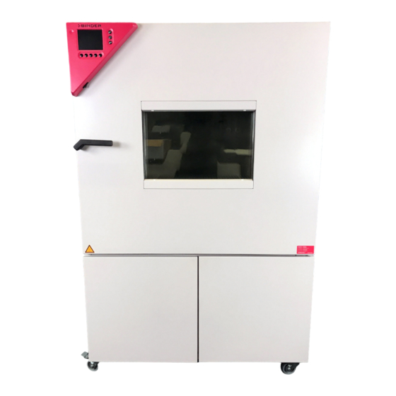
APT.line™ MKF (E3.1)
Environmental simulation chamber
for complex alternating climate profiles
with display program controller MB1
Model
MKF 115 (E3.1)
MKF 240 (E3.1)
MKF 720 (E3.1)
APT.line™ MKFT (E3.1)
Environmental simulation chamber
for complex alternating climate profiles with low temperature area
with display program controller MB1
Model
MKFT 115 (E3.1)
MKFT 240 (E3.1)
MKFT 720 (E3.1)
BINDER GmbH
Address
Tel.
Fax
Internet
E-mail
Service Hotline
Service Fax
Service E-Mail
Service Hotline USA
Service Hotline Asia Pacific
Service Hotline Russia and CIS +7 495 98815 17
Issue 04/2013
Art. No.
9020-0107, 9120-0107
9020-0183, 9120-0183
9020-0198, 9120-0198
Art. No.
9020-0152, 9120-0152
9020-0080, 9120-0080
9020-0083, 9120-0083
Post office box 102
D-78502 Tuttlingen
+49 7462 2005 0
+49 7462 2005 100
http://www.binder-world.com
info@binder-world.com
+49 7462 2005 555
+49 7462 2005 93 555
service@binder-world.com
+1 866 885 9794 or +1 631 224 4340 x3
+852 39070500 or +852 39070503
Art. No. 7001-0219
Advertisement
Table of Contents


Need help?
Do you have a question about the MKF 115 and is the answer not in the manual?
Questions and answers