Table of Contents
Advertisement
Operating Manual
Translation of the original operating manual
KBW (E6)
Growth chambers with light
with program control and adjustable light cassettes
Model
Model version
KBW 240
KBW240-230V
KBW 400
KBW400-230V
KBW 720
KBW720-230V
BINDER GmbH
Address: Post office box 102, 78502 Tuttlingen, Germany Phone: +49 7462 2005 0
Fax: +49 7462 2005 100 Internet: http://www.binder-world.com
E-mail: info@binder-world.com Service Hotline: +49 7462 2005 555
Service Fax: +49 7462 2005 93 555 Service E-Mail: service@binder-world.com
Service Hotline USA: +1 866 885 9794 or +1 631 224 4340 x3
Service Hotline Asia Pacific: +852 390 705 04 or +852 390 705 03
Service Hotline Russia and CIS: +7 495 988 15 16
Issue 11/2016
Art. No.
9020-0338, 9120-0338
9020-0339, 9120-0339
9020-0340, 9120-0340
Art. N0. 7001-0338
Advertisement
Table of Contents

Subscribe to Our Youtube Channel
Related Manuals for Binder KBW 240


Summary of Contents for Binder KBW 240
-
Page 1: Operating Manual
Fax: +49 7462 2005 100 Internet: http://www.binder-world.com E-mail: info@binder-world.com Service Hotline: +49 7462 2005 555 Service Fax: +49 7462 2005 93 555 Service E-Mail: service@binder-world.com Service Hotline USA: +1 866 885 9794 or +1 631 224 4340 x3 ... -
Page 2: Table Of Contents
Content SAFETY ........................6 Legal considerations ........................... 6 Structure of the safety instructions ...................... 6 1.2.1 Signal word panel ........................6 1.2.2 Safety alert symbol ........................7 1.2.3 Pictograms ..........................7 1.2.4 Word message panel structure ....................8 Localization / position of safety labels on the chamber ............... 8 Type plate ............................ - Page 3 TIMER PROGRAM: STOPWATCH FUNCTION ........... 40 Starting a timer program ........................40 8.1.1 Performance during program delay time ................. 41 Stopping a running timer program ..................... 41 8.2.1 Pausing a running timer program .................... 41 8.2.2 Cancelling a running timer program ..................42 Performance after the end of the program ..................
- Page 4 12. TEMPERATURE SAFETY DEVICES ..............73 12.1 Over temperature protective device (class 1) ................... 73 12.2 Overtemperature safety controller class 3.1 ..................73 12.2.1 Safety controller modes ......................73 12.2.2 Setting the safety controller ..................... 74 12.2.3 Message and measures in the state of alarm ................. 75 12.2.4 Function check ........................
- Page 5 19.5 Zero-voltage relay alarm outputs for temperature (option) .............. 115 19.6 Water protected internal socket (option) ..................116 19.7 Additional flexible Pt 100 temperature sensor (available via BINDER INDIVIDUAL customized solutions) ............................117 19.8 Object temperature display with flexible Pt 100 temperature sensor (option) ......... 117 20.
-
Page 6: Safety
Understanding and observing the instructions in this operating manual are prerequisites for hazard-free use and safety during operation and maintenance. In no event shall BINDER be held liable for any dam- ages, direct or incidental arising out of or related to the use of this manual. -
Page 7: Safety Alert Symbol
WARNING Indicates a potentially hazardous situation which, if not avoided, could result in death or serious (irreversible) injury. CAUTION Indicates a potentially hazardous situation which, if not avoided, may result in moderate or minor (reversible) injury. CAUTION Indicates a potentially hazardous situation which, if not avoided, may result in damage to the product and/or its functions or of a property in its proximity. -
Page 8: Word Message Panel Structure
Pictograms (warning signs) Hot surface (inner glass door above the glass door handle) Service label Keep safety labels complete and legible. Replace safety labels that are no longer legible. Contact BINDER Service for these replacements. KBW (E6) 11/2016 page 8/147... -
Page 9: Type Plate
KBW 240 Serial No. 00000000000000 Im Mittleren Ösch 5 Made in Germany 78532 Tuttlingen / Germany www.binder-world.com Figure 1: Type plate (example KBW 240 regular chamber) Indications of the type plate (example) Information BINDER Manufacturer: BINDER GmbH KBW 240 Model designation... -
Page 10: General Safety Instructions On Installing And Operating The Chambers
213-850 on safe working in laboratories (formerly BGI/GUV-I 850-0, BGR/GUV-R 120 or ZH 1/119, issued by the employers’ liability insurance association) (for Germany. BINDER GmbH is only responsible for the safety features of the chamber provided skilled electricians or qualified personnel authorized by BINDER perform all maintenance and repair, and if components relating to chamber safety are replaced in the event of failure with original spare parts. - Page 11 DANGER Electrical hazard. Danger of death. ∅ The chamber must NOT become wet during operation or maintenance. The chambers were produced in accordance with VDE regulations and were routinely tested in accord- ance to VDE 0411-1 (IEC 61010-1). During and shortly after operation, the temperature of the inner surfaces almost equals the set-point. CAUTION The glass doors, the glass door handles, the inner chamber, and the light cassettes will become hot during operation.
-
Page 12: Intended Use
Any corrosive damage caused by such ingredients is excluded from liability by BINDER GmbH. WARNING: If customer should use a BINDER chamber running in non-supervised continuous operation, we strongly recommend in case of inclusion of irrecoverable specimen or samples to split such specimen or samples and store them in at least two chambers, if this is feasible. -
Page 13: Measures To Prevent Accidents
Measures to prevent accidents The operator of the chamber must observe the following rule: “Betreiben von Arbeitsmitteln. Betreiben von Kälteanlagen, Wärmepumpen und Kühleinrichtungen“ (Operation of work equipment. Operation of refrig- eration systems, heat pumps and refrigeration equipment) (GUV-R 500 chap. 2.35) (for Germany). The manufacturer took the following measures to prevent ignition and explosions: •... -
Page 14: Chamber Description And Overview
APT-COM™ 3 DataControlSystem (option, chap. 19.1). The chamber comes equipped with an Ethernet serial interface for computer communication. In addition, the BINDER communication software APT-COM™ 3 permits networking up to 30 chambers and connecting them to a PC for controlling and programming, as well as recording and representing temperature data. -
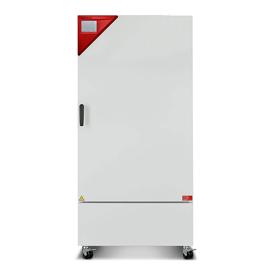
Page 15: Chamber Overview
Chamber overview Figure 2: Growth chamber with light KBW 240 Instrument box Door handle Outer door Refrigerating machine 2.3 Instrument panel 5,7" controller display with touchscreen USB interface Pilot lamp Figure 3: Instrument panel with MB2 program controller and USB interface... -
Page 16: Lateral Control Panels
Figure 4: Lateral control panels at the sides of the refrigerating module with optional equipment Main power switch DIN socket for additional Pt 100 sensor (may be available via BINDER INDIVIDUAL customized solutions) DIN socket for analog outputs (option) RS485 interface... -
Page 17: Completeness Of Delivery, Transportation, Storage, And Installation
Note on second-hand chambers (Ex-Demo-Units): Second-hand chambers are chambers that were used for a short time for tests or exhibitions. They are thoroughly tested before resale. BINDER ensures that the chamber is technically sound and will work flawlessly. Second-hand chambers are marked with a sticker on the chamber door. Please remove the sticker before commissioning the chamber. -
Page 18: Guidelines For Safe Lifting And Transportation
∅ Do NOT set the fork lifter from the chamber side. • Permissible ambient temperature range during transport: -10 °C / 14°F to +60 °C / 140°F You can order transport packing for moving or shipping purposes from BINDER service. 3.3 Storage Intermediate storage of the chamber is possible in a closed and dry room. - Page 19 • Permissible ambient temperature range during operation: +18 °C / 64.4 °F to +32 °C / 89.6 °F. At ele- vated ambient temperature values, fluctuations in temperature can occur. The ambient temperature should not be substantially higher than the indicated ambient tem- perature of +22 °C +/- 3 °C / 71.6 °F ±...
-
Page 20: Installation And Connections
Installation and connections Spacer for wall distance Please fix both spacers with the supplied screws at the chamber rear. This serves to ensure the pre- scribed minimum distance to the rear wall of 100 mm / 3.94 in. Figure 5: Spacer for wall distance Figure 6: Chamber rear with mounted spacers KBW (E6) 11/2016 page 20/147... -
Page 21: Mounting The Flexible Tilt Protection Kit (Kbw 400)
Mounting the flexible tilt protection kit (KBW 400) KBW size 400 liters should be equipped with the supplied flexible tilt protection kit in addition to the spac- ers for wall distance (chap. 4.1). Scope of delivery: • 4 Torx screws (spare parts) •... -
Page 22: Installation And Connection Of The Light Cassettes
Installation and connection of the light cassettes You can insert the light cassettes in different heights onto the beads at the lateral walls of the chamber. Insert and pull out the light cassettes only by the handles. Connect the cables of the light cas- settes to its closest connection socket at the right side in the back of the cham- ber. -
Page 23: Electrical Connection
1800 mm / 70.87 in in length. Voltage +/-10% at the indicated Current Chamber Model version Power plug power frequency type fuse KBW 240 shock-proof plug 200-230 V at 50 Hz 16 A 200-230 V at 50 Hz KBW 400 shock-proof plug 16 A KBW 720 200-230 V at 60 Hz •... -
Page 24: Functional Overview Of The Mb2 Chamber Controller
(trace file) and the graphical display of the measuring values in the in der chart recorder view. The MB2 program controller permits programming temperature cycles. You can enter values or programs directly at the controller or use the APT-COM™ 3 DataControlSystem software (option) specially developed by BINDER. Operating mode Temperature values... -
Page 25: Operating Functions In Normal Display
Operating functions in normal display Current operating mode Text list for information icons Date, time, authorization level of the logged-in user, memory Quick setpoint entry Continue to next screen Back to Normal display Information Program start Setpoint entry Event list Display of active alarms Access to main menu Figure 10: Operating functions of the MB2 controller in normal display (example values) -
Page 26: Display Views: Normal Display, Program Display, Chart-Recorder Display
Display views: Normal display, program display, chart-recorder display Press the Change view icon to toggle between normal display, program display and chart- recorder display. Press the Normal display icon to return from program display and chart recorder display back to Normal display. -
Page 27: Controller Icons Overview
Controller icons overview Navigation icons in Normal display Icon Signification Function Main menu Access from Normal display to the main menu Alarm Access from Normal display to the list of active alarms Event list Access from Normal display to the event list Access from Normal display to the setpoint entry menu: setpoint Setpoint setting entry for Fixed value operation, safety controller settings... - Page 28 Information icons Icon Signification Information Idle mode Controller in Idle mode Temperature range Current actual temperature value outside the tolerance range Door open Chamber door is open Light level 1 (40% illumination) turned on (operation line “Light Light level 1 level 1”...
-
Page 29: Operating Modes
Operating modes The MB2 program controller operates in the following operating modes: • Idle mode The controller is not functional, i.e., there is no heating or refrigeration. The fan is off. The chamber approximates ambient values. The fluorescent tubes are off. You can activate and deactivate this operating mode with the “Idle mode”... -
Page 30: Controller Menu Structure
Controller menu structure Use the navigation icons in the screen footer in Normal display to access the desired controller func- tions. Normal display The available functions depend on the current authorization level “Service”, “Admin” or “User” (chap. 13.1). This is selected either during login or can be available without password protection. Main menu: program settings, further information, “Service”... -
Page 31: Main Menu
• Access to service data, controller reset to factory settings (chap. 5.5.3) • Available only for users with “Service” and “Admin” authorization level. Full functional range only for BINDER Service (users with “Service” authorization level). “Programs” submenu • Access to the controller’s program functions (chap. 8, 9, 10) -
Page 32: Settings" Submenu
5.5.3 “Service” submenu The “Service” submenu is available for users with “Service” or “Admin” authorization level. When logged-in with “Admin” authorization level the user will find information to tell the BINDER Service in service case. Path: Main menu > Service Serial number of the chamber, setup version chap. -
Page 33: Principle Of Controller Entries
Principle of controller entries In the selection and entry menus there are icons displayed in the footers which you can use to take over the entry or cancel it. Selection menu (example) Entry menu (example) There are the following possibilities: Press the Confirm icon to take over the entries and exit the menu or continue the menu se- quence. -
Page 34: Performance When Opening The Door
To reduce odors quickly we recommend heating up the chamber to its nominal temperature for one day and in a well-ventilated location. WARNING: If customer should use a BINDER chamber running in non-supervised continuous operation, we strongly recommend in case of inclusion of irrecoverable specimen or samples to split such specimen or samples and store them in at least two chambers, if this is feasible. -
Page 35: Controller Settings Upon Start Up
Controller settings upon start up The window „Language selection“ enables the language selection, in case that it’s activated in the “Start- up” menu. Afterwards occurs a request of the time zone and the temperature unit. The controller will function in the operating mode, which was active before the last shut-down. It controls temperature in fixed value operating mode to the last entered value and in the program mode to the set point achieved beforehand. -
Page 36: Set-Point Entry In "Fixed Value" Operating Mode
Set-point entry in “Fixed value” operating mode In Fixed value operating mode you can enter a temperature set-point, the fan speed, and the switching- state of up to 16 operation lines. All settings made in Fixed value operating mode remain valid until the next manual change. They are saved also when turning off the chamber or in case of toggling to Idle Mode or Program Mode. -
Page 37: Set-Point Entry Through The "Setpoints" Menu
Set-point entry through the “Setpoints” menu Press the Setpoint setting icon to access the “Setpoint” setting menu from Normal display. Press the Back icon to go return to Normal display from any menu. “Setpoints” menu. Select the parameter to enter the setpoint. Select “Fixed value operation setpoints”. -
Page 38: Direct Setpoint Entry Via Normal Display
Direct setpoint entry via Normal display Alternatively you can also enter the setpoints directly via Normal display. Normal display. Example: “Temperature” entry menu. Select the setpoint you want to change. Enter the desired value and press the Confirm icon. Automatic correction of the actual value when turning on or off the illumi- nation The chambers have been adjusted for operation with maximum illumination. -
Page 39: Light Commutation And Special Controller Functions Via Operation Lines
Light commutation and special controller functions via operation lines You can define the switching state of up to 16 operation lines (control contacts). They are used to activate / deactivate special controller functions. • Operation line “Idle mode” activates / deactivates the operating mode “Idle mode” (chap. 5.4). •... -
Page 40: Timer Program: Stopwatch Function
Timer program: stopwatch function During an entered duration the controller constantly equilibrates to the setpoints entered in Fixed value operation mode (temperature, fan speed, configuration of the operation lines). This duration can be en- tered as a “Timer program”. During the program runtime, any setpoint changes do not become effective; the controller equilibrates to the values which were active during program start. -
Page 41: Performance During Program Delay Time
“Program start” menu. Enter the desired start time of the program and press the Confirm icon. The program delay Select the field “Program start”. time until program start begins. Normal display. Information on the bottom of the screen indicates the currently running program and the time already passed. -
Page 42: Cancelling A Running Timer Program
8.2.2 Cancelling a running timer program Press the Program cancelling icon to cancel the program. A confirmation prompt is displayed. Press the Confirm icon to confirm that the program shall really be can- celled. After confirming the message the controller changes to Fixed value operation mode. The setpoints of Fixed value operation mode will then equilibrate. -
Page 43: Time Programs
Time programs The MB2 program controller permits programming time programs with real-time reference. It offers 25 program memory positions with up to 100 program sections each. For each program section you can enter a temperature set-point, fan speed, section duration, type of tem- perature transition (ramp or step) and the tolerance range. -
Page 44: Performance During Program Delay Time
“Program start” menu. “Program start” menu. Select the field “Program start”. Enter the desired program start time and press the Confirm icon. The program delay time until program start begins. The program end is adapted automatically de- pending on the entered program duration. When all settings have been completed, press Normal display. -
Page 45: Stopping A Running Time Program
Stopping a running time program 9.2.1 Pausing a running time program Press the Program pause icon to interrupt the program.. The program is paused. The program runtime stops running down, the time display flashes. There are the following options: Press the Program start icon to continue the program Press the Cancelling icon to cancel the program 9.2.2 Cancelling a running time program Press the Program cancelling icon to cancel the program. -
Page 46: Creating A New Time Program
Creating a new time program Path: Main menu > Programs > Time program “Time program” menu: Enter the program name and, if desired, addi- overview of the existing programs. tional program information in the corresponding fields. Select an empty program place. Press the Confirm icon. - Page 47 Program editor: “Edit program” menu Select the desired function and press the Confirm icon. The program editor offers following options: • Change the program name • Copy program • Replace program: Replacing an new or an existing program with the copied program. This menu point is visible only after a program has been copied.
-
Page 48: Section Editor: Section Management
Section editor: Section management Path: Main menu > Programs > Time program Select the desired program. Program view. Section view (example: section 1). Select the desired program section There are the following options: (example: section 1) Select a parameter to enter or modify the according value (chap. -
Page 49: Add A New Section
9.6.1 Add a new section Section editor: “Edit section” menu. Select “Add new section” and press the Confirm icon. Then select whether to insert the new section before or after the current section. Press the Confirm icon. The new section opens. 9.6.2 Copy and insert or replace a section Program view. - Page 50 Section editor: “Edit section” menu Section view (example: section 1). Select “Copy section” and press the Confirm Press the Close icon to change to the program icon. view, if you want to select another section to be replaced or before or after which the copied The current section (example: section 1) is section shall be inserted copied.
-
Page 51: Deleting A Section
Select “Replace section” to replace the selected sec- tion with the copied section Select “Insert section” to additionally add the copied section. In this case select whether to insert it before or after the selected section. Section editor: “Edit section” menu Press the Confirm icon 9.6.3 Deleting a section In the program view select the program section to be deleted. -
Page 52: Section Duration
9.7.1 Section duration Section view (partial view). Select the field “Duration” indicating the time. “Duration” entry menu. Enter the desired section duration with the arrow keys and press the Confirm icon. Setting range: 0 up to 99 hours 59 min 59 sec. 9.7.2 Set-point ramp and set-point step You can define the type of temperature transitions for each individual program section. - Page 53 Programming in the “step” mode allows only two kinds of temperature transitions: • Programming gradual changes of temperature (ramps) is impossible in the “step” mode • Program sections with constant temperature The setpoints (target values) of two subsequent program sections are identical; so the temperature remain constant during the entire duration of the first program section.
-
Page 54: Light Commutation And Special Controller Functions Via Operation Lines
9.7.3 Light commutation and special controller functions via operation lines You can define the switching state of up to 16 operation lines (control contacts). They are used to activate / deactivate special controller functions. • Operation line “Idle mode” activates / deactivates the operating mode “Idle mode” (chap. 5.4). •... -
Page 55: Temperature Setpoint
9.7.4 Temperature setpoint Section view. “Temperature” entry menu. Select the field “Temperature”. Enter the desired temperature and press the Confirm icon. Setting range: -5 °C up to 70 °C The controller returns to the section view. Entering the set point values when operating without illumination: Adapt the setting of the temperature set-point according to the table in chap. -
Page 56: Tolerance Ranges
9.7.6 Tolerance ranges For temperature, you can specify a tolerance range for each program section with different values for the tolerance minimum and maximum. When the actual value exceeds the given threshold, the program is interrupted. This is indicated on the display (see below). When the actual temperature is situated again within the entered tolerance limits, the program automatically continues. -
Page 57: Repeating One Or Several Sections Within A Time Program
If one of those actual values for which a tolerance range has been specified lies outside this program tol- erance range the whole program course is interrupted. During this program interruption time the controller equilibrates to the set-points of the current section. The screen header indicates “Program pause (tolerance band)”. -
Page 58: Saving The Time Program
Section view. Entry menu „Start section for repetition“. Select the field “Start section for repetition”. Enter the section number, at which the repetition should start and press the Confirm icon. Setting range: 1 up to one section before the cur- rent selected section The controller returns to the section view. -
Page 59: Week Programs
Week programs The MB2 program controller permits programming week programs with real-time reference. It offers 5 week program places in total with up to 100 shift points for each week program. Path: Main menu > Programs> Week program 10.1 Starting an existing week program Normal display. -
Page 60: Cancelling A Running Week Program
After starting the week program, the previously entered week program setpoints are active and will be equilibrated according to the current time. Information on the bottom of the screen indicates the currently running program. 10.2 Cancelling a running week program Press the Program cancelling icon to cancel the program. -
Page 61: Creating A New Week Program
10.3 Creating a new week program Path: Main menu > Programs > Week program Enter the program name and, if desired, addi- “Week program” menu: tional program information in the corresponding overview of the existing programs. fields. Select an empty program place. Press the Confirm icon. -
Page 62: Program Editor: Program Management
10.4 Program editor: program management Path: Main menu > Programs > Week program Program view (example: program 1). “Week program” menu: overview of the existing programs. If a new program has been created, there is just one program section. Select an existing program (example: program There are the following options: ... -
Page 63: Section Editor: Section Management
To add a new section, select “Add new section” Program view. and press the Confirm icon. With a new section no weekday is specified. There- The program view opens. fore the section is first marked in red and cannot be saved. -
Page 64: Add A New Section
Section editor: “Edit section” menu Select the desired function and press the Confirm icon. The section editor offers following options: • Copy section • Replace section: Replacing an existing section with the copied section. This menu point is visible only after a section has been copied. -
Page 65: Copy And Insert Or Replace A Section
10.5.2 Copy and insert or replace a section Program view Section editor: “Edit section” menu Select the section to be replaced or before or Select “Copy section” and press the Confirm after which the copied section shall be inserted icon. (example: section 1). -
Page 66: Weekday
“Change program name” menu. In the field “Course” select the desired setting “Ramp” or “Step” and press the Confirm icon. 10.6.2 Weekday In the field “Weekday” select the desired weekday. With “Daily” selected, this section will run every day at the same time. -
Page 67: Temperature Setpoint
10.6.4 Temperature setpoint Section view. “Temperature” entry menu. Select the field “Temperature”. Enter the desired temperature and press the Confirm icon. Setting range: -5 °C up to 70 °C The controller returns to the section view. 10.6.5 Fan speed setpoint Section view. -
Page 68: Light Commutation And Special Controller Functions Via Operation Lines
10.6.6 Light commutation and special controller functions via operation lines You can define the switching state of up to 16 operation lines (control contacts). They are used to activate / deactivate special controller functions. • Operation line Idle mode” activates / deactivates the operating mode “Idle mode” (chap. 5.4). •... -
Page 69: Notification And Alarm Functions
Notification and alarm functions 11.1 Notification and alarm messages overview 11.1.1 Notifications Notifications are indicated by information icons displayed in the screen header in Normal display An information icon serves as an indication of a certain condition. If this condition persists, in some cases an alarm will be triggered after a fix or configurable interval. As long as the condition persists, the information icon therefore continues to be displayed also in state of alarm. -
Page 70: Alarm Messages
11.1.2 Alarm messages Start after Zero-voltage relay Condition Alarm message condition occurred alarm output (option) The current actual temperature value after configurable is outside the tolerance range (chap. time as alarm start Temperature range time 11.4) Chamber door open Door open after 5 minutes ---- Power failure... -
Page 71: Resetting An Alarm, List Of Active Alarms
11.3 Resetting an alarm, list of active alarms Normal display in state of alarm (example). List of active alarms. Press the Alarm icon Press the Reset alarm icon. Pressing the Reset alarm icon mutes the buzzer for all active alarms. The icon then disappears. •... -
Page 72: Activating / Deactivating The Audible Alarm (Alarm Buzzer)
Submenu “Various”. “Temperature range” entry menu. Select the field ”Temperature range”. Enter the desired value for the temperature range and press the Confirm icon. Setting range: 2 °C to 20 °C There are the following possibilities: Press the Confirm icon to take over the entries and exit the menu. Press the Close icon to exit the menu without taking over the entries. -
Page 73: Temperature Safety Devices
The user cannot restart the device again. The protective cut-off device is located internally. Only a service specialist can replace it. Therefore, please contact an authorized service provider or BINDER Service. 12.2 Overtemperature safety controller class 3.1 The chambers are regularly equipped with an electronic overtemperature safety controller (temperature safety device class 3.1 according to DIN 12880:2007). -
Page 74: Setting The Safety Controller
Example: Desired temperature value: 40 °C, desired safety controller value: 45 °C. Possible settings for this example: Temperature set point Safety controller mode Safety controller set-point Limit (absolute) 45 °C 40 °C Offset (relative) 5 °C 12.2.2 Setting the safety controller Press the Setpoint setting icon to access the “Setpoint”... -
Page 75: Message And Measures In The State Of Alarm
“Setpoints” menu. “Offset” entry menu. Select the corresponding field “Limit” or “Off- Enter the desired safety controller setpoint and set” (example: “Offset”) press the Confirm icon. Regularly check the safety controller setting for set-point type “Limit” or “Offset” • in Fixed value operating mode according to the entered set-point temperature value •... -
Page 76: Temperature Safety Device Class 3.3 (Option)
12.3 Temperature safety device class 3.3 (option) With the option over/under temperature protective device (temperature safety device class 3.3 acc. to DIN 12880:2007) the chamber is equipped with two additional safety devices (class 3.1 and class 3.2). The combination of the safety devices is regarded as a safety device class 3.3. The temperature safety device, class 3.3, serves to protect the chamber, its environment and the contents from exceeding the maximum permissible temperature. -
Page 77: Temperature Safety Device Class 3.1
12.3.1 Temperature safety device class 3.1 If you turn the control knob (8) to its end-stop (position 10), the safety device (8a) class 3.1 protects the appliance. If you set the temperature a little above the set-point, it protects the charging material. If the safety device class 3.1 has taken over control, identifiable by the red alarm lamp (8a) lighting up, the message “Temp. -
Page 78: Temperature Safety Device Class 3.2
12.3.2 Temperature safety device class 3.2 The safety device class 3.2 is equivalently set to a minimum temperature the (9a) chamber will not fall below. This protection against prohibited low tempera- tures can, for example, serve to protect sensitive cultures from cooling down too much. -
Page 79: User Management
• All passwords can be changed in the “log out” submenu (chap. 13.3). “Service” authorization level • Authorization level only for BINDER service • Extensive authorization for controller operation and configuration, access to service data • The passwords for “Service”, “Admin” and “User” authorization levels can be changed in the “log out”... - Page 80 Operation after user login At user login, the authorization level is selected and confirmed by entering the respective pass- word. Following user login, controller operation is avail- able, recognizable by the open-lock icon in the header. The available controller functions corre- spond to the user’s authorization level.
- Page 81 Information window To check the authorization level of the user currently logged-in, select in Normal display the arrow far right in the display header. The information window shows date and time, the controller’s free memory space and under “Authoriza- tion” the authorization level of the current user. If passwords have been assigned for all authorization levels, a user without login (password entry) has no authorization.
-
Page 82: Log In
13.2 Log in Path: Main menu > User > Log in Controller without a user logged-in Selection of user type (example) All selection possibilities are password protected Controller with logged-in user There are the following possibilities: Press the Confirm icon to take over the entries and exit the menu. Press the Close icon to exit the menu without taking over the entries. -
Page 83: Log Out
13.3 Log out Path: Main menu > User > Log out User logoff with “Admin” authorization Controller Controller with without a user logged-in user logged-in User logoff with “Admin” authorization Controller Controller with without a user logged-in user logged-in 13.4 User change If the password function has been deactivated (chap.13.5.2) this function is not available. -
Page 84: Password Assignment And Password Change
User selection (example) All selection possibilities are password protected Controller with logged- in user 13.5 Password assignment and password change This function is not available for a user logged-in with “User” authorization. 13.5.1 Password change A logged-in user can change the passwords of his current level and of the next lower level(s). Example: A user with “Admin”... - Page 85 Selection of the authorization level Enter desired password. (example: view with “Admin” authorization) If desired, press the Change keyboard icon to access other entry windows. In the “Keyboard switch” window you can select different keyboards to enter uppercase and lowercase letters, digits, and special characters.
- Page 86 Entry of digits Entry of special characters To confirm the password after the entry, repeat the entry and press the Confirm icon. KBW (E6) 11/2016 page 86/147...
-
Page 87: Deleting The Password For An Individual Authorization Level
13.5.2 Deleting the password for an individual authorization level A user logged-in with “Service” or “Admin” authorization can delete the passwords of his current level and of the next lower level(s). To do this no password is entered during a password change. Path: Main menu >... -
Page 88: New Password Assignment For "Service" Or "Admin" Authorization Level When The Password Function Was Deactivated
13.5.3 New password assignment for “service” or “admin” authorization level when the password function was deactivated If the password protection for an authorization level has been deactivated, i.e., no password is assigned, no login for this level is possible. Therefore access to this authorization level is available without login. If the password for the “Service”... -
Page 89: Activation Code
13.6 Activation code Certain functions of the controller can be unlocked with a previously generated activation code. The activation code enables access to functions available only in the “Service” authorization level by users without a “Service” authorization. Such functions include e.g., adjustment or extended configurations. The activation code is available in authorization levels. -
Page 90: General Controller Settings
General controller settings Most of the general settings can be accessed in the “Settings” submenu, which is available for users with “Service” or “Admin” authorization level. It serves to enter date and time, select the language for the con- troller menus and the desired temperature unit and to configure the controller’s communication functions. 14.1 Selecting the controller’s menu language The MB2 program controller communicates by a menu guide using real words in German, English, French, Spanish, and Italian. -
Page 91: Setting Date And Time
Change of the temperature unit between °C and °F. If the unit is changed, all values are converted accordingly C = degree Celsius 0 °C = 31°F Conversion: [value in °F] = [value in °C] ∗ 1,8 + 32 F= degree Fahrenheit 100 °C = 212°F 14.3 Setting date and time Following start-up of the chamber after language selection:... - Page 92 “Date and time” submenu. “Date and time” submenu. In the field “Daylight saving time switch” select Select the desired time zone and press the the desired setting “Automatic” or “Inactive”. Confirm icon. “Date and time” submenu. “Date and time” submenu. Select the desired start of the daylight saving Select the desired end of the daylight saving time.
-
Page 93: Display Configuration
14.4 Display configuration 14.4.1 Adapting the display parameters This function serves to configure parameters like display brightness and operating times. Path: Main menu > Settings > Display > Display “Display” submenu. Move the grey slide to the left or right to define the brightness of the display Select the field “Brightness”. - Page 94 “Display” submenu. In the field “Activate continuous operation” select the desired setting “Yes” or “No”. “Display” submenu. Entry menu “Begin continuous operation”. Select the field “Begin continuous operation” Enter the time with the arrow keys and press the (possible only if continuous operation is activat- Confirm icon.
-
Page 95: Touchscreen Calibration
14.4.2 Touchscreen calibration This function serves to optimize the display for the user’s individual angular perspective. Path: Main menu > Calibrate touchscreen Normal display. Follow the instructions on the display. You need to touch all four corners of the touchscreen to calibrate it. Appropriate boxes appear succes- sively in each corner. -
Page 96: Network And Communication
This menu allows to configure the communication parameters of the RS485 interface. The device address is required to recognize chambers with this interface type in a network, e.g. when connecting it to the optional communication software BINDER APT-COM™ 3 DataControlSystem (chap. 19.1). In this case do not change the other parameters. -
Page 97: Ethernet
“Serial interfaces” submenu. “Device adress” entry menu Select the field “Device address”. Enter the device adress and press the Con- firm icon. Factory setting: “1”. 14.5.2 Ethernet 14.5.2.1 Configuration Path: Main menu > Settings > Ethernet “Ethernet” submenu. In the field “IP address assignment” select the desired setting “Automatic (DHCP)“... -
Page 98: Web Server
This controller menu serves to configure the web server. Then you can enter the chamber’s IP-address in the Internet. The IP address is available via Chamber information > Ethernet. The BINDER web server opens. Enter the user name and password which have been assigned for the web server in the controller menu. - Page 99 Submenu “Web server”. “User name” entry menu. Select the field “User name”. Enter the desired user name and press the Confirm icon. Submenu “Web server”. “Password” entry menu (example). Select the field “Password”. Enter the desired password and press the Con- firm icon.
-
Page 100: E-Mail
14.5.4 E-Mail As soon as an alarm was triggered, an e-mail is sent to the configured e-mail address. Path: Main menu > Settings > Email “Email” submenu. “Email address” entry menu. Select the field of the e-mail address to be Enter the e-mail address. - Page 101 Select the field “SMTP mail server URL”. Enter the SMPT mail server URL and press the Confirm icon. Select the field “Email sender”. Enter the desired Email sender and press the Confirm icon. There are the following possibilities: Press the Confirm icon to take over the entries and exit the menu. Press the Close icon to exit the menu without taking over the entries.
-
Page 102: Usb Menu
14.6 USB menu When you insert a USB-stick, the “USB” menu opens. Depending on the user’s authorization level, different functions (highlighted in black) are available for the logged-in user. Available functions with “User” authorization level Available functions with “Admin” authorization level Available functions with “Service”... -
Page 103: General Information
General information 15.1 Service contact page Path: Main menu > Contact 15.2 Current operating parameters Normal display. “Info” menu. Press the Information icon. Select the desired information. Selection “Setpoints“. Information on the entered setpoints and opera- tion lines. Selection “Program operation”. Information on a currently running program. -
Page 104: Event List
Selection “Actual values”. Selection “Safety controller”. Information on the current actual values. Information on the safety controller. 15.3 Event list Press the Event list icon to access the event list from Normal display. Press the Back icon to return from every setting menu to Normal display. Press the Update icon to update the event list. -
Page 105: Technical Chamber Information
15.4 Technical chamber information Path: Main menu > Device info Chamber name and setup Versions of CPU, I/O module and safety con- for BINDER troller Service Information on digital and analog inputs and for BINDER outputs and phase angle outputs... -
Page 106: Chart Recorder Display
Chart recorder display This view offers graphic representation of the measurement course. Data representation imitates a chart recorder and allows recalling any set of measured data at any point of time taken from the recorded peri- 16.1 Views Press the Change view icon to access the pen recorder display. Show and hide legend: Legend displayed on the right side of the display... - Page 107 History display The pen recorder is paused. Data recording continues in the background. Move the central red line by tapping and holding to the desired position. The legend at the right side shows the values of the current line position. Change to history display Then further icons appear: History display: Curve selection...
-
Page 108: Setting The Parameters
History display: Zoom function “Zoom” submenu. Select the zoom factor and press the Confirm icon Select the zoom factor History display: Show and hide arrow keys “Page selection” submenu. Arrow keys are shown on the left and on the right. Use them to move along the timeline. - Page 109 “Measurement chart” submenu. “Measurement chart” submenu. For scaling the representation select the desired In the field “Storage values” select the desired temperature value. value type to be displayed. Temperature display range: -20 °C up to 110 °C Example: “Min. temperature” entry menu. Enter the desired value and press the Confirm icon.
-
Page 110: Defrosting At Refrigerating Operation
Defrosting at refrigerating operation BINDER growth chambers with light are very diffusion-proof. To ensure high temperature precision there is no automatic cyclic defrosting device. The DCT™ refrigerating system largely avoids icing of the evapo- ration plates. However, at very low temperatures the moisture in the air can condense on the evaporator plates leading to icing. -
Page 111: Illumination System
Type of fluorescent tube: T8 fluorescent tube in form of a rod with a tube diameter of 26 mm / 1.02 in. Length according to chamber size: 600 mm / 23.6 in (KBW 240, 400), or 900 mm / 35.4 in (KBW 720). - Page 112 Figure 16: Positions of light cassettes KBW 720 This position is only meant for the light cassettes. Due to their connections, shelves cannot be positioned here. You can move the light cassettes to the indicated positions. Plug rear front Figure 17: Arrangement of the fluorescent tubes in the light cassette You will obtain optimum homogeneity by alternately placing the fluorescent tubes of the same type, i.e., opposite arrangement of the inscription: Inscription...
-
Page 113: Illumination Control
Operation with light cassettes and illumination on: Maximum temperature 60 °C / 140 °F. Operation with light cassettes and illumination off: Do also NOT operate the chamber at tem- peratures >60 °C / 140 °F. Otherwise, the lifetime of the fluorescent tubes will be considerably reduced. -
Page 114: Options
The BINDER Data Logger is equipped with a keyboard and a large LCD display, alarm functions and a real-time function. Measurement data are recorded in the Data Logger and can be read out after the measurement via the RS232 interface of the Data Logger. -
Page 115: Analog Outputs For Temperature (Option)
19.4 Analog outputs for temperature (option) With this option the chamber is equipped with analog outputs 4-20 mA for temperature. These outputs allow transmitting data to external data registration systems or devices. The connection is realized as a DIN socket (3) in the right lateral control panel as follows: ANALOG OUTPUT 4-20 mA DC PIN 1: Temperature –... -
Page 116: Water Protected Internal Socket (Option)
In case of power failure, transmission of the alarm via zero-voltage relay outputs remains active for the duration of the power failure. Afterwards, both contacts will close automatically. When using the communication software APT-COM™ 3 DataControlSystem (option, chap. 19.1) via the Ethernet interface of the chamber for data acquisition, the alarm is not automati- cally transmitted to the APT-COM™... -
Page 117: Additional Flexible Pt 100 Temperature Sensor (Available Via Binder Individual Customized Solutions)
(sample values) The object temperature data are put out together with the data of the temperature controller and can be documented by the communication software APT-COM™ (option, chap. 19.1) developed by BINDER. Technical data of the Pt100 sensor: • Three-wire technique •... -
Page 118: Maintenance, Cleaning, And Service
With an increased amount of dust in the ambient air, clean the condenser fan (by suction or blowing) sev- eral times a year. We recommend taking out a maintenance agreement. Please consult BINDER Service: BINDER telephone hotline: +49 (0) 7462 2005 555... -
Page 119: Replacement Of The Fluorescent Tubes
20.2 Replacement of the fluorescent tubes The average life expectancy of the fluorescent tubes is about 10,000 hours. We recommend replacing the tubes every year in order to ensure full light intensity. To replace the fluorescent tubes, unscrew and remove the clamping strips resting against the glass plate (Allen screwdriver). -
Page 120: Cleaning
Do not use cleaning agents that may cause a hazard due to reaction with components of the device or the charging material. If there is doubt regarding the suitability of cleaning products, please contact BINDER service. We recommend using the neutral cleaning agent Art. No. 1002-0016 for a thorough cleaning. -
Page 121: Decontamination
For chemical disinfection, we recommend using the disinfectant spray Art. No. 1002-0022. Any corrosive damage that may arise following use of other disinfectants is excluded from liability by BINDER GmbH. With every decontamination method, always use adequate personal safety controls. -
Page 122: Sending The Chamber Back To Binder Gmbh
20.4 Sending the chamber back to BINDER GmbH If you return a BINDER product to us for repair or any other reason, we will only accept the product upon presentation of an authorization number (RMA number) that has previously been issued to you. An au- thorization number will be issued after receiving your complaint either in writing or by telephone prior to your sending the BINDER product back to us. -
Page 123: Disposal
(Elektro- und Elektronikgerätegesetz, ElektroG from 20 Octo- ber 2015, BGBl. I p. 1739) or contact BINDER service who will organize taking back and disposal of the chamber according to the German national law for electrical and electronic equipment (Elektro- und El- ektronikgerätegesetz, ElektroG from 20 October 2015, BGBl. - Page 124 Elektronikgerätegesetz, ElektroG from 20 October 2015, BGBl. I p. 1739). Instruct BINDER Service to dispose of the device. The general terms of payment and delivery of BINDER GmbH apply, which were valid at the time of purchasing the cham- ber.
-
Page 125: Disposal Of The Chamber In The Member States Of The Eu Except For The Federal Republic Of Germany
According to Annex I of Directive 2012/19/EU of the European Parliament and of the Council on waste electrical and electronic equipment (WEEE), BINDER devices are classified as “monitoring and control instruments” (category 9) only intended for professional use“. They must not be disposed of at public col- lecting points. -
Page 126: Disposal Of The Chamber In Non-Member States Of The Eu
21.5 Disposal of the chamber in non-member states of the EU CAUTION Alteration of the environment. For final decommissioning and disposal of the chamber, please contact BINDER ser- vice. Follow the statutory regulations for appropriate, environmentally friendly disposal. -
Page 127: Troubleshooting
(chap. 4.4). Check chamber fuse and replace Chamber fuse has responded. it if appropriate. If it responds Chamber without function. again, contact BINDER service. Controller defective. Nominal temperature exceeded Contact BINDER service. by 10° due to chamber failure. Over temperature protective de- vice (class 1) responds. - Page 128 - - - - or <-<-< or >->-> Short-circuit. Miscellaneous Fluorescent tube does not illumi- Defective fluorescent tube. Replace the fluorescent tubes. nate. Only qualified service personnel authorized by BINDER must perform repair. Repaired chambers must comply with the BINDER quality standards. KBW (E6) 11/2016 page 128/147...
-
Page 129: Technical Description
December 1996 by TÜV CERT). All test equipment used is subject to the administration of measurement and test equipment that is also a constituent part of the BINDER QM DIN EN ISO 9001 systems. They are controlled and calibrated to a DKD-Standard at regular intervals. -
Page 130: Technical Data
23.4 Technical Data Chamber size Exterior dimensions Width, net mm / inch 925 / 36.42 925 / 36.42 1250 / 49.21 Height, gross (incl. castors) mm / inch 1460 / 57.48 1945 / 76.57 1925 / 75.79 Depth, net mm / inch 800 / 31.50 800 / 31.50 890 / 35.04... - Page 131 +22 °C +/- 3°C / 71.6 °F +/- 5.4 °F and a power supply voltage fluctuation of +/-10%. Technical data is determined in accordance to BINDER factory standard Part 2:2015 and DIN 12880:2007. All indications are average values, typical for chambers produced in series. We reserve the right to change technical specifications at any time.
-
Page 132: Equipment And Options (Extract)
23.5 Equipment and options (extract) To operate the chamber, use only original BINDER accessories or accessories / components from third-party suppliers authorized by BINDER. The user is responsible for any risk arising from using unauthorized accessories. Regular equipment Microprocessor display program controller with digital display and touchscreen Ethernet interface for computer communication Temperature safety device class 3.1 acc. -
Page 133: Spare Parts And Accessories (Extract)
23.6 Spare parts and accessories (extract) BINDER GmbH is responsible for the safety features of the chamber only, provided skilled electricians or qualified personnel authorized by BINDER perform all maintenance and repair, and if components relating to chamber safety are replaced in the event of failure with original spare parts. -
Page 134: Dimensions Kbw 240
23.7 Dimensions KBW 240 KBW (E6) 11/2016 page 134/147... -
Page 135: Dimensions Kbw 400
23.8 Dimensions KBW 400 KBW (E6) 11/2016 page 135/147... -
Page 136: Dimensions Kbw 720
23.9 Dimensions KBW 720 KBW (E6) 11/2016 page 136/147... -
Page 137: Certificates And Declarations Of Conformity
Certificates and declarations of conformity 24.1 EU Declaration of Conformity KBW (E6) 11/2016 page 137/147... - Page 138 KBW (E6) 11/2016 page 138/147...
-
Page 139: Certificate For The Gs Mark Of Conformity Of The "Deutsche Gesetzliche Unfallversicherung E.v." (German Social Accident Insurance) Dguv
24.2 Certificate for the GS mark of conformity of the “Deutsche Gesetzliche Unfallversicherung e.V.“ (German Social Accident Insurance) DGUV KBW (E6) 11/2016 page 139/147... - Page 140 KBW (E6) 11/2016 page 140/147...
-
Page 141: Product Registration
Product registration KBW (E6) 11/2016 page 141/147... -
Page 142: Contamination Clearance Certificate
Contamination clearance certificate 26.1 For chambers located outside USA and Canada Declaration regarding safety and health Erklärung zur Sicherheit und gesundheitlichen Unbedenklichkeit The German Ordinance on Hazardous Substances (GefStofV), and the regulations regarding safety at the workplace, require that this form be filled out for all products that are returned to us, so that the safety and the health of our employees can be guaranteed Die Sicherheit und Gesundheit unserer Mitarbeiter, die Gefahrstoffverordnung GefStofV und die Vorschriften zur Sicherheit am Arbeitsplatz machen es erforderlich, dass dieses Formblatt für alle Produkte, die an uns zurückge-... - Page 143 Kind of transport / transporter / Transportweg/Spediteur: Transport by (means and name of transport company, etc.) Versendung durch (Name Spediteur o.ä.) ___________________________________________________________________________________ Date of dispatch to BINDER GmbH / Tag der Absendung an BINDER GmbH ___________________________________________________________________________________ KBW (E6) 11/2016 page 143/147...
- Page 144 We are aware that, in accordance with Article 823 of the German Civil Code (BGB), we are directly liable with regard to third parties, in this instance especially the employees of BINDER GmbH, who have been entrusted with the handling / repair of the unit / component. / Es ist uns bekannt, dass wir gegenüber Dritten –...
-
Page 145: For Chambers Located In Usa And Canada
After we have received and reviewed the complete information we will decide on the issue of a RMA num- ber. Please be aware that size specifications, voltage specifications as well as performance specifications are available on the internet at www.binder-world.us at any time. Take notice of shipping laws and regulations. - Page 146 Customer (End User) Decontamination Declaration Health and Hazard Safety declaration To protect the health of our employees and the safety at the workplace, we require that this form is com- pleted by the user for all products and parts that are returned to us. (Distributors or Service Organizations cannot sign this form) NO RMA number will be issued without a completed form.
- Page 147 4.5 Shipping laws and regulations have not been violated. I hereby commit and guarantee that we will indemnify BINDER Inc. for all damages that are a con- sequence of incomplete or incorrect information provided by us, and that we will indemnify and hold harmless BINDER Inc.
Need help?
Do you have a question about the KBW 240 and is the answer not in the manual?
Questions and answers