Binder KBF P 240 Translation Of Original Operation Manual
Constant climate chambers with program control
and adjustable light cassettes; constant climate chambers
with ich compliant illumination and light dose detection
with program control and adjustable light cassettes; growth chambers with light and humidi
Table of Contents
Advertisement
Quick Links
Operating Manual
Translation of the original operating manual
KBF P (E6)
Constant climate chambers with program control
and adjustable light cassettes
Model
Model version
KBF P 240
KBFP240-230V
KBF P 240-UL
KBFP240UL-240V
KBF P 720
KBFP720-230V
KBF P 720-UL
KBFP720UL-240V
KBF LQC (E6)
Constant climate chambers
with ICH compliant illumination and light dose detection
with program control and adjustable light cassettes
Model
Model version
KBF LQC 240
KBFLQC240-230V
KBF LQC 240-UL
KBFLQC240UL-240V
KBF LQC 720
KBFLQC720-230V
KBF LQC 720-UL
KBFLQC720UL-240V
KBWF (E6)
Growth chambers with light and humidity
with program control and adjustable light cassettes
Model
Model version
KBWF 240
KBWF240-230V
KBWF 720
KBWF720-230V
BINDER GmbH
Address: Post office box 102, 78502 Tuttlingen, Germany Phone: +49 7462 2005 0
Fax: +49 7462 2005 100 Internet: http://www.binder-world.com
E-mail: info@binder-world.com Service Hotline: +49 7462 2005 555
Service Fax: +49 7462 2005 93 555 Service E-Mail: service@binder-world.com
Service Hotline USA: +1 866 885 9794 or +1 631 224 4340 x3
Service Hotline Asia Pacific: +852 390 705 04 or +852 390 705 03
Service Hotline Russia and CIS: +7 495 988 15 16
Issue 11/2016
Art. No.
9020-0328, 9120-0328
9020-0329, 9120-0329
9020-0330, 9120-0330
9020-0331, 9120-0331
Art. No.
9020-0332, 9120-0332
9020-0333, 9120-0333
9020-0334, 9120-0334
9020-0335, 9120-0335
Art. No.
9020-0336, 9120-0336
9020-0337, 9120-0337
Art. N0. 7001-0320
Advertisement
Table of Contents

Subscribe to Our Youtube Channel
Related Manuals for Binder KBF P 240


Summary of Contents for Binder KBF P 240
-
Page 1: Operating Manual
Fax: +49 7462 2005 100 Internet: http://www.binder-world.com E-mail: info@binder-world.com Service Hotline: +49 7462 2005 555 Service Fax: +49 7462 2005 93 555 Service E-Mail: service@binder-world.com Service Hotline USA: +1 866 885 9794 or +1 631 224 4340 x3 ... -
Page 2: Table Of Contents
Connecting the light sensors – KBF LQC..................32 Electrical connection ......................... 33 Connection of the voltage changer (option for KBF P 240 / KBF LQC 240) ........34 FUNCTIONAL OVERVIEW OF THE MB2 CHAMBER CONTROLLER ....36 Operating functions in normal display ....................38 Display views: Normal display, program display, chart-recorder display ........... - Page 3 Principle of controller entries ......................46 Performance during and after power failures ..................46 Performance when opening the door ....................47 START UP ......................47 Turning on the chamber ........................47 Controller settings upon start up ....................... 48 Turning on/off humidity control ......................49 FUNCTION OF LIGHT MEASUREMENT, AND INTEGRATION: LIGHT QUANTUM CONTROL –...
- Page 4 11.5 Section editor: Section management ....................83 11.5.1 Add a new section ........................84 11.5.2 Copy and insert or replace a section ..................85 11.6 Value entry for a program section ..................... 85 11.6.1 Set-point ramp and set-point step modes................85 11.6.2 Weekday ..........................
- Page 5 21.5 Zero-voltage relay alarm outputs for temperature and humidity (option) ........148 21.6 Water protected internal socket (option) ..................149 21.7 Additional flexible Pt 100 temperature sensor (available via BINDER INDIVIDUAL customized solutions) ............................150 21.8 Object temperature display with flexible Pt 100 temperature sensor (option) ......... 150 21.9 External freshwater and wastewater cans (option) .................
- Page 6 23.4 Disposal of the chamber in the member states of the EU except for the Federal Republic of Germany ............................162 23.5 Disposal of the chamber in non-member states of the EU ............. 163 24. TROUBLESHOOTING ..................164 25. TECHNICAL DESCRIPTION ................167 25.1 Factory calibration and adjustment ....................
-
Page 7: Safety
Understanding and observing the instructions in this operating manual are prerequisites for hazard-free use and safety during operation and maintenance. In no event shall BINDER be held liable for any dam- ages, direct or incidental arising out of or related to the use of this manual. -
Page 8: Safety Alert Symbol
CAUTION Indicates a potentially hazardous situation which, if not avoided, may result in moderate or minor (reversible) injury. CAUTION Indicates a potentially hazardous situation which, if not avoided, may result in damage to the product and/or its functions or of a property in its proximity. 1.2.2 Safety alert symbol Use of the safety alert symbol indicates a risk of injury. -
Page 9: Word Message Panel Structure
Prohibition signs Do NOT touch Do NOT spray with Do NOT climb water Information to be observed in order to ensure optimum function of the product. 1.2.4 Word message panel structure Type / cause of hazard. Possible consequences. ∅ Instruction how to avoid the hazard: prohibition ... - Page 10 Figure 2: Position of labels on the chamber rear Keep safety labels complete and legible. Replace safety labels that are no longer legible. Contact BINDER Service for these replacements. KBF P + KBF LQC + KBWF (E6) 11/2016 page 10/189...
-
Page 11: Type Plate
Serial No. 00000000000000 Im Mittleren Ösch 5 Made in Germany 78532 Tuttlingen / Germany www.binder-world.com Figure 3: Type plate (example KBF P 240 regular chamber 9020-0328) Indications of the type plate (example) Information BINDER Manufacturer: BINDER GmbH KBF P 240... -
Page 12: General Safety Instructions On Installing And Operating The Chambers
213-850 on safe working in laboratories (formerly BGI/GUV-I 850-0, BGR/GUV-R 120 or ZH 1/119, issued by the employers’ liability insurance association) (for Germany. BINDER GmbH is only responsible for the safety features of the chamber provided skilled electricians or qualified personnel authorized by BINDER perform all maintenance and repair, and if components relating to chamber safety are replaced in the event of failure with original spare parts. - Page 13 DANGER Electrical hazard. Danger of death. ∅ The chamber must NOT become wet during operation or maintenance. The chambers were produced in accordance with VDE regulations and were routinely tested in accord- ance to VDE 0411-1 (IEC 61010-1). During and shortly after operation, the temperature of the inner surfaces almost equals the set-point. CAUTION The glass doors, the glass door handles, the inner chamber, and the light cassettes will become hot during operation.
-
Page 14: Intended Use
Any corrosive damage caused by such ingredients is excluded from liability by BINDER GmbH. WARNING: If customer should use a BINDER chamber running in non-supervised continuous operation, we strongly recommend in case of inclusion of irrecoverable specimen or samples to split such specimen or samples and store them in at least two chambers, if this is feasible. -
Page 15: Measures To Prevent Accidents
Measures to prevent accidents The operator of the chamber must observe the following rule: “Betreiben von Arbeitsmitteln. Betreiben von Kälteanlagen, Wärmepumpen und Kühleinrichtungen“ (Operation of work equipment. Operation of refrig- eration systems, heat pumps and refrigeration equipment) (GUV-R 500 chap. 2.35) (for Germany). The manufacturer took the following measures to prevent ignition and explosions: •... -
Page 16: Resistance Of The Humidity Sensor Against Harmful Substances
Resistance of the humidity sensor against harmful substances The following list of harmful substances refers only to the humidity sensor and does not include any other materials incorporated in the chamber or prohibited substances in relation to explosion protection. Some gases - especially clean gases - do not have any influence on the humidity sensor. Others do have a very small influence, whereas others may influence the sensor to a larger extent. -
Page 17: Chamber Description And Overview
Chamber description and overview Chamber description 2.1.1 KBF P / KBF LQC KBF P und KBF LQC constant climate chambers are equipped with a multifunctional microprocessor dis- play controller with 2-channel technology for temperature and humidity plus a digital display accurate to one-tenth of a degree resp. -
Page 18: General
A resistance humidifying system humidifies the air. For this purpose, use deionized (demineralized) water. The option BINDER Pure Aqua Service allows using the chamber with any degree of water hardness. The inner chamber, the pre-heating chamber and the interior side of the doors are all made of stainless steel V2A (German material no. -
Page 19: Chamber Overview
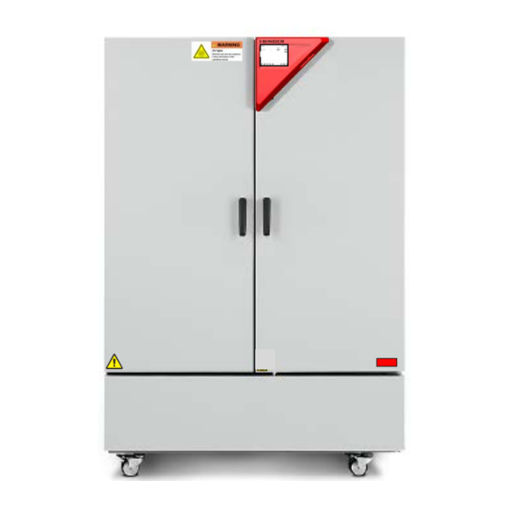
Chamber overview Figure 4: Constant climate chamber / Growth chamber size 240 Instrument box Door handle Outer door Refrigerating machine and humidity generation module 2.3 Instrument panel 5,7" controller display with touchscreen USB interface Pilot lamp Figure 5: Instrument panel with MB2 program controller and USB interface KBF P + KBF LQC + KBWF (E6) 11/2016 page 19/189... -
Page 20: Lateral Control Panels
Figure 6: Lateral control panels at the sides of the refrigerating / humidity generation module with optional equipment Main power switch DIN socket for additional Pt 100 sensor (may be available via BINDER INDIVIDUAL customized solutions) DIN socket for analog outputs (option) -
Page 21: Rear View With Water Connections
Rear view with water connections (10) (11) (12) (13) (14) Figure 7: Rear view of the chamber with water connections (10) Socket for optional freshwater can (chap. 21.9.1) (11) Power cable (12) Purging outlet for humidifying module – for service purpose only (13) Freshwater connection “IN”... -
Page 22: Completeness Of Delivery, Transportation, Storage, And Installation
Note on second-hand chambers (Ex-Demo-Units): Second-hand chambers are chambers that were used for a short time for tests or exhibitions. They are thoroughly tested before resale. BINDER ensures that the chamber is technically sound and will work flawlessly. Second-hand chambers are marked with a sticker on the chamber door. Please remove the sticker before commissioning the chamber. -
Page 23: Guidelines For Safe Lifting And Transportation
• If the steam humidifying system has NOT been emptied: +3 °C / 37.4 °F to +60 °C / 140 °F. • After BINDER Service has emptied the steam humidifying system: -10 °C / 14 °F to +60 °C / 140 °F. -
Page 24: Location Of Installation And Ambient Conditions
Storage below +3 °C / 37.4 °F with filled steam humidifying system. Freezing in the steam generator. Damage to the chamber. Contact BINDER Service before any transportation below +3 °C / 37.4 °F. Permissible ambient humidity: max. 70 % r.H., non-condensing CAUTION Condensation by excess humidity. - Page 25 • Permissible ambient humidity: 70 % r.H. max., non-condensing When operating the chamber at temperature set-points below ambient temperature, high ambient humidi- ty may lead to condensation on the chamber. • Installation height: max. 2000 m / 6562 ft. above sea level. A water tap (1 bar to 10 bar) is necessary for the installation of the humidification system (chap.
-
Page 26: Installation And Connections
Installation and connections Spacer for wall distance Please fix both spacers with the supplied screws at the chamber rear. This serves to ensure the pre- scribed minimum distance to the rear wall of 100 mm / 3.94 in. Figure 8: Spacer for wall distance Figure 9: Rear KMF with mounted spacers Wastewater connection Fasten the wastewater hose to the wastewater connection “OUT”... -
Page 27: Freshwater Supply
1 µS/cm (ultrapure water), may cause acid corrosion due to its low pH.) • Water treated by the optional water treatment system BINDER Pure Aqua Service (disposable system). A reusable measuring equipment to assess the water quality is included (chap. 21.10). -
Page 28: Manual Fresh Water Supply Via External Freshwater Can (Option)
4.3.2 Manual fresh water supply via external freshwater can (option) If no house water connection with suitable water is available, you can manually supply water by filling a freshwater can (option, volume: 20 liters / 0.71 cu.ft. You can attach the freshwater can on the rear of the chamber or place it next to the chamber (chap. -
Page 29: Safety Kit: Hose Burst Protection Device With Reflux Protection Device (Available Via Binder Individual Customized Solutions)
4.3.4 Safety kit: Hose burst protection device with reflux protection device (available via BINDER INDIVIDUAL customized solutions) A safety kit with a reflux protection device is available for protection of the drinking water system, and against flooding caused by burst water hoses. - Page 30 Figure 11: Assembly of the safety kit (hose burst protection and reflux protection devices) Release of the reflux protection device: In case the hose burst protection device interrupts the water supply, first find the reason and remove it as necessary. Close the water tap. Release the valve by a half left-turn of the upper knurled part. You can hear the release of the valve as a clicking noise.
-
Page 31: Installation And Connection Of The Light Cassettes
Installation and connection of the light cassettes You can insert the light cassettes in different heights onto the beads at the lateral walls of the chamber. Insert and pull out the light cassettes only by the handles. Connect the cables of the light cas- settes to its closest connection socket at the right side in the back of the cham- ber. -
Page 32: Connecting The Light Sensors - Kbf Lqc
Connecting the light sensors – KBF LQC Two light sensors to measure illumination and UV-intensity can be freely positioned in the inner chamber. The sensors are equipped with a cable of at least 1.3 m length. They are plugged in the LEMO sock- ets marked “V-λ... -
Page 33: Electrical Connection
Model version Power plug indicated power fre- (x = 0 or 1) type fuse quency KBWF 240 9x20-0336 KBF P 240 9x20-0328 Shock-proof plug 200-230 V at 50 Hz 16 Amp KBF LQC 240 9x20-0332 KBF P 240-UL 9x20-0329 200-240 V at 50Hz... -
Page 34: Connection Of The Voltage Changer (Option For Kbf P 240 / Kbf Lqc 240)
Connection of the voltage changer (option for KBF P 240 / KBF LQC 240) The voltage changer enables the constant climate chamber to operate at a power frequency of 115 Volt. It is packed separately and supplied together with the constant climate chamber. - Page 35 To establish the electrical connection of the constant climate chamber with the voltage changer, proceed in the following order: 1. Connect the power cable of the constant climate chamber to the connection socket (D) of the voltage changer 2. Establish the power connection of the voltage changer. The socket must provide a protective conduc- tor.
-
Page 36: Functional Overview Of The Mb2 Chamber Controller
The MB2 program controller permits programming temperature and humidity cycles. You can enter values or programs directly at the controller or use the APT-COM™ 3 DataControl- System software (option) specially developed by BINDER. KBF P + KBF LQC + KBWF (E6) 11/2016... - Page 37 Operating mode Temperature values Humidity values Actual values Set-point values Functional icons Figure 17: Normal display of the MB2 program controller (sample values) with KBF P / KBWF Operating mode Temperature values Humidity values Actual values / actual or inte- grated light values Set-point values / target dose values...
-
Page 38: Operating Functions In Normal Display
Operating functions in normal display Current operating mode Text list for information icons Date, time, authorization level of the logged-in user, memory Quick setpoint entry (example: KBF P / KBWF) Continue to next screen Back to Normal display Information Program start Setpoint entry Event list Display of active alarms... -
Page 39: Display Views: Normal Display, Program Display, Chart-Recorder Display
Display views: Normal display, program display, chart-recorder display Press the Change view icon to toggle between normal display, program display and chart- recorder display. Press the Normal display icon to return from program display and chart recorder display back to Normal display. -
Page 40: Controller Icons Overview
Controller icons overview Navigation icons in Normal display Icon Signification Function Main menu Access from Normal display to the main menu Alarm Access from Normal display to the list of active alarms Event list Access from Normal display to the event list Access from Normal display to the setpoint entry menu: setpoint Setpoint setting entry for Fixed value operation, turning on/off humidity control,... - Page 41 Information icons Icon Signification Information Idle mode Controller in Idle mode Temperature range Current actual temperature value outside the tolerance range Humidity range Current actual humidity value outside the tolerance range Door open Chamber door is open Humidity off The humidification / dehumidification system is turned off KBF P / KBF LQC: VIS light turned on (operation line “Light VIS”...
-
Page 42: Operating Modes
Operating modes The MB2 program controller operates in the following operating modes: • Idle mode The controller is not functional, i.e., there is no heating or refrigeration and no humidification or dehu- midification. The fan is off. The chamber approximates ambient values. The fluorescent tubes are off. -
Page 43: Controller Menu Structure
Controller menu structure Use the navigation icons in the screen footer in Normal display to access the desired controller func- tions. Normal display (example: KBF P / KBWF) The available functions depend on the current authorization level “Service”, “Admin” or “User” (chap. 14.1). -
Page 44: Main Menu
• Access to service data, controller reset to factory settings (chap. 5.5.3) • Available only for users with “Service” and “Admin” authorization level. Full functional range only for BINDER Service (users with “Service” authorization level). “Programs” submenu • Access to the controller’s program functions (chap. 9, 10, 11) -
Page 45: Settings" Submenu
5.5.3 “Service” submenu The “Service” submenu is available for users with “Service” or “Admin” authorization level. When logged-in with “Admin” authorization level the user will find information to tell the BINDER Service in service case. Path: Main menu > Service Serial number of the chamber, setup version chap. -
Page 46: Principle Of Controller Entries
Principle of controller entries In the selection and entry menus there are icons displayed in the footers which you can use to take over the entry or cancel it. Selection menu (example) Entry menu (example) There are the following possibilities: Press the Confirm icon to take over the entries and exit the menu or continue the menu se- quence. -
Page 47: Performance When Opening The Door
To reduce odors quickly we recommend heating up the chamber to its nominal temperature for one day and in a well-ventilated location. WARNING: If customer should use a BINDER chamber running in non-supervised continuous operation, we strongly recommend in case of inclusion of irrecoverable specimen or samples to split such specimen or samples and store them in at least two chambers, if this is feasible. -
Page 48: Controller Settings Upon Start Up
Controller settings upon start up The window „Language selection“ enables the language selection, in case that it’s activated in the “Start- up” menu. Afterwards occurs a request of the time zone and the temperature unit. The controller will function in the operating mode, which was active before the last shut-down. It controls temperature and humidity in fixed value operating mode to the last entered values and in the program mode to the set points achieved beforehand. -
Page 49: Turning On/Off Humidity Control
Turning on/off humidity control Turning off humidity control is required when operating the chamber without water connection in order to avoid humidity alarms. For further information see chap. 18. Press the Setpoint setting icon to access the “Setpoint” setting menu from Normal display. “Setpoints”... -
Page 50: Function Of Light Measurement, And Integration: Light Quantum Control - Kbf Lqc
Function of light measurement, and integration: Light Quantum Control – KBF LQC The chamber is equipped with fluorescent tubes for UVA and the visible spectral range. These fluorescent tubes can be turned on with the operation lines “Light VIS” and “Light UVA”. When operation line “LQC On”... - Page 51 Integration takes place as soon as operation line “LQC On” is activated, and at least one target dose value other than 0.0 has been entered. With target dose value 0.0, or in case the entered target dose value has been reached, the fluorescent tubes do not turn on automatically. The illumination can be turned on and off with the operation lines “Light VIS”...
-
Page 52: Set-Point Entry In "Fixed Value" Operating Mode
Set-point entry in “Fixed value” operating mode In Fixed value operating mode you can enter a temperature set-point, a humidity set-point, the fan speed, and the switching-state of up to 16 operation lines. All settings made in Fixed value operating mode remain valid until the next manual change. They are saved also when turning off the chamber or in case of toggling to Idle Mode or Program Mode. -
Page 53: Set-Point Entry Through The "Setpoints" Menu
Set-point entry through the “Setpoints” menu Press the Setpoint setting icon to access the “Setpoint” setting menu from Normal display. Press the Back icon to go return to Normal display from any menu. “Setpoints” menu. Select “Fixed value operation setpoints”. Display with KBF LQC Display with KBF P / KBWF Select the parameter to enter the setpoint. -
Page 54: Direct Setpoint Entry Via Normal Display
“Fan” entry menu. “UVA Dose” entry menu. Enter the desired setpoint and press the Con- firm icon. Enter the desired target dose and press the Confirm icon. Proceed accordingly to enter the VIS target dose. When entering a value outside the setting range, the message: “Value outside of limits! (Min: xxx, Max: xxx)”... -
Page 55: Automatic Correction Of The Actual Value When Turning On Or Off The Illumination
• KBF P / KBF LQC: Operation line “Light VIS” serves to turn on/off the cool white fluorescent tubes • KBF P / KBF LQC: Operation line “Light UVA” serves to turn on/off the BINDER Synergy Light fluores- cent tubes •... - Page 56 Use the “Setpoints” menu to configure the operation lines. Display with KBF P “Setpoints” menu. Select the field “Functions on/off”. Display with KBF LQC Display with KBWF “Functions on/off” entry menu. Mark / unmark the checkbox to activate / deactivate the desired function and press the Confirm icon. Activated operation line: switching status “1”...
-
Page 57: Timer Program: Stopwatch Function
Timer program: stopwatch function During an entered duration the controller constantly equilibrates to the setpoints entered in Fixed value operation mode (temperature, humidity, fan speed, configuration of the operation lines). This duration can be entered as a “Timer program”. During the program runtime, any setpoint changes do not become ef- fective;... -
Page 58: Performance During Program Delay Time
“Program start” menu. Enter the desired start time of the program and press the Confirm icon. The program delay Select the field “Program start”. time until program start begins. Normal display. Information on the bottom of the screen indicates the currently running program and the time already passed. -
Page 59: Cancelling A Running Timer Program
9.2.2 Cancelling a running timer program Press the Program cancelling icon to cancel the program. A confirmation prompt is displayed. Press the Confirm icon to confirm that the program shall really be can- celled. After confirming the message the controller changes to Fixed value operation mode. Temperature and humidity will then equilibrate to the setpoints of Fixed value operation mode. -
Page 60: Time Programs
Time programs The MB2 program controller permits programming time programs with real-time reference. It offers 25 program memory positions with up to 100 program sections each. For each program section you can enter a temperature set-point, fan speed, section duration, type of tem- perature transition (ramp or step) and the tolerance range. -
Page 61: Performance During Program Delay Time
“Program start” menu. “Program start” menu. Select the field “Program start”. Enter the desired program start time and press the Confirm icon. The program delay time until program start begins. The program end is adapted automatically depending on the entered program duration. Normal display. -
Page 62: Stopping A Running Time Program
10.2 Stopping a running time program 10.2.1 Pausing a running time program Press the Program pause icon to interrupt the program.. The program is paused. The program runtime stops running down, the time display flashes. There are the following options: Press the Program start icon to continue the program Press the Cancelling icon to cancel the program 10.2.2 Cancelling a running time program... -
Page 63: Creating A New Time Program
10.4 Creating a new time program Path: Main menu > Programs > Time program “Time program” menu: Enter the program name and, if desired, addi- overview of the existing programs. tional program information in the corresponding fields. Select an empty program place. Press the Confirm icon. - Page 64 Program editor: “Edit program” menu Select the desired function and press the Confirm icon. The program editor offers following options: • Change the program name • Copy program • Replace program: Replacing an new or an existing program with the copied program. This menu point is visible only after a program has been copied.
-
Page 65: Section Editor: Section Management
10.6 Section editor: Section management Path: Main menu > Programs > Time program Select the desired program. Example: Display with KBF P / KBWF Section view (example: section 1). Program view. There are the following options: Select the desired program section Select a parameter to enter or modify the (example: section 1) -
Page 66: Add A New Section
10.6.1 Add a new section Section editor: “Edit section” menu. Select “Add new section” and press the Confirm icon. Then select whether to insert the new section before or after the current section. Press the Confirm icon. The new section opens. 10.6.2 Copy and insert or replace a section Example: Display with KBF P / KBWF Section view (example: section 1). - Page 67 Section editor: “Edit section” menu Section view (example: section 1). Select “Copy section” and press the Confirm Press the Close icon to change to the program icon. view, if you want to select another section to be replaced or before or after which the copied The current section (example: section 1) is section shall be inserted copied.
-
Page 68: Deleting A Section
Select “Replace section” to replace the selected section with the copied section Select “Insert section” to additionally add the copied section. In this case select whether to insert it before or after the se- lected section. Press the Confirm icon Section editor: “Edit section”... -
Page 69: Value Entry For A Program Section
10.7 Value entry for a program section Path: Main menu > Programs > Time program Select the desired program and section. The section view gives access to all parameters of a program section. You can enter or modify the values. Program name and section number Section duration Type of setpoint transition: ramp or step... -
Page 70: Section Duration
10.7.1 Section duration Section view (partial view). Select the field “Duration” indicating the time. “Duration” entry menu. Enter the desired section duration with the arrow keys and press the Confirm icon. Setting range: 0 up to 99 hours 59 min 59 sec. 10.7.2 Set-point ramp and set-point step You can define the type of temperature and humidity transitions for each individual program section. - Page 71 Programming in the “step” mode allows only two kinds of temperature and humidity transitions: • Programming gradual changes of temperature and humidity (ramps) is impossible in the “step” mode • Program sections with constant temperature and humidity The setpoints (target values) of two subsequent program sections are identical; so the temperature and humidity remain constant during the entire duration of the first program section.
-
Page 72: Light Commutation And Special Controller Functions Via Operation Lines
• KBF P / KBF LQC: Operation line “Light VIS” serves to turn on/off the cool white fluorescent tubes • KBF P / KBF LQC: Operation line “Light UVA” serves to turn on/off the BINDER Synergy Light fluores- cent tubes •... -
Page 73: Temperature Setpoint
“Functions on/off” entry menu. Mark / unmark the checkbox of the desired function to activate / deactivate it and press the Confirm icon. The controller returns to the section view. Section view indicating the operation lines. Activated operation line: switching status “1” (On) Deactivated operation line: switching status “0”... -
Page 74: Humidity Setpoint
10.7.5 Humidity setpoint “Humidity” entry menu. Section view. Enter the desired value and press the Confirm Select the field “Humidity”. icon. Setting range: 0% r.H. up to 80% r.H. The controller returns to the section view. 10.7.6 Fan speed setpoint Section view. -
Page 75: Uva Target Dose Value - Kbf Lqc
10.7.7 UVA target dose value – KBF LQC “UVA dose” entry menu. Enter the target dose value for UVA and press the Confirm icon. Setting range: 0 up to 99999 Wh/m². The controller returns to the section view. Section view. Select the field “UVA dose”. -
Page 76: Tolerance Ranges
10.7.9 Tolerance ranges For temperature and humidity and, with KBF LQC, for the VIS and UVA dose, you can specify a tolerance range for each program section with different values for the tolerance minimum and maximum. When the actual value exceeds the given threshold, the program is interrupted. This is indicated on the display (see below). -
Page 77: Repeating One Or Several Sections Within A Time Program
Set the tolerance ranges for other parameters accordingly. If one of those actual values for which a tolerance range has been specified lies outside this program tol- erance range the whole program course is interrupted. During this program interruption time the controller equilibrates to the set-points of the current section. -
Page 78: Saving The Time Program
Entry menu „Start section for repetition“. Section view. Enter the section number, at which the repetition Select the field “Start section for repetition”. should start and press the Confirm icon. Setting range: 1 up to one section before the cur- rently selected section The controller returns to the section view. -
Page 79: Week Programs
Week programs The MB2 program controller permits programming week programs with real-time reference. It offers 5 week program places in total with up to 100 shift points for each week program. Path: Main menu > Programs> Week program KBF LQC: By programming the operation lines accordingly, light integration is possible (chap 11.6.9). 11.1 Starting an existing week program “Program start”... -
Page 80: Cancelling A Running Week Program
After starting the week program, the previously entered week program setpoints are active and will be equilibrated according to the current time. Information on the bottom of the screen indicates the currently running program. 11.2 Cancelling a running week program Press the Program cancelling icon to cancel the program. -
Page 81: Creating A New Week Program
11.3 Creating a new week program Path: Main menu > Programs > Week program Enter the program name and, if desired, addi- “Week program” menu: tional program information in the correspond- overview of the existing programs. ing fields. Select an empty program place. Press the Confirm icon. -
Page 82: Program Editor: Program Management
11.4 Program editor: program management Path: Main menu > Programs > Week program “Week program” menu: Program view (example: program 1). overview of the existing programs. If a new program has been created, there is just one program section. Select an existing program (example: pro- gram 1). -
Page 83: Section Editor: Section Management
Program view. To add a new section, select “Add new section” and press the Confirm icon. With a new section no weekday is specified. There- fore the section is first marked in red and cannot be The program view opens. saved. -
Page 84: Add A New Section
Section editor: “Edit section” menu Select the desired function and press the Confirm icon. The section editor offers following options: • Copy section • Replace section: Replacing an existing section with the copied section. This menu point is visible only after a section has been copied. -
Page 85: Copy And Insert Or Replace A Section
11.5.2 Copy and insert or replace a section Section editor: “Edit section” menu Program view Select the section to be replaced or before or Select “Copy section” and press the Confirm after which the copied section shall be inserted icon. (example: section 2). -
Page 86: Weekday
“Change program name” menu. In the field “Course” select the desired setting “Ramp” or “Step” and press the Confirm icon. 11.6.2 Weekday In the field “Weekday” select the desired weekday. With “Daily” selected, this section will run every day at the same time. -
Page 87: Temperature Setpoint
11.6.4 Temperature setpoint “Temperature” entry menu. Example: Display with KBF P / KBWF Enter the desired temperature and press the Section view. Confirm icon. Select the field “Temperature”. Setting range: -5 °C up to 70 °C The controller returns to the section view. 11.6.5 Humidity setpoint “Humidity”... -
Page 88: Fan Speed Setpoint
11.6.6 Fan speed setpoint “Fan” entry menu. Example: Display with KBF P / KBWF Enter the desired value for the fan speed and Section view. press the Confirm icon. Select the field “Fan”. Setting range: 40% up to 100% fan speed. The controller returns to the section view. -
Page 89: Vis Target Dose Value - Kbf Lqc
• KBF P / KBF LQC: Operation line “Light VIS” serves to turn on/off the cool white fluorescent tubes • KBF P / KBF LQC: Operation line “Light UVA” serves to turn on/off the BINDER Synergy Light fluores- cent tubes •... -
Page 90: Deleting A Week Program
11.7 Deleting a week program Path: Main menu > Programs > Week program “Week program” menu. “Program view”. Select the program to be deleted. Press the Edit icon“. Program editor: “Edit program” menu. Select “Delete program”. KBF P + KBF LQC + KBWF (E6) 11/2016 page 90/189... -
Page 91: Notification And Alarm Functions
Notification and alarm functions 12.1 Notification and alarm messages overview 12.1.1 Notifications Notifications are indicated by information icons displayed in the screen header in Normal display An information icon serves as an indication of a certain condition. If this condition persists, in some cases an alarm will be triggered after a fix or configurable interval. As long as the condition persists, the information icon therefore continues to be displayed also in state of alarm. -
Page 92: Messages When Reaching A Dose Target Value - Kbf Lqc
Information Start after Condition Text information icon condition occurred KBF P / KBF LQC: VIS light turned on (oper- immediately Light VIS ation line “Light VIS” activated) KBF P / KBF LQC: UVA light turned on (op- immediately Light UVA eration line “Light UVA”... -
Page 93: Alarm Messages
12.1.4 Messages concerning the humidity system Start after condition Condition and measures Message occurred The humidity module is defective. Contact BINDER ser- Humidity system immediately vice The humidity module cannot fill up. In case of freshwater supply via water pipe: The water tap is closed, or the chamber is defective. -
Page 94: State Of Alarm
Maintenance of the humidity system is required. Contact Humidity module after predefined time BINDER service. (approx. 1 year) service Messages concerning the humidity system are shown in the event list. When operating the chamber without water connection, turn off humidity control in the “set- points”... -
Page 95: Tolerance Range Settings
Pressing the Reset alarm icon mutes the buzzer for all active alarms. The icon then disappears. • Acknowledging while the alarm condition persists: Only the buzzer turns off. The visual alarm indication remains on the controller display. The alarm remains in the list of active alarms. When the alarm condition has ended, the visual alarm indication is automatically cleared. -
Page 96: Activating / Deactivating The Audible Alarm (Alarm Buzzer)
Submenu “Various”. “Humidity range” entry menu. Select the field “Humidity range”. Enter the desired value for the humidity range and press the Confirm icon. Setting range: 5% r.H. to 20% r.H. There are the following possibilities: Press the Confirm icon to take over the entries and exit the menu. Press the Close icon to exit the menu without taking over the entries. -
Page 97: Temperature Safety Devices
The user cannot restart the device again. The protective cut-off device is located internally. Only a service specialist can replace it. Therefore, please contact an authorized service provider or BINDER Service. 13.2 Overtemperature safety controller class 3.1 The chambers are regularly equipped with an electronic overtemperature safety controller (temperature safety device class 3.1 according to DIN 12880:2007). -
Page 98: Setting The Safety Controller
Example: Desired temperature value: 40 °C, desired safety controller value: 45 °C. Possible settings for this example: Temperature set point Safety controller mode Safety controller set-point Limit (absolute) 45 °C 40 °C Offset (relative) 5 °C 13.2.2 Setting the safety controller Press the Setpoint setting icon to access the “Setpoint”... -
Page 99: Message And Measures In The State Of Alarm
“Offset” entry menu. “Setpoints” menu. Enter the desired safety controller setpoint and press Select the corresponding field “Limit” or “Off- the Confirm icon. set” (example: “Offset”) Regularly check the safety controller setting for set-point type “Limit” or “Offset” • in Fixed value operating mode according to the entered set-point temperature value •... -
Page 100: Temperature Safety Device Class 3.3 (Option)
13.3 Temperature safety device class 3.3 (option) With the option over/under temperature protective device (temperature safety device class 3.3 acc. to DIN 12880:2007) the chamber is equipped with two additional safety devices (class 3.1 and class 3.2). The combination of the safety devices is regarded as a safety device class 3.3. The temperature safety device, class 3.3, serves to protect the chamber, its environment and the contents from exceeding the maximum permissible temperature. -
Page 101: Temperature Safety Device Class 3.1
13.3.1 Temperature safety device class 3.1 If you turn the control knob (8) to its end-stop (position 10), the safety device (8a) class 3.1 protects the appliance. If you set the temperature a little above the set-point, it protects the charging material. If the safety device class 3.1 has taken over control, identifiable by the red alarm lamp (8a) lighting up, the message “Temp. -
Page 102: Temperature Safety Device Class 3.2
13.3.2 Temperature safety device class 3.2 The safety device class 3.2 is equivalently set to a minimum temperature the (9a) chamber will not fall below. This protection against prohibited low tempera- tures can, for example, serve to protect sensitive cultures from cooling down too much. -
Page 103: User Management
• All passwords can be changed in the “log out” submenu (chap. 14.3). “Service” authorization level • Authorization level only for BINDER service • Extensive authorization for controller operation and configuration, access to service data • The passwords for “Service”, “Admin” and “User” authorization levels can be changed in the “log out”... - Page 104 Operation after user login At user login, the authorization level is selected and confirmed by entering the respective pass- word. Following user login, controller operation is avail- able, recognizable by the open-lock icon in the header. The available controller functions corre- spond to the user’s authorization level.
- Page 105 Information window To check the authorization level of the user currently logged-in, select in Normal display the arrow far right in the display header. The information window shows date and time, the controller’s free memory space and under “Authoriza- tion” the authorization level of the current user. If passwords have been assigned for all authorization levels, a user without login (password entry) has no authorization.
-
Page 106: Log In
14.2 Log in Path: Main menu > User > Log in Controller without a user logged-in Selection of user type (example) All selection possibilities are password protected Controller with logged-in user There are the following possibilities: Press the Confirm icon to take over the entries and exit the menu. Press the Close icon to exit the menu without taking over the entries. -
Page 107: Log Out
14.3 Log out Path: Main menu > User > Log out User logoff with “Admin” authorization Controller Controller with without a user logged-in user logged-in User logoff with “Admin” authorization Controller Controller with without a user logged-in user logged-in 14.4 User change If the password function has been deactivated (chap.14.5.2) this function is not available. -
Page 108: Password Assignment And Password Change
User selection (example) All selection possibilities are password protected Controller with logged- in user 14.5 Password assignment and password change This function is not available for a user logged-in with “User” authorization. 14.5.1 Password change A logged-in user can change the passwords of his current level and of the next lower level(s). Example: A user with “Admin”... - Page 109 Selection of the authorization level Enter desired password. (example: view with “Admin” authorization) If desired, press the Change keyboard icon to access other entry windows. In the “Keyboard switch” window you can select different keyboards to enter uppercase and lowercase letters, digits, and special characters.
- Page 110 Entry of digits Entry of special characters To confirm the password after the entry, repeat the entry and press the Confirm icon. KBF P + KBF LQC + KBWF (E6) 11/2016 page 110/189...
-
Page 111: Deleting The Password For An Individual Authorization Level
14.5.2 Deleting the password for an individual authorization level A user logged-in with “Service” or “Admin” authorization can delete the passwords of his current level and of the next lower level(s). To do this no password is entered during a password change. Path: Main menu >... -
Page 112: New Password Assignment For "Service" Or "Admin" Authorization Level When The Password Function Was Deactivated
14.5.3 New password assignment for “service” or “admin” authorization level when the password function was deactivated If the password protection for an authorization level has been deactivated, i.e., no password is assigned, no login for this level is possible. Therefore access to this authorization level is available without login. If the password for the “Service”... -
Page 113: Activation Code
14.6 Activation code Certain functions of the controller can be unlocked with a previously generated activation code. The activation code enables access to functions available only in the “Service” authorization level by users without a “Service” authorization. Such functions include e.g., adjustment or extended configurations. The activation code is available in authorization levels. -
Page 114: General Controller Settings
General controller settings Most of the general settings can be accessed in the “Settings” submenu, which is available for users with “Service” or “Admin” authorization level. It serves to enter date and time, select the language for the con- troller menus and the desired temperature unit and to configure the controller’s communication functions. 15.1 Selecting the controller’s menu language The MB2 program controller communicates by a menu guide using real words in German, English, French, Spanish, and Italian. -
Page 115: Setting Date And Time
Change of the temperature unit between °C and °F. If the unit is changed, all values are converted accordingly C = degree Celsius 0 °C = 31°F Conversion: [value in °F] = [value in °C] ∗ 1,8 + 32 F= degree Fahrenheit 100 °C = 212°F 15.3 Setting date and time Following start-up of the chamber after language selection:... - Page 116 “Date and time” submenu. “Date and time” submenu. In the field “Daylight saving time switch” select Select the desired time zone and press the the desired setting “Automatic” or “Inactive”. Confirm icon. “Date and time” submenu. “Date and time” submenu. Select the desired start of the daylight saving Select the desired end of the daylight saving time.
-
Page 117: Display Configuration
15.4 Display configuration 15.4.1 Adapting the display parameters This function serves to configure parameters like display brightness and operating times. Path: Main menu > Settings > Display > Display “Display” submenu. Move the grey slide to the left or right to define the brightness of the display Select the field “Brightness”. - Page 118 “Display” submenu. In the field “Activate continuous operation” select the desired setting “Yes” or “No”. “Display” submenu. Entry menu “Begin continuous operation”. Select the field “Begin continuous operation” Enter the time with the arrow keys and press the (possible only if continuous operation is activat- Confirm icon.
-
Page 119: Touchscreen Calibration
15.4.2 Touchscreen calibration This function serves to optimize the display for the user’s individual angular perspective. Path: Main menu > Calibrate touchscreen Normal display. Follow the instructions on the display. You need to touch all four corners of the touchscreen to calibrate it. Appropriate boxes appear succes- sively in each corner. -
Page 120: Network And Communication
This menu allows to configure the communication parameters of the RS485 interface. The device address is required to recognize chambers with this interface type in a network, e.g. when connecting it to the optional communication software BINDER APT-COM™ 3 DataControlSystem (chap. 21.1). In this case do not change the other parameters. -
Page 121: Ethernet
“Serial interfaces” submenu. “Device adress” entry menu Select the field “Device address”. Enter the device adress and press the Con- firm icon. Factory setting: “1”. 15.5.2 Ethernet 15.5.2.1 Configuration Path: Main menu > Settings > Ethernet “Ethernet” submenu. In the field “IP address assignment” select the desired setting “Automatic (DHCP)“... -
Page 122: Web Server
This controller menu serves to configure the web server. Then you can enter the chamber’s IP-address in the Internet. The IP address is available via Chamber information > Ethernet. The BINDER web server opens. Enter the user name and password which have been assigned for the web server in the controller menu. - Page 123 Submenu “Web server”. “User name” entry menu. Select the field “User name”. Enter the desired user name and press the Confirm icon. Submenu “Web server”. “Password” entry menu (example). Select the field “Password”. Enter the desired password and press the Con- firm icon.
-
Page 124: E-Mail
15.5.4 E-Mail As soon as an alarm was triggered, an e-mail is sent to the configured e-mail address. Path: Main menu > Settings > Email “Email” submenu. “Email address” entry menu. Select the field of the e-mail address to be Enter the e-mail address. - Page 125 Select the field “SMTP mail server URL”. Enter the SMPT mail server URL and press the Confirm icon. Select the field “Email sender”. Enter the desired Email sender and press the Confirm icon. There are the following possibilities: Press the Confirm icon to take over the entries and exit the menu. Press the Close icon to exit the menu without taking over the entries.
-
Page 126: Usb Menu
15.6 USB menu When you insert a USB-stick, the “USB menu” opens. Depending on the user’s authorization level, different functions (highlighted in black) are available for the logged-in user. Available functions with “User” authorization level Available functions with “Admin” authorization level Available functions with “Service”... -
Page 127: General Information
General information 16.1 Service contact page Path: Main menu > Contact 16.2 Current operating parameters “Info” menu. Normal display. Select the desired information. Press the Information icon. Selection “Program operation”. Information on a currently running program. KBF P + KBF LQC + KBWF (E6) 11/2016 page 127/189... -
Page 128: Event List
Display with KBF P / KBWF Display with KBF LQC Selection “Setpoints“. Information on the entered setpoints and operation lines. Selection “Actual values”. Selection “Safety controller”. Information on the current actual values. Information on the safety controller. 16.3 Event list Press the Event list icon to access the event list from Normal display. -
Page 129: Technical Chamber Information
(chap. 17.2) the Event list is cleared. 16.4 Technical chamber information Path: Main menu > Device info Chamber name and setup Versions of CPU, I/O module and safety con- for BINDER troller Service Information on digital and analog inputs and for BINDER... -
Page 130: Chart Recorder Display
Chart recorder display This view offers graphic representation of the measurement course. Data representation imitates a chart recorder and allows recalling any set of measured data at any point of time taken from the recorded peri- 17.1 Views Press the Change view icon to access the pen recorder display. Show and hide the legend: Display with KBF P / KBWF Display with KBF LQC –... - Page 131 Switch between legend pages: Display with KBF LQC Display with KBF P Display with KBWF Display with KBF P Display with KBF LQC Display with KBWF Switch between legend pages Show and hide specific indications: Display with KBF P / KBWF Display with KBF LQC KBF P / KBF LQC: Show the indications “Door open”...
- Page 132 History display: Display with KBF P / KBWF Display with KBF LQC The pen recorder is paused. Data recording continues in the background. Move the central red line by tapping and holding to the desired position. The legend at the right side shows the values of the current line position.
- Page 133 History display: Search function “Search” submenu. Enter date and time of the required instant and press the Confirm icon Search and go to a desired instant History display: Zoom function “Zoom” submenu. Select the zoom factor and press the Confirm icon. Select the zoom factor History display: Show and hide arrow keys Display with KBF P / KBWF...
-
Page 134: Setting The Parameters
17.2 Setting the parameters This menu allows setting the storage interval, the type of values to be shown and the scaling of the tem- perature and humidity charts. Path: Main menu > Settings > Measurement chart Display with KBF P / KBWF Display with KBF LQC “Measurement chart”... - Page 135 For scaling the representation select the desired temperature or humidity value and, with KBF LQC, the desired VIS or UVA dose target value. Example: “Min. temperature” entry menu. “Measurement chart” submenu (example) Enter the desired value and press the Confirm icon.
-
Page 136: Humidification / Dehumidification System
Humidification / dehumidification system The chamber is equipped with a capacitive humidity sensor. This results in a control accuracy of up to +/- 3 % r.H. of the set point. The temperature-humidity diagrams show the possible working ranges for humid- ity. - Page 137 Heat emission of electrical devices connected inside the chamber may modify the temperature and humidity range. The chambers are equipped with a door heating system to prevent condensation in the door area. If the set points for temperature or humidity are outside the optimum range, condensation can arise in the door area.
-
Page 138: Function Of The Humidifying And Dehumidifying System
• Water intake temperature NOT below +5 °C / 41 °F and not exceeding 40 °C / 104 °F. BINDER GmbH is NOT responsible for the water quality provided by the customer. Any problems and malfunctions that might arise following use of water of deviating quality is excluded from liability by BINDER GmbH. -
Page 139: Defrosting At Refrigerating Operation
Defrosting at refrigerating operation BINDER constant climate chambers are very diffusion-proof. To ensure high temperature precision there is no automatic cyclic defrosting device. The DCT™ refrigerating system largely avoids icing of the evapo- ration plates. However, at very low temperatures the moisture in the air can condense on the evaporator plates leading to icing. -
Page 140: Illumination System
• Optimum homogeneity of the spectral distribution and the intensities in LUX and UVA on the shelf sur- face, even with high intensity values, obtained by the BINDER ICH light and the special lens of the headlight. This guarantees that all samples receive the same radiation doses, thus permitting very pre- cise test conditions for photo stability tests. -
Page 141: Illumination For Optimal Plant Growth - Kbwf
20.2 Illumination for optimal plant growth – KBWF The KBWF chambers are equipped with day light fluorescent tubes. Optionally available are efficient ® FLUORA growth illumination tubes for optimal plant growth or special Arabidopsis lamps. The fluorescent tubes are built in light cassettes that can be freely positioned within wide areas. They homogeneously illuminate the racks below them. - Page 142 This position is only meant for the light cassettes. Due to their connections, shelves cannot be positioned here. You can move the light cassettes to the indicated positions. Plug rear front Figure 26: Arrangement of the fluorescent tubes in the light cassette of KBF P / KBF LQC Plug rear front...
-
Page 143: Illumination Control
20.4 Illumination control The fluorescent tubes can be turned on and off with the operation lines of the program controller. For activating the operating contacts please see chap. 8.4, 10.7.3, and 11.6.9. KBF LQC: The fluorescent tubes can be turned on by entering a dose set-point value in Manual Mode higher than a dose value already reached. -
Page 144: Characteristic Features Of The Light Sensors - Kbf Lqc
20.5 Characteristic features of the light sensors – KBF LQC The sensors can be plugged inside the inner chamber what makes it easy to take them out for calibration or replacement. The intensities of illumination [LUX] and UV [W/m ] are measured by optical sensors inside chambers with ICH illumination equipment (actual value display) and are temporally integrated (dose value display). -
Page 145: Spatial Sensitivity
The use of the spherical sensors in the BINDER measurement system imitates this quantification of the photochemically effective radiation in the best approximation. It enables and permits an exposition exactly responding to the demands of ICH guideline Q1B. - Page 146 In case of exclusive use of entirely flat samples without spatial extension (e.g. spreaded sam- ples, film), an overrating of the light which really impinges on the plane surface is possible. Please contact BINDER INDIVIDUAL customized solutions. If an independent reference measuring device shall be used to directly compare the light inten- sities, it must bear the same spatial sensitivity characteristics (spherical) as the sensors of the BINDER system.
-
Page 147: Options
BINDER Data Loggers are equipped with a keyboard and a large LCD display, alarm functions and a real- time function. Measurement data are recorded in the Data Logger and can be read out after the meas- urement via the RS232 interface of the Data Logger. -
Page 148: Analog Outputs For Temperature And Humidity (Option)
21.4 Analog outputs for temperature and humidity (option) With this option the chamber is equipped with analog outputs 4-20 mA for temperature and humidity. These outputs allow transmitting data to external data registration systems or devices. The connection is realized as a DIN socket (3) in the right lateral control panel as follows: ANALOG OUTPUT 4-20 mA DC PIN 1: Temperature –... -
Page 149: Water Protected Internal Socket (Option)
In case of power failure, transmission of the alarm via zero-voltage relay outputs remains active for the duration of the power failure. Afterwards, both contacts will close automatically. When using the communication software APT-COM™ 3 DataControlSystem (option, chap. 21.1) via the Ethernet interface of the chamber for data acquisition, the alarm is not automati- cally transmitted to the APT-COM™... -
Page 150: Additional Flexible Pt 100 Temperature Sensor (Available Via Binder Individual Customized Solutions)
(sample values) The object temperature data are put out together with the data of the temperature controller and can be documented by the communication software APT-COM™ (option, chap. 21.1) developed by BINDER. Technical data of the Pt100 sensor: • Three-wire technique •... -
Page 151: External Freshwater And Wastewater Cans (Option)
21.9 External freshwater and wastewater cans (option) If no suitable in-house water connection is available, you can manually supply water by filling the optional external freshwater can. There is an additional external water can for the waste water. Volume: 20 liters / 0.71 cu.ft. The cans are placed in holding devices. - Page 152 Cable connections Connect the plug of the cable to the socket (10) at the rear of the chamber. The socket (10) is marked with a sticker: Socket (10) (14) (13) Figure 38: Connections at the chamber rear Hose connections Plug the freshwater hose into the hose connection (16) above the freshwater can and secure it with a hose clamp.
-
Page 153: Mounting The Wastewater Can
21.9.2 Mounting the wastewater can Fixing (if required) Hang the can with its holding device on its 4 carriers at the free space next to the freshwater can. Hose connections Plug the wastewater hose to the hose connection (17) of the wastewater can and secure it with a hose clamp. -
Page 154: Mounting With Wastewater Recycling
21.9.3 Mounting with wastewater recycling When the chamber interior is clean, you can reuse the wastewater from the chamber. Connect the wastewater connection “OUT” (14) of the chamber with the freshwater hose connection (18) of the fresh- water can. The wastewater can is not used in this case. CAUTION Soiling of the vapor humidification system. -
Page 155: Binder Pure Aqua Service (Option)
21.10 BINDER Pure Aqua Service (option) The optional BINDER water treatment system (disposable unit) is available to treat tap water. The lifetime of the unit depends on water quality and the amount of treated water used. The measuring equipment to assess the water quality is reusable. -
Page 156: Replacement Of The Fluorescent Tubes
We recommend taking out a maintenance agreement. Please consult BINDER Service: BINDER telephone hotline: +49 (0) 7462 2005 555 BINDER fax hotline: +49 (0) 7462 2005 93555 BINDER e-mail hotline: service@binder-world.com BINDER service hotline USA: +1 866 885 9794 or +1 631 224 4340 x3 (toll-free in the USA) -
Page 157: Calibrating The Light Sensors And Adjusting The Controller Display - Kbf Lqc
Do not use cleaning agents that may cause a hazard due to reaction with components of the device or the charging material. If there is doubt regarding the suitability of cleaning products, please contact BINDER service. KBF P + KBF LQC + KBWF (E6) 11/2016... - Page 158 We recommend using the neutral cleaning agent Art. No. 1002-0016 for a thorough cleaning. Any corrosive damage that may arise following use of other cleaning agents is excluded from liability by BINDER GmbH. Any corrosive damage caused by a lack of cleaning, is excluded from liability by BINDER GmbH. CAUTION Danger of corrosion.
-
Page 159: Decontamination
For chemical disinfection, we recommend using the disinfectant spray Art. No. 1002-0022. Any corrosive damage that may arise following use of other disinfectants is excluded from liability by BINDER GmbH. With every decontamination method, always use adequate personal safety controls. -
Page 160: Sending The Chamber Back To Binder Gmbh
22.5 Sending the chamber back to BINDER GmbH If you return a BINDER product to us for repair or any other reason, we will only accept the product upon presentation of an authorization number (RMA number) that has previously been issued to you. An au- thorization number will be issued after receiving your complaint either in writing or by telephone prior to your sending the BINDER product back to us. -
Page 161: Decommissioning
(Elektro- und Elektronikgerätegesetz, ElektroG from 20 Octo- ber 2015, BGBl. I p. 1739) or contact BINDER service who will organize taking back and disposal of the chamber according to the German national law for electrical and electronic equipment (Elektro- und El- ektronikgerätegesetz, ElektroG from 20 October 2015, BGBl. -
Page 162: Disposal Of The Chamber In The Member States Of The Eu Except For The Federal Republic Of Germany
According to Annex I of Directive 2012/19/EU of the European Parliament and of the Council on waste electrical and electronic equipment (WEEE), BINDER devices are classified as “monitoring and control instruments” (category 9) only intended for professional use“. They must not be disposed of at public col- lecting points. -
Page 163: Disposal Of The Chamber In Non-Member States Of The Eu
23.5 Disposal of the chamber in non-member states of the EU CAUTION Alteration of the environment. For final decommissioning and disposal of the chamber, please contact BINDER ser- vice. Follow the statutory regulations for appropriate, environmentally friendly disposal. -
Page 164: Troubleshooting
(chap. 4.6). Check chamber fuse and replace Chamber fuse has responded. it if appropriate. If it responds Chamber without function. again, contact BINDER service. Controller defective. Nominal temperature exceeded Contact BINDER service. by 10° due to chamber failure. Over temperature protective de- vice (class 1) responds. - Page 165 Humidity fluctuation, together with temperature fluctuation > Select cooler place of installation Place of installation too hot. 1 °C with a set-point ca. 3 °C or contact BINDER service. above ambient temperature. Capillary tube blocked Contact BINDER service. Not enough refrigerant.
- Page 166 (chap. 4.3.4). burst protection. Have a plumber inspect the valve. Only qualified service personnel authorized by BINDER must perform repair. Repaired chambers must comply with the BINDER quality standards. KBF P + KBF LQC + KBWF (E6) 11/2016 page 166/189...
-
Page 167: Technical Description
December 1996 by TÜV CERT). All test equipment used is subject to the administration of measurement and test equipment that is also a constituent part of the BINDER QM DIN EN ISO 9001 systems. They are controlled and calibrated to a DKD-Standard at regular intervals. -
Page 168: Technical Data
25.4 Technical Data Chamber size Exterior dimensions Width, net mm / inch 925 / 36.42 1250 / 49.21 Height, gross (incl. castors) mm / inch 1460 / 57.48 1925 / 75.79 Depth, net mm / inch 800 / 31.50 890 / 35.04 Depth, gross (including door handle, I-triangle, connection mm / inch 880 / 34.65... - Page 169 +22 °C +/- 3°C / 71.6 °F +/- 5.4 °F and a power supply voltage fluctuation of +/-10%. Technical data is determined in accordance to BINDER factory standard Part 2:2015 and DIN 12880:2007. All indications are average values, typical for chambers produced in series. We reserve the right to change technical specifications at any time.
-
Page 170: Equipment And Options (Extract)
Securing elements for additional fastening of racks (4 pieces) Light cassette KBF P / KBF LQC: Set of fluorescent tubes ICH light (cool white + BINDER Q1B Synergy Light) for 1 light cassette KBWF: Set of fluorescent tubes daylight (light color 865), for 1 light cassette ®... -
Page 171: Spare Parts And Accessories (Extract)
Options / accessories (continued) BINDER Data Logger kit for temperature / humidity: TH 70 (chamber values) or TH 70/70 (chamber and ambient values) External freshwater and wastewater cans (20 liters / 0.71 cu.ft. each) BINDER Pure Aqua Service Exchange cartridge for BINDER Pure Aqua Service... - Page 172 Safety kit for water connection with hose burst protection device and reflux BINDER Individual protection device Customized Solutions KBF P 240 / KBF LQC 240: Voltage changer for operation at 115 Volt 8009-0821 MB2 program controller, screen with E/A board 5014-0197...
-
Page 173: Dimensions Size 240
25.7 Dimensions size 240 KBF P + KBF LQC + KBWF (E6) 11/2016 page 173/189... -
Page 174: Dimensions Size 720
25.8 Dimensions size 720 KBF P + KBF LQC + KBWF (E6) 11/2016 page 174/189... -
Page 175: Certificates And Declarations Of Conformity
Certificates and declarations of conformity 26.1 EU Declaration of Conformity for KBF P KBF P + KBF LQC + KBWF (E6) 11/2016 page 175/189... - Page 176 KBF P + KBF LQC + KBWF (E6) 11/2016 page 176/189...
-
Page 177: Eu Declaration Of Conformity For Kbf Lqc
26.2 EU Declaration of Conformity for KBF LQC KBF P + KBF LQC + KBWF (E6) 11/2016 page 177/189... - Page 178 KBF P + KBF LQC + KBWF (E6) 11/2016 page 178/189...
-
Page 179: Eu Declaration Of Conformity For Kbwf
26.3 EU Declaration of Conformity for KBWF KBF P + KBF LQC + KBWF (E6) 11/2016 page 179/189... - Page 180 KBF P + KBF LQC + KBWF (E6) 11/2016 page 180/189...
-
Page 181: Certificate For The Gs Mark Of Conformity Of The "Deutsche Gesetzliche Unfallversicherung E.v." (German Social Accident Insurance) Dguv
26.4 Certificate for the GS mark of conformity of the “Deutsche Gesetzliche Unfallversicherung e.V.“ (German Social Accident Insurance) DGUV KBF P + KBF LQC + KBWF (E6) 11/2016 page 181/189... - Page 182 KBF P + KBF LQC + KBWF (E6) 11/2016 page 182/189...
-
Page 183: Product Registration
Product registration KBF P + KBF LQC + KBWF (E6) 11/2016 page 183/189... -
Page 184: Contamination Clearance Certificate
Contamination clearance certificate 28.1 For chambers located outside USA and Canada Declaration regarding safety and health Erklärung zur Sicherheit und gesundheitlichen Unbedenklichkeit The German Ordinance on Hazardous Substances (GefStofV), and the regulations regarding safety at the workplace, require that this form be filled out for all products that are returned to us, so that the safety and the health of our employees can be guaranteed Die Sicherheit und Gesundheit unserer Mitarbeiter, die Gefahrstoffverordnung GefStofV und die Vorschriften zur Sicherheit am Arbeitsplatz machen es erforderlich, dass dieses Formblatt für alle Produkte, die an uns zurückge-... - Page 185 Transportweg/Spediteur: Transport by (means and name of transport company, etc.) Versendung durch (Name Spediteur o.ä.) ___________________________________________________________________________________ Date of dispatch to BINDER GmbH / Tag der Absendung an BINDER GmbH ___________________________________________________________________________________ KBF P + KBF LQC + KBWF (E6) 11/2016 page 185/189...
- Page 186 We are aware that, in accordance with Article 823 of the German Civil Code (BGB), we are directly liable with regard to third parties, in this instance especially the employees of BINDER GmbH, who have been entrusted with the handling / repair of the unit / component. / Es ist uns bekannt, dass wir gegenüber Dritten –...
-
Page 187: For Chambers Located In Usa And Canada
After we have received and reviewed the complete information we will decide on the issue of a RMA num- ber. Please be aware that size specifications, voltage specifications as well as performance specifications are available on the internet at www.binder-world.us at any time. Take notice of shipping laws and regulations. - Page 188 Customer (End User) Decontamination Declaration Health and Hazard Safety declaration To protect the health of our employees and the safety at the workplace, we require that this form is com- pleted by the user for all products and parts that are returned to us. (Distributors or Service Organizations cannot sign this form) NO RMA number will be issued without a completed form.
- Page 189 4.5 Shipping laws and regulations have not been violated. I hereby commit and guarantee that we will indemnify BINDER Inc. for all damages that are a con- sequence of incomplete or incorrect information provided by us, and that we will indemnify and hold harmless BINDER Inc.
Need help?
Do you have a question about the KBF P 240 and is the answer not in the manual?
Questions and answers