Table of Contents
Advertisement
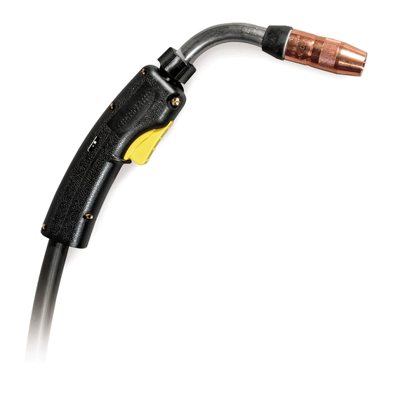
OPERATIONS MANUAL
PipeWorx MIG Gun
Manufactured for Miller Global Pipe Systems
250 Amp
Part Number: 195399
300 Amp
Part Number: 195400
S
D
O
y
!
afety
epenDS
n
Ou
DO NOT INSTALL, OPERATE OR REPAIR
THIS EQUIPMENT WITHOUT READING
THIS OPERATING MANUAL AND THE ARC
WELDING SAFETY PRECAUTIONS ON THE
INSIDE FRONT COVER.
Bernard
Guns are designed and built
™
with safety in mind, but operators must
follow prescribed safety guidelines.
Miller Electric Mfg. Co.
An Illinois Tool Works Company
1635 West Spencer Street
Appleton, WI 54914 USA
International Headquarters-USA
USA Phone: 920-735-4504 Auto-Attended
USA & Canada FAX: 920-735-4125
International FAX: 920-735-4125
European Headquarters - United Kingdom
Phone: 44 (0) 1204-593493
Fax: 44 (0) 1204-598066
MillerWelds.com
© 2015 Bernard Printed in U.S.A. DFB-OPPW-2.2
Advertisement
Table of Contents

Subscribe to Our Youtube Channel
Related Manuals for Bernard 195399


Summary of Contents for Bernard 195399
- Page 1 1635 West Spencer Street Appleton, WI 54914 USA International Headquarters-USA USA Phone: 920-735-4504 Auto-Attended USA & Canada FAX: 920-735-4125 International FAX: 920-735-4125 European Headquarters - United Kingdom Phone: 44 (0) 1204-593493 Fax: 44 (0) 1204-598066 MillerWelds.com © 2015 Bernard Printed in U.S.A. DFB-OPPW-2.2...
-
Page 2: Safety Precautions
SAFETY PRECAUTIONS Some probability of CYLINDERS MAY death or serious injury EXPLODE Some probability of Where compr essed gases are to be used at the job site, special precautions ELECTRIC SHOCK should be used to prevent hazardous situations. death or serious injury CAN KILL Always secure cylinders in an upright position to a fixed support so that they can- Arc welding e... - Page 3 Wear suitable clothing to reduce risk of burns to exposed skin. Wear durable, flame-resistant clothing with closed, opaque weaves. This reduces chance of ‘sun’ burn, contact burns, and accidental ignition of clothing that could occur. Some probability of 3.1.1 Do not wear wet or damp clothing. death or serious injury FUMES &...
-
Page 4: Emf Information
(Metal Inert Gas), MAG (Metal Active Gas), FCAW (Flux Cored Arc hard facing alloys to name a few. With Bernard’s flexibility, many ap- Welding), and MOG (Metal without Gas). plications can be accommodated with field installed options increasing The PipeWorx MIG Gun provides rapid neck interchangeability, typi- performance and maneuverability. - Page 5 page 2 Part II Installation 1. Your gun has been shipped with a specific feeder connector, 8. Safely feed electrode through the gun and approximately 1” neck, and sized for electrode as per the part number indi- (25 mm) beyond head/gas diffuser. cated on its package.
-
Page 6: Section 1. Nozzle
#1. Section 2. Contact Tip Section 4. Neck Bernard has designed Centerfire™ Contact Tips to allow rapid installa- tion and adjustment. A. Removal Grasp lock nut and rotate counterclockwise, rotation will free A. -
Page 7: Section 5. Jump Liner (Optional)
page 4 Part IV Maintenance and Repair (cont.) Section 5. Jump liner (Optional) Section 7. Cable A. Removal A. Inspection Remove nozzle, gas diffuser and neck. Remove used jump Replace the cable assembly if the following conditions are liner from the back end of neck. evident on the exterior of the cable: cuts and/or abrasions in cable jacketing exposing copper stranding, abrupt kinking B. -
Page 8: Section 9. Rigid Strain Relief
page 5 Part IV Maintenance and Repair (cont.) C. Installation Miller Power Pins Insert liner into power pin with cable laying straight. Con- A. Removal tinue until liner lock is fully seated into power pin. A twisting motion may be necessary to seat o-ring (some direct plugs Remove the power pin tip that retains the liner from the may require installation of additional components to secure power pin with the appropriate wrench. - Page 9 6 Part V 250 Amp Gun Exploded Diagram and Parts List Gun Part Number: 195399 PART ITEM NUMBER DESCRIPTION NST-3800B Nozzle TT-035 Contact Tip DS-1 Diffuser 4323R 1840057-2 Q-Nut Insulator, Front QT2-60 Neck (Includes neck and items #5, 7, 8)
- Page 10 page 7 Part V 300 Amp Gun Exploded Diagram and Parts List Gun Part Number: 195400 PART ITEM NUMBER DESCRIPTION NS-5818C Nozzle T-045 Contact Tip DS-1 Diffuser 4323R 1840057-2 Q-Nut Insulator, Front QT2-60 Neck (Includes neck and items #5, #7, #8) 1840057-1 Q-Neck Cover 1840031 Q-Neck Insulator, Rear...
- Page 11 1. Replace with proper size. 2. Electrode eroding contact tip. 2. Inspect and/or change drive rolls. 3. Exceeding duty cycle. 3. Replace with properly rated Bernard MIG Gun. 5. Erratic arc. 1. Worn contact tip. 1. Replace. 2. Buildup inside of liner.
- Page 12 See ‘Maintenance & Repair’ (Section 7). 9. Gun running hot. 1. Exceeding duty cycle. 1. a. Replace with properly rated Bernard gun. b. Decrease parameters to within gun rating. 2. Loose or poor power connection. 2. a. Clean, tighten or replace cable grounding connection.
- Page 13 Notes...
- Page 14 Notes © 2015 Bernard Printed in U.S.A. DFB-OPPW-2.2...
Need help?
Do you have a question about the 195399 and is the answer not in the manual?
Questions and answers