Table of Contents
Advertisement
Available languages
Available languages
Advertisement
Chapters
Table of Contents

Related Manuals for Midland M Zero Plus


Summary of Contents for Midland M Zero Plus
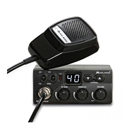
- Page 1 M ZERO PLUS 40CH AM/FM MOBILE TRANSCEIVER...
- Page 3 ITALIANO ENGLISH DEUTSCH ESPAÑOL FRANÇAIS POLSKI ROMÂN...
-
Page 4: Table Of Contents
SOSTITUZIONE DEL FUSIBILE CONNESSIONE DEL MICROFONO MONTAGGIO ANTENNA POSIZIONI COMUNI DI MONTAGGIO DELL’ANTENNA ANTENNA BASE USO DEL RICETRASMETTITORE IMPOSTAZIONE BANDA Po/St SCORRIMENTO RAPIDO DEI CANALI BEEP PRESSIONE TASTI MEMORIZZAZIONE CANALE DI EMERGENZA ALTOPARLANTE SUPPLEMENTARE EXT CARATTERISTICHE TECNICHE M Zero Plus Manuale d’uso... -
Page 5: Principali Funzioni
Per la massima sensibilità del ricevitore è preferibile che il comando sia regolato solo al preciso livello dove il rumore viene eliminato; • Commutatore CH/EMG: permette di commutare immediatamente la radio sul canale di emergenza (il canale di emergenza può essere impostato dall’utente). M Zero Plus Manuale d’uso... -
Page 6: Comandi E Funzioni
Led TX: questa spia si accende quando si preme il tasto PTT del microfono; 13,8V DC CH-EMG: Canale in uso /canale di emergenza. Permette di commutare rapi- damente tra il canale in uso e il canale di emergenza; Commutatore AM/FM: permette di selezionare la modalità di emissione. M Zero Plus Manuale d’uso... - Page 7 27 MHz; Cavo di alimentazione: Inserire il cavo di alimentazione accendisigari da 12V nella relativa presa accendisigari. 12. Altoparlante esterno EXT: presa per la connessione ad un altoparlante esterno (l’innesto dello spinotto esclude automaticamente l’altoparlante interno); M Zero Plus Manuale d’uso...
-
Page 8: Installazione
Controllare che esse siano ben ancorate, in considerazione delle notevoli sollecitazioni e vibrazioni create dal mezzo mobile. M Zero Plus Manuale d’uso... -
Page 9: Sostituzione Del Fusibile
Sostituire il fusibile del cavo di alimentazione con un similare a 2 A (Un fusibile di ricambio è in dotazione). CONNESSIONE DEL MICROFONO La presa del microfono è situata sul davanti dell’apparato. Accertarsi sempre che il connettore sia ben connesso alla presa. M Zero Plus Manuale d’uso... -
Page 10: Montaggio Antenna
è installata posteriormente, diventa direttiva in avanti, cioè i segnali provenienti dalla parte opposta sono meglio ricevuti, così dicasi anche per quelli trasmessi). N.B.: con l’ausilio di un accoppiatore a due vie, l’antenna montata anteriormente può sostituire l’antenna della radio FM. M Zero Plus Manuale d’uso... -
Page 11: Posizioni Comuni Di Montaggio Dell'antenna
Per l’utilizzo del ricetrasmettitore in stazione fissa (base) occorre un alimentatore con una tensione di 12,6V ± 10% capace di erogare una corrente continua di 2A. Si consiglia un’antenna 1/2 onda omnidirezio- nale per comunicazioni a medio e lungo raggio. M Zero Plus Manuale d’uso... -
Page 12: Uso Del Ricetrasmettitore
Per ricevere, rilasciare il pulsante di trasmissione. N.B.: gridare nel microfono non aumenta la portata della trasmissione, in quanto un circuito interno automaticamente commuta la massima modulazione. Si consiglia quindi di usare un tono di voce normale. M Zero Plus Manuale d’uso... -
Page 13: Impostazione Banda Po/St
UP e DOWN; premere nuovamente i due tasti UP e DOWN per circa 5 secondi; il display lampeggerà nuovamente ed indicherà il canale di emergenza memo- rizzato. 10 | M Zero Plus Manuale d’uso... -
Page 14: Altoparlante Supplementare Ext
ALTOPARLANTE SUPPLEMENTARE EXT Inserire un altoparlante con potenza da 3 a 10 Watt nella presa EXT. Il collegamento ad un altoparlante esterno esclude automaticamente quello interno. M Zero Plus Manuale d’uso | 11... -
Page 15: Caratteristiche Tecniche
Dimensioni ................... 110x45x140 mm Peso .........................665 g Le specifiche sono soggette a modifiche senza preavviso. Un dispositivo di sezionamento adatto deve essere previsto nell’impianto elettrico. Tale dispositivo deve disconnettere entrambi i poli simultaneamente. 12 | M Zero Plus Manuale d’uso... - Page 17 MAIN FUNCTIONS CONTROLS AND FUNCTIONS INSTALLATION REPLACING FUSE CONNECTING THE MICROPHONE BASE STATION ANTENNA USING YOUR TRANSCEIVER SELECTION OF Po/St BANDS QUICK SCROLL KEYPAD BEEP EMERGENCY CHANNEL MEMORY EXTERNAL SPEAKER TECHNICAL SPECIFICATIONS M Zero Plus Instruction Guide...
-
Page 18: Main Functions
• CH/EMG: this knob allows to switch immediately to the emergency channel. The emergency channel can be set by the user. M Zero Plus Instruction Guide... -
Page 19: Controls And Functions
TX led: the led lights up when you push the PTT button on the microphone; CH-EMG: Channel in use /Emergency channel. This selector allows to switch quickly between the emergency channel and the channel in use; AM/FM selector: to select AM or FM modulation. M Zero Plus Instruction Guide... - Page 20 10. Antenna coaxial connector SO239: connect here an antenna operating on 27 MHz; Power supply cable: insert the power cable with lighter plug into the vehicle’s cigarette lighter cord. 12. External speaker jack. If you connect an external speaker, the internal one is automatically excluded. M Zero Plus Instruction Guide...
-
Page 21: Installation
When you have determined the best location for mounting, use the mounting bracket as a template to mark mounting holes. Take care when you drill the holes that you do not drill into wiring, trim or other accessories. M Zero Plus Instruction Guide... -
Page 22: Replacing Fuse
Hold the fuse holder and press on the inside, then rotate the holder. CONNECTING THE MICROPHONE Your transceiver has a new microphone connector. This ensures that you won’t acci- dentally pull out or loosen the plug connection when moving the microphone cable out. M Zero Plus Instruction Guide... - Page 23 However, the front position offers a number of advantages. The CB antenna can be easily mounted. It can double as both the CB and the standard auto radio an- M Zero Plus Instruction Guide...
-
Page 24: Base Station Antenna
For example, the 1/2 wave antenna is a high-efficiency radiator with omnidirectional characteristics. It performs as well in most applications as the ground plane does. You can use this type of antenna for medium-long range communications. M Zero Plus Instruction Guide... -
Page 25: Using Your Transceiver
Press the push-to talk button on the microphone and hold it an angle about 5-7 cm from your mouth and speak in a normal voice. To receive, release the push-to-talk button. Be sure the mic plug is firmly connected to the jack. M Zero Plus Instruction Guide... -
Page 26: Selection Of Po/St Bands
UP/DOWN buttons select the new emergency channel; push again UP / DOWN for about 5 seconds; the display will blink again and will indicate the new emergency channel me- mory. 10 | M Zero Plus Instruction Guide... -
Page 27: External Speaker
EXTERNAL SPEAKER Connect a speaker with a power of 3-10 Watt to the EXT jack. When you connect an external speaker to the radio, the internal speaker is auto- matically disconnected. M Zero Plus Instruction Guide | 11... -
Page 28: Technical Specifications
Dimensions ..................110x45x140 mm Weight ........................665 g Specifications are subject to change without notice. A readily accessible disconnect device shall be incorporated in the installation wiring. The disconnect device shall disconnect both poles simultaneously. 12 | M Zero Plus Instruction Guide... - Page 30 HAUPTFUNKTIONEN BEDIENUNG UND FUNKTIONEN INSTALLATION MIKROFONANSCHLUSS MONTAGE DER ANTENNE EMPFEHLUNGEN FESTSTATION BEDIENUNG IHRES FUNKGERÄTES AUSWAHL DER PO / ST BÄNDER QUICK SCROLL TASTENTON NOTRUFKANAL-SPEICHER EXTERNER LAUTSPRECHER TECHNISCHE DATEN M Zero Plus Bedienungsanleitung...
- Page 31 Empfang. Für beste Empfangsempfindlichkeit, die Rauschsperre nur so hoch einstellen, dass die Hintergrundgeräusche gerade ausgeblendet werden; • CH/EMG: Mit diesem Schalter kann direkt auf den Notrufkanal umgeschaltet werden. Der Notrufkanal kann durch den Benutzer eingestellt werden. M Zero Plus Bedienungsanleitung...
- Page 32 TX LED: Die LED leuchtet, wenn die PTT-Taste am Mikrofon gedrückt wird; CH-EMG: Eingestellter Kanal/Notrufkanal. Dieser Schalter ermöglicht es, schnell zwischen den Notrufkanal und dem eingestellten Kanal zu wechseln; AM/FM Schalter: Wählen Sie zwischen AM und FM Modulation. M Zero Plus Bedienungsanleitung...
- Page 33 10. Antennenbuchse SO239: Schließen sie hier eine Antenne an, die auf 27 MHz abgestimmt ist; Stromversorgungskabel: stecken Sie das Stromkabel mit dem Stecker in die Zi- garettenanzünderbuchse in Ihrem Auto Anschluss für externen Lautsprecher: Bei Anschluss eines externen Lautspre- cher, wird der interne automatisch ausgeschaltet; M Zero Plus Bedienungsanleitung...
- Page 34 Sonneneinstrahlung ausgesetzt sein, da es sich sonst zu stark erwärmen könnte! Aus dem selben Grund darf es nicht in der Nähe der Austrittsöffnungen für die Heizluft montiert werden. Überlicherweise wird das Funkgerät unter dem Armaturenbrett montiert. M Zero Plus Bedienungsanleitung...
- Page 35 Stromversorgung und der Antenne sowie eines eventuellen externen Lautspre- chers fixieren Sie das Funkgerät in der Mobilhalterung: Ziehen Sie die seitlichen Rändelschrauben in der gewünschten Position fest. Ihr M ZERO PLUS wird mit 12,6+/-10% Gleichspannung betrieben. Stecken Sie den Stecker der Versorgungsleitung in die Zigarettenanzünder-Buchse des Fahrzeugs.
- Page 36 MONTAGE DER ANTENNE Die Antenne stellt das wichtigste Element einer Funkstation dar, und entscheidet im Wesentlichen über die Reichweite. Der Antennenanschluss Ihres M Zero Plus weist eine Impedanz von 50 Ohm auf. Sie müssen eine CB-Mobilantenne mit der- selben Impedanz verwenden und diese über ein Koaxialkabel (ebenfalls mit 50 Ohm Impedanz) mit der Antennenbuchse des Funkgerätes verbinden.
- Page 37 Wenn Sie Ihr Funkgerät als Feststation einsetzen wollen, benöti- gen Sie ein Netzgerät, das an einer geregelten Festspannung von 12,6 V ± 10% einen Strom von mindestens 2 Ampere abgeben kann. Als Außenantenne empfehlen wir eine 1/2 Lambda An- tenne. M Zero Plus Bedienungsanleitung...
- Page 38 Ihr Funkgerät befindet sich solange auf Sendung, bis Sie die Sendetaste wie- der loslassen. Notiz: Schreien in das Mikrofon erhöht nicht die Reichweite. Ein integrierter Schaltkreis regelt die max. Wiedergabelautstärke. Es wird empfohlen mit normaler Lautstärke in das Mikrofon zu sprechen. M Zero Plus Bedienungsanleitung...
- Page 39 Anzeige hört auf zu blinken; mit den UP/DOWN-Tasten den neuen Notrufkanal wählen; nochmals die UP- und DOWN-Tasten gleichzeitig für etwa 5 Sekunden drü- cken; die Anzeige blinkt wieder und der neue Notrufkanal wird angezeigt. 10 | M Zero Plus Bedienungsanleitung...
- Page 40 EXTERNER LAUTSPRECHER Schließen Sie einen Lautsprecher mit einer Belastbarkeit von 3 bis 10 Watt an die EXT-Buchse an. Wenn Sie einen externen Lautsprecher an das Gerät anschließen, wird der interne Lautsprecher automatisch abgeschaltet. M Zero Plus Bedienungsanleitung | 11...
-
Page 41: Technische Daten
Frequenztoleranz ....................0.002% Betriebsspannung ..................12,6 V ± 10% Stromaufnahme ......................2 A Antennenimpedanz ...................50 Ohm Abmessungen ..................110x45x140 mm Gewicht ........................665 g Abweichungen von den Technischen Daten im Zuge der Weiterentwicklung bleiben vorbehal- ten. 12 | M Zero Plus Bedienungsanleitung... - Page 43 Posiciones comunes de montaje de la antena ANTENA PARA ESTACIÓN BASE USO DEL TRANSCEPTOR AJUSTE BANDA Po/St EXPLORACIÓN RÁPIDA SONIDO TECLADO MEMORIZACIÓN CANAL DE EMERGENCIA ALTAVOZ SUPLETORIO EXT CONSEJOS PARA USAR SU CB SERVICIO Y MANTENIMIENTO CARACTERÍSTICAS TÉCNICAS M Zero Plus Manual de Instrucciones...
- Page 44 • Conmutador CH/EMG: permite conmutar inmediatamente al canal de emer- gencia (el canal de emergencia puede fijarlo el usuario); M Zero Plus Manual de Instrucciones...
- Page 45 Led TX: se enciende cuando la radio transmite (se pulsa el PTT del micrófono); CH-EMG: Canal en uso / canal de emergencia. Permite conmutar rápida- mente entre el canal en uso y el de emergencia; Conmutador AM/FM: para seleccionar la modulación AM o FM; M Zero Plus Manual de Instrucciones...
- Page 46 Cable de alimentación: use el cable de mechero incluido y enchúfelo a la toma de 12Vcc del vehículo.; 12. Altavoz exterior EXT: toma para conectar un altavoz exterior (si se conecta, se desactiva el altavoz del equipo); M Zero Plus Manual de Instrucciones...
- Page 47 Cuando haga los agujeros, tenga cuidado de no taladrar el cableado u otros accesorios. Instale la unidad mediante tornillos, arandelas y tuercas o tornillos de rosca. M Zero Plus Manual de Instrucciones...
- Page 48 Sustituya el fusible del cable de alimentación con uno similar de 2 amperios (hay un fusible de recambio en dotación). CONEXIÓN DEL MICRÓFONO La toma del micrófono está situada en la parte frontal del equipo. Asegúrese siem- pre de que el conector esté bien conectado a dicha toma. M Zero Plus Manual de Instrucciones...
- Page 49 Nota: con la ayuda de un acoplador de dos vías, la antena indicada anteriormente puede sustituir a la antena de la radio FM. M Zero Plus Manual de Instrucciones...
- Page 50 Puede utilizar el equipo como una unidad de estación base, junto con una fuente de alimentación de 12,6 Vcc ± 10%/2A (continuos). Re- comendamos una antena de 1/2 onda que emite con alta eficiencia y omnidireccionalmente para comunicaciones a media y larga distan- cia. M Zero Plus Manual de Instrucciones...
- Page 51 Pulse el botón PTT (pulsar-para-hablar) del micrófono y mantenga éste a una distancia de unos 5-8 cm de su boca y hable frente a él en un tono de voz normal. Para recibir, libere el botón PTT. M Zero Plus Manual de Instrucciones...
- Page 52 Mantenga pulsada la tecla UP y encienda la radio; Pulse la tecla UP o DOWN para activar o desactivar el beep; El display mostrará “ON” cuando el beep esté activo u “OF” cuando esté desactivado. 10 | M Zero Plus Manual de Instrucciones...
- Page 53 El display parpadeará nuevamente e indicará el canal de emergencia memo- rizado. ALTAVOZ SUPLETORIO EXT Conecte un altavoz con potencia de 3 a 10W en la toma EXT. La conexión de un altavoz externo inhabilita el altavoz de la radio. M Zero Plus Manual de Instrucciones | 11...
- Page 54 • Ayude a los usuarios que requieran información sobre direcciones, condiciones de las carreteras u otros datos. • Sea cortés. Trate a los demás como desearía que le tratasen a usted. 12 | M Zero Plus Manual de Instrucciones...
- Page 55 ADVERTENCIA: No abra el transceptor para efectuar ajustes internos. Cualquier aju- ste interno sólo puede ser efectuado por personal debidamente cualificado. M Zero Plus Manual de Instrucciones | 13...
- Page 56 Dimensiones ..................110x45x140 mm Peso .........................665 g Todas las especificaciones están sujetas a cambio sin previo aviso. El cable de alimentación incorpora un dispositivo de fácil desconexión. Dicho dispositivo desco- necta los dos polos simultáneamente. 14 | M Zero Plus Manual de Instrucciones...
- Page 58 SUBSTITUTION DU FUSIBLE CONNEXION DU MICROPHONE MONTAGE DE L’ANTENNE POSITIONS COMMUNES DE MONTAGE DE L’ANTENNE ANTENNE BASE USAGE DE L’EMETTEUR-RECEPTEUR REGLAGE BANDE Po/St GLISSEMENT RAPIDE DES CANAUX BEEP TOUCHES MEMORISATION DU CANAL D’URGENCE CARACTERISTIQUES TECHNIQUES M Zero Plus Guide de utilisation...
- Page 59 • Sélecteur SQUELCH: pour éliminer le bruit de fond en réception. Stopper la rotation à l’endroit exact ou le bruit audible dans le haut-parleur disparait. • CH/EMG: permet la commutation immédiate sur le canal d’urgence (peut être réglé par l’utilisateur). M Zero Plus Guide de utilisation...
- Page 60 Voyant TX: le led s’allume quand vous appuyez sur le PTT du microphone; CH-EMG: Canal actif /canal d’urgence. Cette touche permet de changer ra- pidement entre le canal actif et le canal d’urgence; Commutateur AM/FM: pour sélectionner la modulation AM ou FM. M Zero Plus Guide de utilisation...
- Page 61 10. Connecteur coaxial d’antenne SO239: connectez une antenne qui fonction- ne sur 27MHz; Câble d’alimentation: raccordez le connecteur allume-cigare du cordon d’ali- mentation au connecteur allume-cigare de votre véhicule; Haut-parleur extérieur EXT: raccordement pour un haut-parleur extérieur (ceci exclut automatiquement l’haut-parleur intérieur). M Zero Plus Guide de utilisation...
- Page 62 Contrôlez que les vis soient bien fixées, en tenant compte des nombreuses contraintes et vibrations générées dans le moyen mobile. M Zero Plus Guide de utilisation...
- Page 63 Substituez le fusible du câble d’alimentation avec un similaire à 2 A (Un fusible de rechange est fourni). CONNEXION DU MICROPHONE La prise du microphone est placée sur le devant de l’appareil. Vous devez toujours vérifier que le connecteur soit bien connecté à la prise. M Zero Plus Guide de utilisation...
- Page 64 (exemple: si l’antenne est installée dans la partie postérieure, elle devient directive en avant, c’est-à-dire que les signaux provenant de la part opposée sont mieux reçus, c’est la même chose pour les signal transmis). M Zero Plus Guide de utilisation...
- Page 65 12,6 V ± 10% capable de débiter un courant continu de 2A. Nous vous conseillons une antenne 1/2 onde omnidirectionnelle pour les communications à moyen et long rayon. M Zero Plus Guide de utilisation...
- Page 66 Pour recevoir, relâchez le bouton d’émission. N.B.: crier dans le microphone n’augmente pas la charge de l’émission, puisqu’un cir- cuit intérieur commute automatiquement la modulation maximale. Nous conseillons d’utiliser un ton de voix normal. M Zero Plus Guide de utilisation...
- Page 67 REGLAGE BANDE Po/St Allumez M ZERO PLUS en maintenant appuyé les touches UP/DOWN; Appuyez UP ou DOWN pour sélectionner la bande désirée: Po = Pologne (40 Ch AM/FM - 26.960/27.400) - St =Europe (40 CH AM/ FM - 26.965/27.405) Appuyez PTT pour sortir de la sélection.
- Page 68 Dimension ..................1104x45x140 mm Poids ........................665 kg Toutes ces caractéristiques peuvent être modifié sans préavis. Il est conseillé de mettre un interrupteur dans le câblage d’alimentation du poste. L’interrupteur doit couper les deux pôles simultanément. M Zero Plus Guide de utilisation | 11...
- Page 69 PODSTAWOWE FUNKCJE ELEMENTY STEROWANIA INSTALACJA WYMIANA BEZPIECZNIKA PODŁĄCZENIE MIKROFONU ANTENA ANTENA BAZOWA OBSŁUGA RADIA Wskazówki dla użytkownika Midlanda M0 SZYBKA ZMIANA KANAŁÓW DŹWIĘK PRZYCISKÓW ZAPAMIĘTANIE KANAŁU RATUNKOWEGO ZEWNĘTRZNY GŁOŚNIK DANE TECHNICZNE M Zero Plus Instrukcja obsługi...
- Page 70 Dalsze przekręcanie spowoduje że słabe sygnały od dalszych korespondentów nie będą odbierane. • CH/EMG: Szybki dostęp do kanału zwyczajowo nazywanego ratunkowym. Można samemu wybrać kanał, który będzie dostępny za pomocą tego przełącznika M Zero Plus Instrukcja obsługi...
- Page 71 Wyświetlacz: Pokazuje numer aktualnie używanego kanału. Dioda TX: Sygnalizuje nadawanie w trakcie trzymania wciśniętego przycisku PTT w mikrofonie. CH-EMG: Przełącznik szybkiego dostępu do kanału ratunkowego i powrotu do aktualnie używanego. Przełącznik AM/FM: do wyboru modulacji AM lub FM M Zero Plus Instrukcja obsługi...
- Page 72 Kabel zasilający: Przewód z wtykiem do gniazda zapalniczki o napięciu prądu stałego nie wyższym niż 13,8V. Gniazdo zewnętrznego głośnika: Jeżeli słyszalność jest niezadowalająca można podłączyć zewnętrzny głośnik. Wsunięcie wtyku powoduje automatyczne odłączenie wbudowanego, wewnętrznego głośnika. M Zero Plus Instrukcja obsługi...
- Page 73 Umieść radio pomiędzy ramionami wspornika i wstępnie przykręć boczne śruby mocujące. Ustaw radiotelefon pod najbardziej wygodnym dla ciebie kątem i dokręć ostatecznie śruby Zamontuj wieszak mikrofonu niedaleko radia lub na jego bocznej lewej ściance. M Zero Plus Instrukcja obsługi...
- Page 74 Lutując wtyk do zapalniczki pamiętaj, że w większości samochodów ,,+” występuje w środkowej części gniazda, a ,,– ” na zewnętrznej. Gdy poziom dźwięku nie jest satysfakcjonujący możesz podłączyć zewnętrzny głośnik do gniazda EXT-SPKR. M Zero Plus Instrukcja obsługi...
- Page 75 Mocowanie na przednim błotniku Antena ma lekko kierunkową charakterystykę pracy z uprzywilejowanym kierunki- em tylnym przeciwnym do mocowania anteny. Ta lokalizacja oferuje łatwy dostęp M Zero Plus Instrukcja obsługi...
- Page 76 Jedną z najbardziej uniwersal- nych anten stosowanych do łączności na średnich dystansach jest pełnowymiarowa antena o długości ½ fali Ma wysokowydajny pro- miennik o dookólnej charakterystyce i większości wypadków działa tak jak anteny typu ground plane. M Zero Plus Instrukcja obsługi...
- Page 77 Blokada w pewnym zakresie będzie podążać za fluktuacjami mocy sygnału i szumów poprawiając warunki odsłuchu. Nadawanie: Wybierz kanał i modulacji (AM lub FM). Wciśnij i trzymaj cały czas wciśnięty przycisk nadawania PTT mówiąc normal- M Zero Plus Instrukcja obsługi...
- Page 78 19. Jeżeli chciałbyś go zmienić postępuj zastosuj poniższą procedurę: Ustaw przełącznik szybkiego dostępu do kanału ratunkowego CH/EMG w pozycję EMG. Na wyświetlaczu będzie migał numer kanału, który aktualnie jest kanałem ra- tunkowym. 10 | M Zero Plus Instrukcja obsługi...
- Page 79 Wyświetlacz pokaże migający numer nowo wybranego kanału. ZEWNĘTRZNY GŁOŚNIK Do gniazda na tylnym panelu można podłączyć zewnętrzny głośnik o mocy 3-10W. Podłączenie spowoduje automatyczne wyciszenie głośnika wewnętrznego, wbudo- wanego w radio. M Zero Plus Instrukcja obsługi | 11...
-
Page 80: Dane Techniczne
Zasilanie ....................12,6 V ±10% max Maksymalny pobór prądu ...................2A Wymiary ....................110x45x140 mm Waga ........................665 g Producent zastrzega możliwość wprowadzenia zmian. Łatwo dostępny wyłącznik odcinający prąd z obydwu biegunów powinien być zain- stalowany na torze zasilającym. 12 | M Zero Plus Instrukcja obsługi... - Page 82 FUNCTII PRINCIPALE REGLAJE SI FUNCTII INSTALARE INLOCUIREA SIGURANTEI CONECTAREA MICROFONULUI ANTENA INSTRUCTIUNI DE UTILIZARE SELECTARE BANDA SELECTARE RAPIDA CANAL SUNET TASTE MEMORAREA UNUI CANAL DE URGENTA DIFUZOR EXTERN SPECIFICATII TEHNICE M Zero Plus Manual de utilizare...
- Page 83 • CH/EMG: acest comutator va permite accesul imediat la canalul de urgenta. Canalul de urgenta poate fi setat de utilizator. M Zero Plus Manual de utilizare...
- Page 84 Ecran LCD: afiseaza numarul canalului utilizat; LED TX: acesta se aprinde cand apasati butonul PTT de pe microfon; Comutator CH-EMG: comutati intre canalul utilizat si cel de urgenta; Comutator AM/FM: selectati modulatia dorita: AM sau FM. M Zero Plus Manual de utilizare...
- Page 85 27 MHz; Cablu alimentare: introduceti mufa din capatul cablulului de alimentare in mufa de bricheta a autovehiculului; 12. Mufa pentru difuzor extern: daca utilizati un difuzor extern cel intern va fi automat dezactivat. M Zero Plus Manual de utilizare...
- Page 86 Aveti rabdare, si planuiti instalarea statiei cu atentie. Cand determinati pozitia optima pentru montaj, utilizati suportul din colet pentru a marca punctele in care trebuie efectuate gaurile. Aveti grija cand efectuati gaurile sa nu atingeti cablaje sau alte accesorii ale autovehiculului. M Zero Plus Manual de utilizare...
- Page 87 Tineti suportul sigurantei in mana si impingeti capetele spre interior apoi rotiti pentru a elibera siguranta. CONECTAREA MICROFONULUI Statia are un nou conector pentru microfon ce elimina posibilitatea smulgerii accidentale sau decuplarea atunci cand miscati microfonul. M Zero Plus Manual de utilizare...
- Page 88 Totusi, montarea pe capota va ofera avantajul montarii si demontarii usoare a antenei. Montare pe portbagaj: Directia radiatiilor va fi putin mai mare spre fata masinii, in directia opusa montarii antenei. In aceasta pozitie va recomandam utilizarea unei antene putin mai lungi. M Zero Plus Manual de utilizare...
- Page 89 Pentru utilizarea dispozitivului ca statie fixa (de baza) aveti nevoie de o sursa de alimentare 12,6 Vdc ± 10%, ce suporta un consum continuu de 2A. Recomandam utilizarea unei antene omnidirectionale de 1/2 lungime de unda, pentru a comunica pe distante medii si lungi. M Zero Plus Manual de utilizare...
- Page 90 Pentru a receptiona eliberati butonul PTT. NOTA: tipand in microfon nu va creste puterea de emisie sau semnalul dv. Un circuit intern seteaza automat semnalul microfonului la o modulatie maxima, astfel ca tipatul nu va aduce nici un avantaj. M Zero Plus Manual de utilizare...
- Page 91 Utilizati butoanele Sus/Jos pentru a selecta canalul de urgenta dorit; Apasati din nou simultan butoanele Sus/Jos timp de 5 sec.; Numarul de pe ecran va clipi din nou si va indica noul canal de urgenta. 10 | M Zero Plus Manual de utilizare...
- Page 92 DIFUZOR EXTERN Puteti conecta la statie un difuzor extern de 3-10 W la iesirea EXT. Atunci cand utilizati un difuzor extern cel intern va fi dezactivat automat. M Zero Plus Manual de utilizare | 11...
- Page 93 Toleranta frecventa ................. mai buna de 0.002% Impedanta antena ....................50 Ohm Tensiune de alimentare ............... 12,6 V ± 10%max Consum maxim ......................2A Dimensiuni .................... 110x45x140 mm Greutate ........................665 g Specificatiile se pot modifica fara preaviz. 12 | M Zero Plus Manual de utilizare...
- Page 94 • INFORMAZIONE AGLI UTENTI: Ai sensi dell’art. 13 del decreto legislativo 25 luglio 2005, n.151 “Attuazione delle Direttive 2002/95/CE, 2002/96/CE e 2003/108/CE, relative alla riduzione dell’uso di sostanze pericolose nelle apparecchiature elettriche ed elettroniche, nonché allo smaltimento dei rifiuti”. Il simbolo del cassonetto barra- to riportato sull’apparecchiatura indica che il prodotto alla fine della propria vita utile deve essere raccolto separatamente dagli altri rifiuti.
- Page 95 Italia - Restrizioni all’uso - In conformità al Piano Nazionale di ripartizione delle Frequenze, pubblicato sulla G.U. n. 169 -Supplemento Ordinario 146 - del 20 luglio 2002 - nota 49G -, per lo standard in AM occorre utilizzare un sistema radiante che abbia il guadagno comples- sivo non superiore a -6 dB (es.: con antenna PC8 con cavo originale).
- Page 96 RTTE I / RSM 1999, transposta para a legislação nacio- Cte International Srl dichiara che il pro- nal pelo Decreto-Lei n.º 192/2000, de dotto è conforme ai requisiti essenziali e 18 de Agosto. A Declaração de Confor- alle disposizioni della Direttiva 1999/5/ midade está...
- Page 97 www.midlandeurope.com съответствие с основните изисквания и съответните модификации на CTE International patvirtina, kad Директива 1999/5/EC. Декларацията šis modelis atitinka visus esmi- за съвместимост е налична на сайта: nius Direktyvos 1999/5/EC bei su www.midlandeurope.com ja susijusių dokumentų reikalavinus. CTE INTERNATIONAL Srl erklærer at Atitikties deklaracija yra pateikiama produktet er i overensstemmelse med internetinėje svetainėje www.midlandeu-...
- Page 98 ALAN COMMUNICATIONS, S.A. Via. R.Sevardi 7 C/Cobalt, 48 - 08940 Cornellá de Llobregat 42124 Mancasale Reggio Emilia Italia España - www.midland.es www.midlandeurope.com El uso de este equipo puede estar sujeto a la In Italia l’uso è soggetto a dichiarazione, artt.
Need help?
Do you have a question about the M Zero Plus and is the answer not in the manual?
Questions and answers