Table of Contents
Advertisement
Available languages
Available languages
Quick Links
BRUCIATORE DI GASOLIO A DUE FIAMME
LIGHT OIL BURNERS
BRULEUR FIOUL DOMESTIQUE A DEUX FLAMMES
ZWEIFLAMMIGE ÖLBRENNER
QUEMADORES PARA GASÓLEO CON DOS LLAMAS
∫∞À™∆∏P∂™ ¶∂∆P∂§∞I√À ª∂ ¢À√ º§√°∂™
ECO 50/2 - ECO 70/2
MANUALE DI
INSTALLATION AND
NOTICE
INSTALLATIONS-
MANUAL PARA LA
ΕΓΧΕΙΡΙΔΙΟ
INSTALLAZIONE E
MAINTENANCE
D'INSTALLATION
UND
INSTALACIÓN Y EL
ΕΓΚΑΤΑΣΤΑΣΗΣ
MANUTENZIONE
MANUAL
ET D'ENTRETIEN
WARTUNGSANLEITUNG
MANTENIMIENTO
ΚΑΙ ΣΥΝΤΗΡΗΣΗΣ
Advertisement
Chapters
Table of Contents

Related Manuals for Lamborghini Caloreclima ECO 50/2


Summary of Contents for Lamborghini Caloreclima ECO 50/2
- Page 1 BRUCIATORE DI GASOLIO A DUE FIAMME LIGHT OIL BURNERS BRULEUR FIOUL DOMESTIQUE A DEUX FLAMMES ZWEIFLAMMIGE ÖLBRENNER QUEMADORES PARA GASÓLEO CON DOS LLAMAS ∫∞À™∆∏P∂™ ¶∂∆P∂§∞I√À ª∂ ¢À√ º§√°∂™ ECO 50/2 - ECO 70/2 MANUALE DI INSTALLATION AND NOTICE INSTALLATIONS- MANUAL PARA LA ΕΓΧΕΙΡΙΔΙΟ...
- Page 3 ITALIANO Leggere attentamente le istruzioni ed avvertenze contenute sul presente libretto in quanto forniscono importanti indicazioni riguardanti la sicurezza d’installazione, d’uso e di manutenzione. Conservare con cura questo libretto per ogni ulteriore consultazione. L’installazione deve essere effetuata da per- sonale qualificato che sarà responsabile del rispetto delle norme di sicurezza vigenti.
-
Page 4: Table Of Contents
... per l’ottima scelta. La ringraziamo per la preferenza accordata ai nostri prodotti. LAMBORGHINI CALORECLIMA è un'Azienda quotidianamente impegnata nella ricerca di soluzioni tecniche inno- vative, capaci di soddisfare ogni esigenza. La presenza costante dei nostri prodotti sul mercato italiano ed interna- zionale, è... -
Page 5: Norme Generali Pag
NORME GENERALI • Il presente libretto costituisce parte integrante ed essenziale del prodotto e dovrà essere consegnato all’installatore. Leggere attentamente le avvertenze contenute nel presente libretto in quanto forniscono importanti indicazioni riguardanti la sicurezza d’installazione, d’uso e manutenzione. Conservare con cura questo libretto per ogni ulteriore consultazione. L’installazione del bruciatore deve essere effettuata in ottemperanza alle norme vigenti, secondo le istruzioni del costruttore e da personale qualificato. -
Page 6: Descrizione
I bruciatori sono ad ispezionabilità totale, rendendo facili e rapide le ope- razioni di controllo e manutenzione. Tipi ECO 50/2 e ECO 70/2 a due ugelli, con avviamento a portata ridotta e funzionamento “alta/bassa fiamma”. -
Page 7: Dimensioni Mm
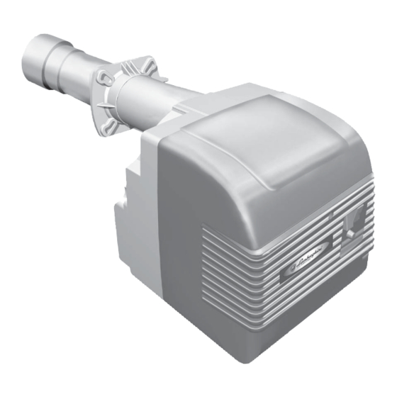
DIMENSIONI mm Ø ØL Modello ØG Ø 1040 121÷160 3/8” ECO 50/2 ECO 70/2 1080 160÷200 3/8” COMPONENTI PRINCIPALI Legenda 1 Cofano 6 Motore 11 Piastra componenti 7 Ventola 12 Fotoresistenza 2 Apparecchiatura 3 Corpo bruciatore 8 Pompa 13 Valvola elettromagnetica... -
Page 8: Caratteristiche Tecniche
CARATTERISTICHE TECNICHE DESCRIZIONE ECO 50/2 ECO 70/2 min. max. Potenza termica min. 152.300 169.000 kcal/h max. 503.200 667.600 kcal/h min. (15) - 21,4 (16,6) - 27 kg/h Consumo combustibile max. 49,3 65,4 kg/h Pompa combustibile Combustibile p.c.i. 10200 kcal/kg 1,50°E (6cst) a 20°C... -
Page 9: Montaggio Alla Caldaia
MONTAGGIO ALLA CALDAIA Fissare la flangia 2 alla caldaia con n° 4 viti 3 interponendo la guarnizione isolante 4 e l’eventuale corda isolante 5. Infilare il bruciatore nella flangia in modo che il boccaglio penetri nella camera di combustione secondo le indicazioni del costruttore della caldaia. -
Page 10: Collegamenti Elettrici
COLLEGAMENTI ELETTRICI - 10... -
Page 11: Alimentazione Gasolio
I collegamenti da effettuare a cura dell’installatore sono: - linea di alimentazione - linea termostatica - eventuale lampada di blocco - eventuale contaore - eventuale termostato modulazione fiamma (togliere il cavo che ponticella) N.B.: È necessario osservare scrupolosamente la buona norma che indica il collegamento di massimo due cavi per morsetto. -
Page 12: Scelta Ugello
SCELTA UGELLO La scelta va fatta in relazione alla potenza del focolare della caldaia, tenendo presente che il gasolio ha un potere calo- rifico (P.C.I.) di 10200 kcal/kg. La tabella indica la portata teorica o consumo, in kg/h e in kW, di gasolio in funzione della grandezza dell’ugello (GPH) e della pressione della pompa (in bar). -
Page 13: Posizionamento Elettrodi-Deflettore
POSIZIONAMENTO ELETTRODI - DEFLETTORE Dopo avere montato l’ugello (o gli ugelli), verificare il corretto posizionamento di elettrodi e deflettore, secondo le quote riportate (mm). È opportuno esguire una verifica delle quote dopo ogni intervento sulla testa. + 0,5 CICLO FUNZIONAMENTO Termostato amb.-caldaia Motore Trasformatore... -
Page 14: Diagnosi Della Causa Del Difetto Lmo 44
DIAGNOSI DELLA CAUSA DEL DIFETTO LMO 44 Dopo la messa in blocco la lampada rossa di indicazione di difetto LR rimane costantemente accesa. In questa condizione, può essere attivata la diagnosi visiva della causa di difetto secondo la tabella codici errore premendo il pulsante di sblocco PS per oltre 3 secondi. -
Page 15: Regolazione Testa
REGOLAZIONE TESTA Agendo sulla vite A si modifica la posi- zione della linea ugello/deflettore rispet- ECO 50/2 to al boccaglio, variando, di conseguen- ECO 70/2 za, la sezione di passaggio dell’aria. REGOLAZIONI ARIA DI COMBUSTIONE La serranda aria è azionata dal motoriduttore. -
Page 16: Messa In Funzione
MESSA IN FUNZIONE 1) OPERAZIONI PRELIMINARI - montare il manometro ed il vuotometro sulla pompa (togliere dopo la messa a punto). - aprire le saracinesche lungo la tubazione del gasolio. - chiudere la linea dei termostati (caldaia/ambiente) - dare corrente dall’interrutore generale - porre in posizione di marcia l’interrutore - sbloccare l’apparecchiatura (spingendo il pulsante rosso) 2) AVVIAMENTO... -
Page 17: Regolazione Pressione Pompa
REGOLAZIONE PRESSIONE POMPA La pompa è pretarata a 12 bar. Per il controllo della pressione servirsi di un manometro a bagno d’olio. La pressione può essere normalmente regolata fra 11 e 15 bar. Prex. bar m H O 1 - Aspirazione 2 - Ritorno 3 - Ugello 4 - Regolazione pressione... -
Page 18: Manutenzione
MANUTENZIONE Tutte le operazioni devono essere eseguite dopo aver tolto corrente. Togliendo il cofano é possibile effettuare la pulizia della fotoresisten- za, ispezionare il motore, la valvola elettroma- gnetica, il trasformatore ed il servocomando serranda aria. Per effettuare la pulizia/ispezione ugello - elet- trodi, normalmente si estrae il gruppo testata attraverso la rimozione della piastra superiore. -
Page 19: Elettrodi Ugello
ELETTRODI - UGELLO Dopo aver tolto il cofano, sfilare i cavi di alta tensione dal lato trasformatore, sfilare la fotoresistenza, svitare i raccordi che collegano i tubi del gasolio alle linee degli ugelli, allentare le viti della piastra superiore ed estrarla con il gruppo flangia- ugello-deflettore-elettrodi. -
Page 20: Irregolarita' Di Funzionamento
IRREGOLARITÀ DI FUNZIONAMENTO DIFETTO CAUSA RIMEDIO IL BRUCIATORE NON PARTE E NON a) Mancanza di energia elettrica. a) Controllare i fusibili. C’È SEGNALE DI BLOCCO. b) Non arriva il combustibile b) Controllare i termostati (ambiente, al bruciatore. caldaia e sicurezza). c) Controllare la linea di alimentazione. - Page 21 - 21...
- Page 22 ... on your excellent choice. Thank you for choosing our products. LAMBORGHINI CALORECLIMA is daily committed to seeking innovative technical solutions to satisfy every need. Constant presence of our products on the Italian and international markets is assured by a widespread network of Agents and Dealers assisted by “LAMBORGHINI SERVICE”...
-
Page 23: General Instructions
GENERAL INSTRUCTIONS • This booklet constitutes an integral and essential part of the product and should be supplied to the installer. Read the instructions contained in this booklet carefully as they give important directions regarding the safety of installation, use and maintenance. - Page 24 The burners may be inspected completely, which makes for rapid and easy control and maintenance. Types ECO 50/2 and ECO 70/2 with double choke, with reduced output start-up and high/low flame function. - 24...
- Page 25 DIMENSIONS mm Ø ØL Model ØG Ø 1040 121÷160 3/8” ECO 50/2 ECO 70/2 1080 160÷200 3/8” MAIN COMPONENTS Legend 1 Cover 6 Motor 11 Components plate 2 Control box 7 Fan 12 Photo resistance 3 Burner body 8 Pump...
- Page 26 TECHNICAL FEATURES DESCRIPTION ECO 50/2 ECO 70/2 min. max. Output min. 152.300 169.000 kcal/h max. 503.200 667.600 kcal/h min. (15) - 21,4 (16,6) - 27 kg/h Fuel consumption max. 49,3 65,4 kg/h Pressure calibration of the fuel pump Combustibile p.c.i. 10200 kcal/kg 1,50°E (6cst) a 20°C...
- Page 27 ASSEMBLY WITH THE FURNACE Attach the flange 2 to the furnace with n° 4 screws (3) through the sealing gasket (4) and any seals (5). Insert the burner in the flange so that the nozzle enters the combustion chamber as indicated by the manufacturer of the furnace. Tighten the screw (1) to lock the burner in place.
- Page 28 WIRING DIAGRAMS - 28...
- Page 29 The connections to be made by the installer are as follows: - Electrical supply line - Thermostat line - Warning light (optional) - Timer (optional) - Flame control thermostat (optional) Eliminate any cable bridges N.B.: It is necessary to observe scrupulously normal working practices that indicate attachment of no more than two cables per terminal.
- Page 30 CHOKE SELECTION The selection is made in relation to the effective output of the furnace, considering that light oil has a calorific power (P.C.I.) of 10,200 kcal/kg. The table indicates the theoretic output or consumption, in kg/h and in kW, of light oil in relation to the size of the choke (GPH) and of the pump pressure (in bar).
- Page 31 ELECTRODE-DEFLECTOR POSITIONING After mounting the choke (or chokes), check the correct position of the electrodes and deflector, following the listed speci- fications (mm). It is advisable to check the specifications after each intervention on the combustion head. + 0,5 OPERATION CYCLE Thermostat room temperature - furnace Motor Transformer...
- Page 32 DIAGNOSIS OF CAUSE OF FAULT LMO44 After lock-out, the red fault signal lamp LR remains steady on. In that condition, the visual diagnosis of the cause of fault according to the error code table can be activated by pressing the lock-out reset button PS for more than 3 seconds. Pressing the reset button again for at least 3 seconds, the interface diagnosis will be activated.
- Page 33 COMBUSTION HEAD ADJUSTMENT Adjusting screw A modifies the position of the line choke/deflector with regards ECO 50/2 to the flow nozzle, thereby varying the ECO 70/2 opening of the air intake. AIR INTAKE ADJUSTMENT The motor reducer controls the air intake valve. Adjustment of the open/close position of the 1° flame / max. opening is controlled by turning the cam anti-clockwise to open the butterfly valve and clockwise to close.
- Page 34 STARTING PROCEDURES 1) Preliminary operations - Mount the pressure gauge and the vacuum gauge on the pump (remove after tune up). - Open the fuel line valve. - Close the thermostat lines (furnace/room temperature) - Attach electricity to the main switch. - Switch to the on position.
- Page 35 PUMP PRESSURE ADJUSTMENT The pump is pre-set at 12 bar. To control the pressure, use the oil pressure gauge. Normally, the pressure is set between 11 and 15 bar. Prex. bar m H O 1 - Suction feed 2 - Return 3 - Choke 4 - Pressure control N.B.
- Page 36 MAINTENANCE All operations should be performed with the electrical supply disconnected. After removing the casing, it is possible to clean the photo resistance, inspect the motor, the electroma- gnetic valve, the transformer and the air intake control. To reach the fan and butterfly valve, the over-head plate and component mount must be removed.
- Page 37 ELECTRODES – CHOKE After removing the cover, detach the high-tension cables from the transformer side, remove the photo resistance, unscrew the connector that hooks the fuel line to the choke, loosen the screws of the overhead plate and remove it with the flange- choke-deflector-electrode assembly.
- Page 38 FAULT-FINDING CHART PROBLEM CAUSE SOLUTION THE BURNER DOES NOT START a) There is no electricity. a) Check the fuses AND THERE IS NO SIGNAL FROM b) Fuel is not arriving to the burner. b) Check the thermostats (Room tem THE WARNING LIGHT. perature, Furnace and safety).
- Page 39 - 39...
- Page 40 ... pour votre choix d’excellence! Nous vous remercions pour avoir choisi nos produits. LAMBORGHINI CALORECLIMA s’active quotidiennement dans la recherche de solutions techniques innovantes et performantes. Les Agents et Concessionnaires de notre réseau assurent leur présence constante et la diffusion de nos produits sur le marché...
- Page 41 NORMES GENERALES • Ce livret est partie intégrante et essentielle du produit et il doit être remis à l’installateur. Lire attentivement les conseils conte- nus dans le présent livret car ils fournissent des indications importantes sur la sécurité d’installation, l’utilisation et l’entretien. Bien conserver ce livret pour toute consultation ultérieure.
- Page 42 électromagnétique incorporée. Les brûleurs peuvent être inspectés complètement et les opérations de contrôle et d’entretien résultent plus simples. Les modèles ECO 50/2 et ECO 70/2 ont deux gicleurs, avec la mise en marche à portée réduite et le fonctionnement « haute/basse flamme ».
- Page 43 DIMENSIONS mm Ø ØL Modèle ØG Ø 1040 121÷160 3/8” ECO 50/2 ECO 70/2 1080 160÷200 3/8” COMPOSANTS PRINCIPAUX Légende 1 Coffre 6 Moteur 11 Plaque des composants 7 Ventilateur 12 Photorésistance 2 Coffret de sécurité 3 Corps du brûleur...
- Page 44 CARACTERISTIQUES TECNIQUES DESCRIPTION ECO 50/2 ECO 70/2 min. max. Puissance thermique min. 152.300 169.000 kcal/h max. 503.200 667.600 kcal/h min. (15) - 21,4 (16,6) - 27 kg/h Consommation combustible max. 49,3 65,4 kg/h Pompe Combustible Combustible p.c.i. 10200 kcal/kg 1,50°E (6cst) a 20°C...
- Page 45 MONTAGE À LA CHAUDIÈRE Fixer la bride 2 à la chaudière à l’aide de 4 vis (3), interposant la garniture isolante 4 et l’éventuelle corde isolante 5. Suivant les indications du constructeur de la chaudière, introduire le brûleur dans la bride de sorte que la tuyère pénètre dans la chambre de combustion.
- Page 46 CONNEXIONS ELECTRIQUES - 46...
- Page 47 Les connexions que l’installateur doit réaliser sont: - ligne d’alimentation - ligne thermostatique - éventuelle lampe de blocage - éventuel horloge - éventuel thermostat modulation flamme (enlever le câble qui sert de barrette) REMARQUE: Il est nécessaire de suivre scrupuleusement la règle indiquant la connexion de deux câbles au maxi- mum pour chaque borne.
- Page 48 CHOIX GICLEUR Le choix doit être fait en fonction de la puissance du foyer de la chaudière, en tenant compte que le fioul domestique a un pouvoir calorifique (P.C.I.) de 10200 Kcal/kg. Le tableau suivant indique le débit théorique ou la consommation de fioul domestique en kg/h et en kW en fonction de la dimension du gicleur (GPH) et de la pression de la pompe (en bar).
- Page 49 POSITIONNEMENT ÉLECTRODES – ACCROCHE-FLAMME Après avoir monté le gicleur (ou les gicleurs), vérifier la position des électrodes et de l’accroche-flamme selon les cotes indiquées (mm). Il est nécessaire de réaliser un contrôle des cotes après chaque intervention sur la tête. + 0,5 CYCLE DE FONCTIONNEMENT Thermostat amb.
- Page 50 DIAGNOSTIC DE L’ORIGINE DE LA PANNE LMO 44 Après la mise en sécurité, le voyant rouge de signalisation de panne LR reste allumé en permanence. Dans cette condition, il est possible d’activer le diagnostic visuel de l’origine de la panne d’après le tableau des codes d’erreur, en pressant le bouton de réarmement PS pendant plus de 3 secondes.
- Page 51 RÉGLAGE TÊTE En intervenant sur la vis A on modifie la position de la ligne gicleur/accroche- ECO 50/2 flamme par rapport à la tuyère, variant, ECO 70/2 par conséquent, la section de passage de l’air. RÉGLAGES AIR DE COMBUSTION Le clapet d’air est actionné par le motoréducteur.
- Page 52 MISE EN MARCHE 1) OPÉRATIONS PRÉLIMINAIRES - monter le manomètre et le vacuomètre sur la pompe (enlever après la mise au point) - ouvrir les vannes le long de la tuyauterie du fioul domestique. - fermer la ligne des thermostats (chaudière/ambiance) - envoyer courant de l’interrupteur général - mettre en position de marche l’interrupteur - débloquer l’appareillage (appuyant sur le poussoir rouge)
- Page 53 RÉGLAGE PRESSION POMPE La pompe est préréglée à 12 BAR. Pour le contrôle de la pression utiliser un manomètre à bain d’huile. La pression peut être normalement réglée entre 11 et 15 bar. Prex. bar m H O 1 - Aspiration 2 - Retour 3 - Gicleur 4 - Réglage pression...
- Page 54 ENTRETIEN Toutes les opérations doivent être réalisées après avoir coupé la courant. En enlevant le capot on peut nettoyer la photorésistance, contrôler le moteur, la soupape électromagnéti- que, le transformateur et la servocommande clapet d’air. Pour accéder au ventilateur et au clapet d’air on doit extraire le groupe plaque et porte-composants qui sera accroché...
- Page 55 ÉLECTRODES – GICLEUR Après avoir enlevé le capot ôter les câbles de haute tension du côté transformateur, enlever la photorésistance, devisser les raccords qui réunissent les tuyaux du fioul domestique aux lignes des gicleur, desserrer les vis de la plaque supérieure et l’extraire avec le groupe bride-gicleur-accroche-flamme- électrode.
- Page 56 ANOMALIES DE FONCTIONNEMENT PROBLÈMES CAUSES SOLUTIONS LE BRÛLEUR NE MARCHE PAS ET a) Manque d’énergie électrique. a) Contrôler les fusibles IL N’Y A PAS LA SIGNALISATION DE b) Le combustible n’arrive pas au b) Contrôler les thermostats BLOCAGE brûleur (ambiance, chaudière, sécurité). c) Contrôler la ligne d’alimentation.
- Page 57 - 57...
- Page 58 ... zu Ihrer ausgezeichneten Wahl. Wir danken Ihnen für das unseren Produkten entgegengebrachte Vertrauen. LAMBORGHINI CALORECLIMA ist seit 1959 aktiv in Italien und der Welt vertreten mit einem feinmaschigen Netz von Vertretern und Vertragshändlern, die die ständige Anwesenheit des Produkts auf dem Markt gewährlei- sten.
-
Page 59: Allgemeine Vorschriften Pag
ALLGEMEINE VORSCHRIFTEN • Das vorliegende Handbuch stellt einen wesentlichen und grundlegenden Bestandteil des Produkts dar und muß dem Installateur übergeben werden. Die hier enthaltenen Anweisungen sind genau durchzulesen, da sie wichtige Hinweise zur Installations-, Betriebs- und Wartungssicherheit liefern. Dieses Handbuch muß für ein späteres Nachlesen sor- gfältig aufbewahrt werden. -
Page 60: Beschreibung
Überwachung der Flamme durch eine Sonde mit lichtelektrischem Widerstand; selbstansaugende Pumpe mit ein/zwei Leitungen, Bypass und eingebautem Magnetventil. Die Brenner sind vollständig inspizierbar, was die Kontroll- und Wartungsarbeiten wesentlich erleichtert und rascher gestaltet. Modell ECO 50/2 und ECO 70/2 mit zwei Düsen, Wicklung mit verringerter Fördermenge und Betrieb mit, hoher/niedriger Flamme“. -
Page 61: Abmessungen Mm
ABMESSUNGEN mm Ø ØL Modell ØG Ø 1040 121÷160 3/8” ECO 50/2 ECO 70/2 1080 160÷200 3/8” HAUPTBESTANDTEILE Erläuterung 1 Haube 6 Motor 11 Grundplatte 7 Gebläse 12 Lichtelektrischer Widerstand 2 Steuereinheit 3 Brennerkörper 8 Pumpen 13 Electromagnetisches Ventil 4 Anschlußflansch Kessel 9 Zündtransformator... -
Page 62: Technische Daten
TECHNISCHE DATEN BESCHREIBUNG ECO 50/2 ECO 70/2 min. max. Thermische Leistung min. 152.300 169.000 kcal/h max. 503.200 667.600 kcal/h min. (15) - 21,4 (16,6) - 27 kg/h Brennstoffverbrauch max. 49,3 65,4 kg/h Brennstoffpumpe Brennstoff p.c.i. 10200 kcal/kg 1,50°E (6cst) a 20°C Gasöl... -
Page 63: Montage Am Kessel
MONTAGE AM KESSEL Den Flansch 2 mit den vier Schrauben 3 zusammen mit der Isolierdichtung 4 und der eventuellen Isolierschnur 5 am Kessel befestigen. Den Brenner so in den Flansch einführen, dass das Mundstück gemäß den Anweisungen des Kesselherstellers in die Verbrennungskammer eindringt. Die Schraube 1 festziehen, um den Brenner zu befestigen. FLAMMENGRÖSSE Diese Angaben sind nur richtungsweisend, da sie von folgenden Faktoren beeinflusst werden: - Luftüberschuss... -
Page 64: Elektroanschlüsse
ELEKTROANSCHLÜSSE - 64... -
Page 65: Ölzuführung
Die vom Installateur vorzunehmenden Elektroanschlüsse sind folgende: - Versorgungslinie - Thermostatenlinie - Eventuelle Blockierungs-Anzeigelampe - Eventueller Betriebsstundenzähler - Eventueller Thermostat für die Flammenmodulierung (das Brückenkabel abtrennen) N.B.: Sich strikt an die Vorschrift, dass max. zwei Kabel je Klemme angeschlossen werden dürfen, halten. Achtung: - Den Nullleiter nicht mit der Phase vertauschen - Eine gute Erdung vornehmen... -
Page 66: Wahl Der Düsen
WAHL DER DÜSEN Die Düsen müssen je nach Feuerungsleistung gewählt werden, wobei zu berücksichtigen ist, dass das Gasöl einen Heizwert von 10200 kcal/kg hat. In der Tabelle ist in kg/h und in kW die theoretische Fördermenge oder der Verbrauch an Gasöl je Düsengröße (GPH) und des Pumpendrucks (in bar) angegeben. In den Brennern mit zwei Düsen wird die Fördermenge zu 40% auf die erste Flamme und zu 60% auf die zweite Flamme aufgeteilt. -
Page 67: Ausrichten Der Elektroden - Abweiser
AUSRICHTEN DER ELEKTRODEN – ABWEISER Nach dem Einbau der Düse/n ist die korrekte Ausrichtung der Elektroden und des Abweisers anhand der nachstehend auf- geführten Angaben in mm zu prüfen. Nach jedem Eingriff auf dem Brennerkopf ist es ratsam, eine Kontrolle der Abstände vorzunehmen. -
Page 68: Diagnose Der Fehlerursache Lmo44
DIAGNOSE DER FEHLERURSACHE LMO44 Nach der Sperre leuchtet die rote Fehleranzeigelampe LR mit Dauerlicht. In dieser Situation kann man die visuelle Fehlerdiagnose nach der Fehlercodetabelle einschalten, indem man den Freigabeknopf PS mindestens 3 Sekunden lang drückt. Wenn man den Freigabeknopf erneut mindestens 3 Sekunden lang drückt, wird die Schnittstellendiagnose angestoßen. Die Fehlerdiagnose wird mit folgender Sequenz aktiviert: Tabelle der Ursache Blinkcode... -
Page 69: Einstellen Des Brennerkopfes
EINSTELLEN DES BRENNERKOPFES Durch Betätigen der Schraube A wird die Ausrichtung von Düse/Abweiser ECO 50/2 zum Mundstück - und folglich die ECO 70/2 Luftdurchflussöffnung - verändert. REGELUNG DER VERBRENNUNGSLUFT Die Luftklappe wird vom Getriebemotor aktiviert. Die Einstellung von „offen“/“geschlossen“, 1. Flamme/max. Öffnung erfolgt über die Nocken, durch Drehen entgegen dem Uhrzeigersinn, um die Öffnung der Luftklappe zu vergrößern und im Uhrzeigersinn, um die Öffnung zu verringern. -
Page 70: Inbetriebnahme
INBETRIEBNAHME 1) VORBEREITUNGEN - Das Manometer und das Vakuummeter auf die Pumpe montieren (nach der Einstellung abnehmen). - Die Luftklappen in der Ölleitung öffnen. - Die Thermostatenlinie schließen (Kessel/Raum). - Den Hauptschalter einschalten. - Den Schalter auf Start einstellen. - Das Gerät (durch Drücken der roten Taste) freigeben. 2) STARTEN - Linienfilter - Pumpe... -
Page 71: Einstellen Des Pumpendrucks
EINSTELLEN DES PUMPENDRUCKS Die Pumpe ist auf 12 bar vorjustiert. Zur Druckkontrolle ist ein Manometer im Ölbad zu verwenden. Der Druck wird normalerweise zwischen 11 und 15 bar eingestellt. Prex. bar m H O 1. Ansaugung 2. Rücklauf 3. Düse 4. -
Page 72: Wartung
WARTUNG Alle Wartungsarbeiten dürfen ausnahmslos nur nach Unterbrechung der Stromversorgung durchgeführt wer- den. Nach dem Entfernen der Abdeckung können der lichtelektrische Widerstand gereinigt und der Motor, das Magnetventil, der Transformator und der Servomotor der Luftklappe inspiziert werden. Um Zugang zum Flügelrad und zur Luftklappe zu erhalten, ist die Gruppe Platte / Komponententräger herauszuziehen und in der vorgesehenen Wartungsstellung einzuhaken;... -
Page 73: Elektroden - Düse
ELEKTRODEN – DÜSE Nachdem die Haube entfernt worden ist, die Hochspannungskabel auf der Trafoseite herausziehen, den lichtelektrischen Widerstand abnehmen, die Verbindungsstücke zwischen Ölleitungen und Düsen-Leitungen abschrauben, die Schrauben der oberen Platte lockern und diese zusammen mit der Gruppe Flansch-Düse-Abweiser-Elektroden herauszuziehen. Die Schrauben 5 abschrauben, um den Abweiser abzunehmen und die Schraube 6 zum Entfernen der Elektroden abschrauben. -
Page 74: Betriebsstörungen
BETRIEBSSTÖRUNGEN STÖRUNG URSACHE ABHILFE DER BRENNER STARTET NICHT a) Strommangel a) Sicherungen überprüfen UND ES WIRD KEIN BLOCKIEREN b) Es gelangt kein Brennstoff zum b) Thermostaten (Raum, Kessel und ANGEZEIGT Brenner Sicherheit) prüfen c) Versorgungslinie überprüfen DER MOTOR LÄUFT, ABER ES EN- a) Es erfolgt keine Entladung an a) Die korrekte Ausrichtung der TSTEHT KEINE FLAMME UND DER... - Page 75 - 75...
- Page 76 ... por su óptima elección! Le damos las gracias por haber preferido uno de nuestros productos. LAMBORGHINI CALORECLIMA es una Empresa diariamente comprometida con la búsqueda de soluciones técnicas innovadoras y capaces de satisfacer cualquier exigencia. La presencia constante de nuestros productos en el mercado italiano e internacional está...
-
Page 77: Normas Generales Pag
NORMAS GENERALES • El presente folleto forma parte integrante y esencial del producto y hay que entregarlo al instalador. Lean detenida- mente las advertencias que contiene el presente folleto ya que dan indicaciones importantes relativas a la seguridad de la instalación, al uso y al mantenimiento. Conserven con cuidado este prospecto para cualquier ulterior consulta. La instalación del quemador tiene que efectuarla el personal técnico cualificado, respetando las normas vigentes, según las instrucciones del fabricante. -
Page 78: Descripción
Los quemadores permiten la inspección total, para fáciles y rápidas tareas de mantenimiento y de control. Tipos ECO 50/2 y ECO 70/2 con dos inyectores con encendido de capacidad reducida y funcionamiento “alto/bajo llama”. -
Page 79: Medidas Mm
MEDIDAS mm. Ø ØL Modelo ØG Ø 1040 121÷160 3/8” ECO 50/2 ECO 70/2 1080 160÷200 3/8” COMPONENTES PRINCIPALES Descripción 1 Tapa protectora 6 Motor 11 Placa componentes 2 Caja de control 7 Ventilador 12 Foto resistencia 3 Cuerpo del quemador 8 Bomba 13 Electroválvula... -
Page 80: Características Técnicas
CARACTERÍSTICAS TÉCNICAS DESCRIPCIÓN ECO 50/2 ECO 70/2 min. max. Potencia térmica min. 152.300 169.000 kcal/h max. 503.200 667.600 kcal/h min. (15) - 21,4 (16,6) - 27 kg/h Consumo combustibile max. 49,3 65,4 kg/h Bomba de combustible Combustibile p.c.i. 10200 kcal/kg 1,50°E (6cst) a 20°C gasóleo... -
Page 81: Montaje En La Caldera
MONTAJE EN LA CALDERA Fijar la brida (2) a la caldera con n° 4 tornillos (3) interponiendo la guarnición aislante (4) y la eventual cuerda aislante (5). Introducir el quemador en la brida de modo tal que la tobera penetre en la cámara de combustión según las indicaciones del fabricante de la caldera. -
Page 82: Conexiones Eléctricas
CONEXIONES ELÉCTRICAS - 82... -
Page 83: Alimentación De Gasóleo
Las conexiones por efectuar, a cargo del instalador son: - línea de alimentación - línea termostática - eventual luz de bloqueo - eventual cuentahoras - eventual termóstato modulación llama (quitar el cable que conecta) N.B.: Es necesario respetar escrupulosamente la norma que indica la conexión de dos cables máximo por borne. Atención: - no confundir ni cambiar neutro con fase - efectuar una buena conexión a tierra... -
Page 84: Elección Del Inyector
ELECCIÓN DEL INYECTOR Escoger el inyector según la potencia del fogón de la caldera, teniendo en consideración que el gasóleo tiene un poder calorífico (P.C.I.) de 10200 Kcal/Kg. La tabla de abajo enlista la capacidad teórica o de consumo, en Kg/h y en kW, de gasóleo en base al tamaño del inyector (GPH) y de la presión de la bomba (en bar). -
Page 85: Posición Electrodos - Deflector
POSICIÓN ELECTRODOS - DEFLECTOR Una vez montado el inyector (o los inyectores), verificar que la colocación de los electrodos y del deflector sea correcta, que corresponda a las cotas indicadas (mm). Es oportuno realizar un control de las cotas después de cada intervención en la cabeza. -
Page 86: Diagnóstico De La Causa Del Defecto Lmo44
DIAGNÓSTICO DE LA CAUSA DEL DEFECTO LMO44 Cuando el quemador se bloquea, la luz roja que indica el defecto LR permanece constantemente encendida. En esta condición, se puede activar el diagnóstico visual de la causa de defecto según la tabla de códigos de error pre- sionando el botón de desbloqueo PS durante más de 3 segundos. -
Page 87: Regulación De Cabeza
REGULACIÓN DE CABEZA Accionando en el tornillo A se modifica la posición de la línea inyector/deflector ECO 50/2 respecto de la tobera, variando, en ECO 70/2 consecuencia, la sección de pasaje del aire. REGULACIONES AIRE DE COMBUSTIÓN La tapa de cierre del aire está accionada por el motoreductor. -
Page 88: Puesta En Marcha
PUESTA EN MARCHA 1) OPERACIONES PRELIMINARES - montar el manómetro y el vacuómetro en la bomba (quitar luego del ajuste). - abrir las compuertas a lo largo de la tubería del gasóleo. - cerrar la línea de los termóstatos (caldera/ambiente) - dar corriente desde el interruptor general - poner en posición de marcha el interruptor - desbloquear el aparato (presionando el pulsador rojo) -
Page 89: Regulación De La Presión De Bomba
REGULACIÓN DE LA PRESIÓN DE BOMBA La bomba ha sido previamente regulada a 12 bar. Para el control de la presión utilizar un manómetro a baño de aceite. La presión puede ser normalmente regulada entre 11 y 15 bar. Prex. bar m H O 1 - Aspiración 2 - Retorno... -
Page 90: Mantenimiento
MANTENIMIENTO Todas las operaciones deberán llevarse a cabo sin alimentación de corriente. Quitando el cha- sis se podrá proceder a la tarea de limpieza de la fotoresistencia, inspeccionar el motor, la válvula electromagnética, el transformador y el servomando compuerta aire. Para acceder al ventilador y a la compuerta de aire se deberá... -
Page 91: Electrodos Inyector
ELECTRODOS INYECTOR Una vez que se ha procedido a retirar el chasis, extraer los cables de alta tensión desde el lado del transformador, quitar la fotoresistencia, desatornillar los empalmes tubos de gasóleo - líneas de inyectores, aflojar los tornillos de la plancha superior y extraerla con el grupo brida - inyector - deflector - electrodos. -
Page 92: Anomalias En El Funcionamiento
ANOMALIAS EN EL FUNCIONAMIENTO PROBLEMA CAUSA REMEDIO EL QUEMADOR NO ARRANCA Y NO a) Falta de energía eléctrica. a) Controlar los fusibles. HAY SEÑAL DE BLOQUEO. b) No llega combustible al b) Controlar los termóstatos (ambien quemador. te, caldera y seguridad). c) Controlar la línea de alimentación. - Page 93 - 93...
- Page 94 ™∙̃ ¢ˉ∙ÚÈÛÙԇ̠ÁÈ∙ ÙËÓ ÚÔÙ›ÌËÛË Ô˘ ‰Â›Í∙Ù ÁÈ∙ Ù∙ ÚÔ˚fiÓÙ∙ Ì∙̃. ∏ LAMBORGHINI CALORECLIMA ›Ó∙È ∙fi ÙÔ 1959 ÂÓÂÚÁ¿ ∙ÚÔ‡Û∙ ÛÙËÓ πÙ∙Ï›∙ Î∙È ÛÙÔÓ ÎfiÛÌÔ Ì ¤Ó∙ ‰›ÎÙ˘Ô ¶Ú∙ÎÙfiÚ̂Ó Î∙È ∙ÓÙÈÚÔÛÒ̂Ó, Ô˘ ÂÁÁ˘ÒÓÙ∙È ‰È∙ÚÎÒ̃ ÙËÓ ∙ÚÔ˘Û›∙ ÙÔ˘ ÚÔ˚fiÓÙỖ ÛÙËÓ ∙ÁÔÚ¿. ™Â...
- Page 95 °∂¡π∫√π ∫∞¡√¡∂™ • ∆Ô ∙ÚfiÓ ÂÁˉÂÈÚ›‰ÈÔ ∙ÔÙÂÏ› ∙Ó∙fiÛ∙ÛÙÔ Î∙È Ô˘ÛÈ∙ÛÙÈÎfi ̤ÚỖ ÙÔ˘ ÚÔ˚fiÓÙỖ Î∙È Ú¤ÂÈ Ó∙ ∙Ú∙‰Ôı› ÛÙÔÓ ÙÂˉÓÈÎfi ÂÁÎ∙Ù¿ÛÙ∙ÛË̃. ¢È∙‚¿ÛÙ ÚÔÛÂÎÙÈο ÙÈ̃ ÚÔÂȉÔÔÈ‹ÛÂÈ̃ Ô˘ ÂÚȤˉÔÓÙ∙È ÛÙÔ ∙ÚfiÓ ÂÁˉÂÈÚ›‰ÈÔ ∙ÊÔ‡ ∙Ú¤ˉÔ˘Ó ÛËÌ∙ÓÙÈΤ̃ ˘Ô‰Â›ÍÂÈ̃ ÛˉÂÙÈΤ̃ Ì ÙËÓ ∙ÛÊ¿ÏÂÈ∙ ÂÁÎ∙Ù¿ÛÙ∙ÛË̃, ˉÚ‹ÛË̃ Î∙È Û˘ÓÙ‹ÚËÛË̃. º˘Ï¿ÍÙ ÚÔÛÂÎÙÈο...
- Page 96 ‰‡Ô Û̂Ï‹ÓẪ, Ì by-pass Î∙È ÂÓÛ̂Ì∙Ṳ̀̂ÓË ËÏÂÎÙÚÔÌ∙ÁÓËÙÈ΋ ‚∙Ï‚›‰∙. √È Î∙˘ÛÙ‹ÚẪ ›Ó∙È Ï‹Ú̂̃ ÂÈıÂ̂Ú‹ÛÈÌÔÈ, Î∙ıÈÛÙÒÓÙ∙̃ ‡ÎÔÏẪ Î∙È Ù∙ˉ›Ẫ ÙÈ̃ ÂÚÁ∙Û›Ẫ ÂϤÁˉÔ˘ Î∙È Û˘ÓÙ‹ÚËÛË̃. ∆‡ÔÈ ECO 50/2 Î∙È ECO 70/2 Ì ‰‡Ô ∙ÎÚÔʇÛÈ∙, Ì ÂÎΛÓËÛË Û ÌÂÈ̤̂ÓË ∙ÚÔˉ‹ Î∙È ÏÂÈÙÔ˘ÚÁ›∙ “˘„ËÏ‹̃/ˉ∙ÌËÏ‹̃ ÊÏfiÁ∙̃”.
- Page 97 ¢π∞™∆∞™∂π™ mm. Ø ØL ªÔÓÙ¤ÏÔ ØG Ø 1040 121÷160 3/8” ECO 50/2 ECO 70/2 1080 160÷200 3/8” ∫Àƒπ∞ ∂•∞ƒ∆∏ª∞∆∞ Legenda 1 ∫∙fi 6 ∫ÈÓËÙ‹Ú∙̃ 11 ¶Ï¿Î∙ ÂÍ∙ÚÙËÌ¿Ù̂Ó 7 ∞ÓÂÌÈÛÙ‹Ú∙̃ 2 Ακροδ. Συσκ. 12 Φωτοαντίσταση 3 ™ÒÌ∙ Î∙˘ÛÙ‹Ú∙ 8 αντλία 13 Ηλεκτρομαγνητική βαλβίδα...
- Page 98 ∆∂áπ∫∞ Ã∞ƒ∞∫∆∏ƒπ™∆π∫∞ ΠΕΡΙΓΡΑΦΗ ECO 50/2 ECO 70/2 min. max. £ÂÚÌÈ΋ ÈÛˉ‡̃ min. 152.300 169.000 kcal/h max. 503.200 667.600 kcal/h min. (15) - 21,4 (16,6) - 27 kg/h ∫∙Ù∙Ó¿Ï̂ÛË Î∙˘Û›ÌÔ˘ max. 49,3 65,4 kg/h ∞ÓÙÏ›∙ Î∙‡ÛÈÌÔ˘ ∫∙‡ÛÈÌÔ p.c.i. 10200 kcal/kg 1,50°E (6cst) Û 20°C ÂÙÚ¤Ï∙ÈÔ...
- Page 99 ™À¡∞ƒª√§√°∏™∏ ™∆√ §∂μ∏∆∞ ™ÙÂÚÂÒÛÙ ÙË ÊÏ¿ÓÙ˙∙ 2 ÛÙÔ Ï¤‚ËÙ∙ Ì 4 ‚›‰Ẫ 3 ∙ÚÂÌ‚¿ÏÏÔÓÙ∙̃ ÙÔ ∙ڤ̂˘ÛÌ∙ ÛÙÂÁ∙ÓÔÔ›ËÛË̃ 4 Î∙È ÙÔ ÂÓ‰ÂˉfiÌÂÓÔ ÌÔÓ̂ÙÈÎfi ÛˉÔÈÓ› 5. μ¿ÏÙ ÙÔÓ Î∙˘ÛÙ‹Ú∙ ÛÙËÓ ÊÏ¿ÓÙ˙∙ ¤ÙÛÈ ÒÛÙ ÙÔ ∙ÎÚÔÛÙfiÌÈÔ Ó∙ ‰ÈÂÈÛ‰‡ÛÂÈ ÛÙÔ ı¿Ï∙ÌÔ Î∙‡ÛË̃ Û‡ÌÊ̂Ó∙ Ì ÙÈ̃ ˘Ô‰Â›ÍÂÈ̃ ÙÔ˘ Î∙Ù∙Û΢∙ÛÙ‹ ÙÔ˘ Ϥ‚ËÙ∙. ™Ê›ÍÙ ÙË ‚›‰∙ 1 ÁÈ∙ Ó∙ ∙ÛÊ∙Ï›ÛÂÙ ÙÔÓ Î∙˘ÛÙ‹Ú∙. ¢π∞™∆∞™∂π™...
- Page 100 ∏§∂∫∆ƒπ∫∂™ ™À¡¢∂™∂π™ - 100...
- Page 101 I√È ÚỖ ÂÎÙ¤ÏÂÛË Û˘Ó‰¤ÛÂÈ̃ ∙fi ÙÔÓ ÙÂˉÓÈÎfi ÂÁÎ∙Ù¿ÛÙ∙ÛË̃ ›Ó∙È: - ÁÚ∙ÌÌ‹ ÙÚÔÊÔ‰ÔÛ›∙̃ - ıÂÚÌÔÛÙ∙ÙÈ΋ ÁÚ∙ÌÌ‹ - ÂÓ‰ÂˉfiÌÂÓË Ï˘ˉÓ›∙ ÌÏÔÎ∙Ú›ÛÌ∙ÙỖ - ÂÓ‰ÂˉfiÌÂÓÔ ˉÚÔÓfiÌÂÙÚÔ - ÂÓ‰ÂˉfiÌÂÓỖ ıÂÚÌÔÛÙ¿ÙË̃ ‰È∙ÌfiÚÊ̂ÛË̃ ÊÏfiÁ∙̃ (‚Á¿ÏÙ ÙÔ Î∙ÏÒ‰ÈÔ Ô˘ ÁÂÊ˘ÚÒÓÂÈ) ¶∙Ú∙Ù‹ÚËÛË: ›Ó∙È ∙∙Ú∙›ÙËÙÔ Ó∙ ÂÊ∙ÚÌfi˙ÂÙ ∙˘ÛÙËÚ¿ ÙÔÓ Î∙Ïfi Î∙ÓfiÓ∙ Ô˘ ÔÚ›˙ÂÈ ÙË Û‡Ó‰ÂÛË ÙÔ Ôχ ‰‡Ô Î∙Ï̂‰›̂Ó...
- Page 102 ∂¶π§√°∏ ∞∫ƒ√ºÀ™π√À ∏ ÂÈÏÔÁ‹ ‰ÈÂÓÂÚÁ›Ù∙È Û Ûˉ¤ÛË Ì ÙËÓ ÈÛˉ‡ ÙË̃ ÂÛÙ›∙̃ ÙÔ˘ Ϥ‚ËÙ∙, Ï∙Ì‚¿ÓÔÓÙ∙̃ ˘fi„Ë fiÙÈ ÙÔ ÂÙÚ¤Ï∙ÈÔ ¤ˉÂÈ ıÂÚÌÈ΋ ÙÈÌ‹ (P.C.I.) 10200 kcal/kg. √ ›Ó∙Î∙̃ ‰Â›ˉÓÂÈ ÙËÓ ıÂ̂ÚËÙÈ΋ ∙ÚÔˉ‹ ‹ Î∙Ù∙Ó¿Ï̂ÛË, Û kg/h Î∙È Û kW, ÙÔ˘ ÂÙÚÂÏ∙›Ô˘ ÛÂ...
- Page 103 ∆√¶√£∂∆∏™∏ ∏§∂∫∆ƒ√¢πø¡-∂∫∆ƒ√¶∂∞ ∞ÊÔ‡ ÌÔÓÙ¿ÚÂÙ ÙÔ ∙ÎÚÔʇÛÈÔ (‹ Ù∙ ∙ÎÚÔʇÛÈ∙), ÂϤÁÍÙ ÙË Û̂ÛÙ‹ ÙÔÔı¤ÙËÛË ËÏÂÎÙÚÔ‰›̂Ó Î∙È ÂÎÙÚÔ¤∙, Û‡ÌÊ̂Ó∙ Ì Ù∙ ∙Ó∙ÊÂÚfiÌÂÓ∙ ‡„Ë (mm). ∂›Ó∙È ÛÎfiÈÌÔ Ó∙ ‰ÈÂÓÂÚÁ‹ÛÂÙ ÌÈ∙ Â∙Ï‹ı¢ÛË Ù̂Ó ˘„ÒÓ ÌÂÙ¿ ∙fi οı ¤̂∙ÛË ÛÙËÓ ÎÂÊ∙Ï‹. + 0,5 ∫À∫§√™ §∂π∆√Àƒ°π∞™ £ÂÚÌÔÛÙ¿ÙË̃...
- Page 104 ¢π∞°¡ø™∏ ∆√À ∞π∆π√À ∆√À ∂§∞∆∆øª∞∆√™ LMO 44 ªÂÙ¿ ÙÔ ÌÏÔοÚÈÛÌ∙ Ë ÎfiÎÎÈÓË Ï˘ˉÓ›∙ ˘fi‰ÂÈÍË̃ ÂÏ∙ÙÙÒÌ∙ÙỖ LR ∙Ú∙̤ÓÂÈ Û˘ÓÂˉÒ̃ ∙Ó∙Ì̤ÓË. ™ÙËÓ Î∙Ù¿ÛÙ∙ÛË ∙˘Ù‹, ÌÔÚ› Ó∙ ÂÓÂÚÁÔÔÈËı› Ë ÔÙÈ΋ ‰È¿ÁÓ̂ÛË ÙÔ˘ ∙ÈÙ›Ô˘ ÂÏ∙ÙÙÒÌ∙ÙỖ Û‡ÌÊ̂Ó∙ Ì ÙÔÓ ›Ó∙Î∙ Î̂‰ÈÎÒÓ ÛÊ¿ÏÌ∙ÙỖ Ȥ˙ÔÓÙ∙̃ ÙÔ ÎÔ˘Ì› ∙∙ÛÊ¿ÏÈÛË̃ PS ÁÈ∙ ÂÚÈÛÛfiÙÂÚ∙ ∙fi 3 ‰Â˘ÙÂÚfiÏÂÙ∙. ¶È¤˙ÔÓÙ∙̃...
- Page 105 ƒÀ£ªπ™∏ ∫∂º∞§∏™ ∂ÓÂÚÁÒÓÙ∙̃ ÛÙË ‚›‰∙ A ÙÚÔÔÔÈ›Ù∙È Ë ı¤ÛË ÙË̃ ÁÚ∙ÌÌ‹̃ ∙ÎÚÔÊ˘Û›Ô˘/ ECO 50/2 ÂÎÙÚÔ¤∙ Û Ûˉ¤ÛË Ì ÙÔ ∙ÎÚÔÛÙfiÌÈÔ, ECO 70/2 ∙ÏÏ¿˙ÔÓÙ∙̃, Û˘ÓÂÒ̃, ÙË ‰È∙ÙÔÌ‹ ‰È¤Ï¢ÛË̃ ÙÔ˘ ∙¤Ú∙. ƒÀ£ªπ™∂π™ ∞∂ƒ∞ ∫∞À™∏™ ∆Ô ÎÏ›ÛÙÚÔ ∙¤Ú∙ ÂÓÂÚÁÔÔÈ›Ù∙È ∙fi ÙÔÓ ÌÂÈ̂Ù‹Ú∙ ÛÙÚÔÊÒÓ.
- Page 106 £∂™∏ ™∂ §∂π∆√Àƒ°π∞ 1) ¶ƒ√∫∞∆∞ƒ∫∆π∫∂™ ∂ƒ°∞™π∂™ - ÌÔÓÙ¿ÚÂÙ ÙÔ Ì∙ÓfiÌÂÙÚÔ Î∙È ÙÔÓ ÌÂÙÚËÙ‹ ÎÂÓÔ‡ ÛÙËÓ ∙ÓÙÏ›∙ (∙Ê∙ÈÚ¤ÛÙ ÌÂÙ¿ ÙË Ú‡ıÌÈÛË). - ∙ÓÔ›ÍÙ ÙÈ̃ ı˘Ú›‰Ẫ Î∙Ù¿ Ì‹ÎỖ ÙË̃ Û̂Ï‹Ó̂ÛË̃ ÙÔ˘ ÂÙÚÂÏ∙›Ô˘. - ÎÏ›ÛÙ ÙË ÁÚ∙ÌÌ‹ Ù̂Ó ıÂÚÌÔÛÙ∙ÙÒÓ (Ϥ‚ËÙ∙/ÂÚÈ‚¿ÏÏÔÓÙỖ) - ‰ÒÛÙ Ú‡Ì∙ ∙fi ÙÔ ÁÂÓÈÎfi ‰È∙ÎfiÙË - ı¤ÛÙÂ...
- Page 107 ƒÀ£ªπ™∏ ¶π∂™∏™ ∞¡∆§π∞™ ∏ ∙ÓÙÏ›∙ ›Ó∙È ÂÎ Ù̂Ó ÚÔÙ¤Ú̂Ó ‚∙ıÌÔÓÔÌË̤ÓË Û 12 bar. °È∙ ÙÔÓ ¤ÏÂÁˉÔ ÙË̃ ›ÂÛË̃ ˉÚËÛÈÌÔÔÈ‹ÛÙ ¤Ó∙ Ì∙ÓfiÌÂÙÚÔ Û ÂÏ∙ÈfiÏÔ˘ÙÚÔ. ∏ ›ÂÛË ÌÔÚ› Î∙ÓÔÓÈο Ó∙ Ú˘ıÌ›˙ÂÙ∙È ÌÂÙ∙͇ 11 Î∙È 15 bar. Prex. bar m H O 1 - ∞ÔÚÚfiÊËÛË 2 - ∂ÈÛÙÚÔÊ‹...
- Page 108 ™À¡∆∏ƒ∏™∏ ŸÏẪ ÔÈ ÂÚÁ∙Û›Ẫ Ú¤ÂÈ Ó∙ ‰ÈÂÓÂÚÁÔ‡ÓÙ∙È ∙ÊÔ‡ ¤ˉÂÈ ‰È∙ÎÔ› Ë ∙ÚÔˉ‹ ËÏÂÎÙÚÈÎÔ‡ Ú‡Ì∙ÙỖ. ∞Ê∙ÈÚÒÓÙ∙̃ ÙÔ Î∙fi ÌÔÚ›Ù Ó∙ ‰ÈÂÓÂÚÁ‹ÛÂÙ ÙÔÓ Î∙ı∙ÚÈÛÌfi ÙË̃ Ê̂ÙÔ∙ÓÙ›ÛÙ∙ÛË̃, Ó∙ ÂÈıÂ̂Ú‹ÛÂÙ ÙÔÓ ÎÈÓËÙ‹Ú∙, ÙËÓ ËÏÂÎÙÚÔÌ∙ÁÓËÙÈ΋ ‚∙Ï‚›‰∙, ÙÔ ÌÂÙ∙ÛˉËÌ∙ÙÈÛÙ‹ Î∙È ÙÔ ÛÂÚ‚ÔˉÂÈÚÈÛÙ‹ÚÈÔ ÙÔ˘ ÎÏ›ÛÙÚÔ˘ ∙¤Ú∙. °È∙ ÙË ‰ÈÂÓ¤ÚÁÂÈ∙ ÙÔ˘ Î∙ı∙ÚÈÛÌÔ‡/ÂÈıÂÒÚËÛË̃ ∙ÎÚÔÊ˘Û›Ô˘- ËÏÂÎÙÚÔ‰›̂Ó, Û˘Ó‹ı̂̃...
- Page 109 ∏§∂∫∆ƒ√¢π∞ - ∞∫ƒ√ºÀ™π√ ∞ÊÔ‡ ∙Ê∙ÈÚ¤ÛÂÙ ÙÔ Î∙fi, ÙÚ∙‚‹ÍÙ Ù∙ Î∙ÏÒ‰È∙ ˘„ËÏ‹̃ Ù¿ÛË̃ ∙fi ÙÔ Ï¢Úfi ÙÔ˘ ÌÂÙ∙ÛˉËÌ∙ÙÈÛÙ‹, ÙÚ∙‚‹ÍÙ ÙËÓ Ê̂ÙÔ∙ÓÙ›ÛÙ∙ÛË, Í‚ȉÒÛÙ Ù∙ Ú∙ÎfiÚ Ô˘ Û˘Ó‰¤Ô˘Ó ÙÔ Û̂Ï‹ÓẪ ÂÙÚÂÏ∙›Ô˘ ÛÙÈ̃ ÁÚ∙Ì̤̃ Ù̂Ó ∙ÎÚÔÊ˘Û›̂Ó, ÍÂÛÊ›ÍÙ ÙÈ̃ ‚›‰Ẫ ÙË̃ ¿Ó̂ Ï¿Î∙̃ Î∙È ‚Á¿ÏÙ ÙË Ì ÙË ÌÔÓ¿‰∙ ÊÏ¿ÓÙ˙∙̃-∙ÎÚÔÊ˘Û›Ô˘-ÂÎÙÚÔ¤∙-ËÏÂÎÙÚÔ‰›̂Ó. ‚ȉÒÛÙÂ...
- Page 110 ∞¡øª∞§π∂™ §∂π∆√Àƒ°π∞™ ∂§∞∆∆øª∞ ∞π∆π√ §À™∏ √ ∫∞À™∆∏ƒ∞™ ¢∂¡ ¶∞πƒ¡∂π a) ∞Ô˘Û›∙ ËÏÂÎÙÚÈ΋̃ a) ∂ϤÁÍÙ ÙÈ̃ ∙ÛÊ¿ÏÂÈẪ. ª¶ƒ√™ ∫∞π ¢∂¡ À¶∞ƒÃ∂π ÂÓ¤ÚÁÂÈ∙̃. b) ∂ϤÁÍÙ ÙÔ˘̃ ıÂÚÌÔÛÙ¿ÙẪ ™∏ª∞ ª¶§√∫∞ƒπ™ª∞∆√™. b) ¢ÂÓ ÊÙ¿ÓÂÈ ÙÔ Î∙‡ÛÈÌÔ ÛÙÔÓ (ÂÚÈ‚¿ÏÏÔÓÙỖ, Ϥ‚ËÙ∙ Î∙È Î∙˘ÛÙ‹Ú∙. ∙ÛÊ¿ÏÂÈ∙̃). c) ∂ϤÁÍÙ ÙË ÁÚ∙ÌÌ‹ ÙÚÔÊÔ‰ÔÛ›∙̃. √...
- Page 112 BRUCIATORI CALDAIE MURALI E TERRA A GAS GRUPPI TERMICI IN GHISA E IN ACCIAIO GENERATORI DI ARIA CALDA TRATTAMENTO ACQUA CONDIZIONAMENTO Le illustrazioni e i dati riportati sono indicativi e non impegnano. La LAMBORGHINI si riserva il diritto di apportare senza obbligo di preavviso tutte le modifiche che ritiene più...
Need help?
Do you have a question about the ECO 50/2 and is the answer not in the manual?
Questions and answers