Table of Contents
Advertisement
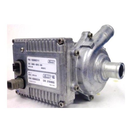
WP29 and WP32 Electric Water Pump
Installation Approval Documentation
This manual is effective for aftermarket and OEM installations
Part Number
1030085xxx
1030002xxx
Rev
Rev By
A
MPL/BF 4/9/13
C
BF
9970002273 Rev_C - 5/13/2014
Installation Manual
of the following part and serial numbers:
Date
Original Release
10/30/13
Formatting, Orientation, Checklist
and
Serial Number(s)
All
All
Description of Change
© 2013 EMP, Inc
Approved By
ECN2805
ECN3149
1
Advertisement
Table of Contents

Related Manuals for EMP WP29


Summary of Contents for EMP WP29
- Page 1 WP29 and WP32 Electric Water Pump Installation Manual Installation Approval Documentation This manual is effective for aftermarket and OEM installations of the following part and serial numbers: Part Number Serial Number(s) 1030085xxx 1030002xxx Rev By Date Description of Change Approved By...
-
Page 2: Product Overview
Service@emp-corp.com Product Overview The WP29 and WP32 are electrically powered fluid pumps available in 12 volt DC and 24 volt DC configurations. The pump is available with carbon steel, or stainless steel shafts for fluid compatibility. Proper installation of the pump will help ensure the performance and reliability of the electric pump while reducing the risk of damage to other components in the system. -
Page 3: Table Of Contents
Equipment Required for WP29 and WP32 Data Collection ............21 Inlet Pressure Measurement Test Procedure ................. 22 Test Data Log Sheet ........................24 Appendix B, WP29 and WP32 Installation Approval Registration and Check Sheet ......26 Installation Approval # ........................26 Product Installation Questionnaire ....................27... -
Page 4: Safety
If a tool, procedure, work method, or operating technique that not specifically recommended by EMP is used, you must satisfy yourself that it is safe for you and for others. You should ensure that the product will not be damaged or be made unsafe by the operation, maintenance, or repair procedures that you choose. -
Page 5: Purpose
EMP will participate in a design review if requested. Prior to production release of any system incorporating the WP29 and/or WP32, please take the time to fill out the included product installation registration form and e-mail to service@emp-corp.com. -
Page 6: Specifications
Specifications Specifications Dimensions Hole Locations/Bolt Spacing © 2013 EMP, Inc... -
Page 7: Material Listing Of Major External And Fluid Contacting Parts
1020 Carbon Steel Product Label M - 714 Connector Dupont Zytel Nylon 70G33L NOTE: SAE 440 Stainless Steel Shafts are offered as an option on EMP WP29 and WP32 Pumps. Contact customer service for part number information. © 2013 EMP, Inc... - Page 8 The pump hardware part and serial numbers are located on the upper label. The lower label identifies the Programmed Assembly number and the associated control software as the pump leaves the manufacturing facility. The EMP service tool can be used to confirm the pump software should calibration changes be required and new identification tags issued.
-
Page 9: Performance
3000 2500 2000 1500 1000 Flow (gpm) Static Pressure Rise -vs- Flow WP29 - 24 volt pump WP32 and WP29 -24V WP29 24V (1000) WP29 24V (2000) WP29 24V (3000) WP29 24V (4000) WP29 24V (4500) WP29 24V (max speed) Flow (gpm) ©... -
Page 10: Pump Limitations
Environment Environment cleanliness is crucial to pump life. The WP29 and WP32 are certified with an IP67 rating but debris collection in the weep pocket can lead to premature seal failure (See figure below). Shielding may be required to ensure debris does not enter the weep hole. If you have any questions regarding your installation contact EMP to ensure warranty coverage. -
Page 11: Inlet And Outlet Pressures
The configuration will be forced to have a 3000 rpm pump speed limit. “Inlet B” is also restrictive, and will require the WP29 and WP32 pump speeds to be limited to 3500 rpm, where “Inlet C” remains in the safe operating zone for all measured pump speeds and has no special limitations. -
Page 12: Fluid Level
Light Duty Partial Formulated Coolant: Reference ASTM D3306 for coolant quality and maintenance schedules. Based on field testing and experience, the WP29 and WP32 are compatible with the following coolant types: 1. Ethylene Glycol 2. HOAT ( Hybrid Organic Acid Technology) 3. -
Page 13: Plumbing
25mm (1.0 inch) in length. Deviations from the Recommended Plumbing must meet the Inlet Requirements and be approved by EMP Engineering. Please contact EMP customer service for installation review. Mounting Screws Mounting screws used should be M8 x 1.25 screws (qty=4). These must have a minimum thread engagement of 0.50 inch (12.7 mm) and be tightened to a torque of 15 ft-lb (20N-m). -
Page 14: Electrical Specifications And Requirements
(downward) impact on these numbers. This current is not generated every time the motor is started, but only when the ignition line is first applied. Vehicle Ignition Parameters Parameter Unit 13.5 or 27 IGN Current (13.5v) IGN Current (27.5v) Vin – Low (sleep) © 2013 EMP, Inc... -
Page 15: Schematics
Controller Connectors Mating Connectors The mating connectors and pins are available from EMP in kit #3170001077 for the 6 pin and #3170001078 for the 4 pin connector. IF CAN OR SERIAL TTL CONTROL IS NOT USED THE 6 PIN DTM CONNECTOR MUST BE BLOCKED OFF TO PREVENT ENTRY OF WATER OR DIRT WHICH WILL RESULT IN DAMAGE TO THE PUMP. -
Page 16: Wiring
Wiring or electrical harness should be captured by the grease supported at least every 18" to 20". To avoid possible fire or shock, do not pinch any wiring or electrical harnesses. © 2013 EMP, Inc... -
Page 17: Installation
1030085018, 1030085019, 1030085021, 1030085023 10° 0° 0° Nom -5°Nom ° -15° Horizontal Controller Orientation Part numbers for this orientation include: 1030002276, 1030002277, 1030002279, 1030002284, 1030002286, 1030002288, 1030085014, 1030085015, 1030085017, 1030085020, 1030085022, 1030085024 0° 10° 0° Nom -5°Nom -10° -15° © 2013 EMP, Inc... -
Page 18: Dual Orientation
Incorrect Pump Orientation and Reasons The WP29 and WP32 contain a mechanical seal; 0.1cc/hr may weep past the seal as a part of normal operation. To properly collect the weepage pump orientation is important. Too steep of an angle will not allow the fluid to collect in the weep pocket and evaporate off and the pump may appear to be leaking when in fact it is operating as designed. -
Page 19: Physical Inspection
NOTE: Mechanical Seal COOLANT MAY BE SEEN OUTSIDE THE EMP WP29 ELECTRIC WATER PUMP. design requires fluid between the shaft and the seal material. This fluid vaporizes and passes the seal, venting through the weep collection pocket. As the seal wears in, the amount of venting decreases but never to zero. -
Page 20: Troubleshooting
EMPower Connect™ Service Tool Monitoring operation and manual control of the pump can be accomplished using the service tool EMPower Connect which is part of the EMP Service Suite available at no cost on our website at: http://www.emp-corp.com/support/downloads/ To use EMPower Connect download and install on your PC. -
Page 21: Appendix A, Wp29 And Wp32 Installation Testing
The information provided in this document supplements the Installation Approval document and provides detailed information for service tool use with the WP29 and WP32. The information within this document may be helpful in developing unique system calibrations and mapping the operation of the cooling system. -
Page 22: Inlet Pressure Measurement Test Procedure
1. Install Instrumented WP29 and WP32 into the system. a. If a non-instrumented WP29 and WP32 is to be used with an external sensor, ensure the sensor is located within 2 inches of the pump inlet and 4 inches from the last bend in the supply plumbing. - Page 23 Appendix A, WP29 and WP32 Testing 5. To manually control the WP29 and WP32 pump speed: Step 1 Select “Manual Control” button Step 2 Select “Motor Enable” button Step 3 Enter pump test point speed Press the enter button Step 4 Record Test Data on the Installation Data Sheet Step 5 Adjust pump speed for the next data point and record test data.
-
Page 24: Test Data Log Sheet
Appendix A, WP29 and WP32 Testing Test Data Log Sheet Installation Description Pump Hardware & Software Numbers (Label) Fluid Type Unit or Vehicle Description and # Coolant Type Evaluation Date Evaluation Location Evaluator Contact Information NOTE: Controller Settings from EMPower Connect service tool... - Page 25 Appendix A, WP29 and WP32 Testing Installation Description Test Configuration Special Conditions: Test Data Log Pump Speed (rpm) 1000 2000 3000 3500 4000 4300 4600 Pump Current (Amps) Pump Voltage (VDC) Inlet Pressure (kPa/psi) Inlet/Outlet Temperature (F/C) Outlet Pressure (optional)
-
Page 26: Appendix B, Wp29 And Wp32 Installation Approval Registration And Check Sheet
Appendix B, EMPower Connect Service Tool Appendix B, WP29 and WP32 Installation Approval Registration and Check Sheet To be Completed by EMP Installation Approval # Submit Completed Forms to: Date Submitted 2701 North 30 Street Reviewer Escanaba, Michigan 49829 Approval Date Phone: 906-789-7497 www.emp-corp.com... -
Page 27: Product Installation Questionnaire
Is there a fluid level warning and/or switch to prevent Specifications - dry operation of the pump? List the type of system used Electrical Are the power and ground wires a minimum of 12 AWG Specifications - wire? Electrical © 2013 EMP, Inc... - Page 28 Plumbing Are the hoses/tubes supported to reduce the risk of Installation - rubbing? Plumbing Is the WP29 and WP32 inlet plumbing one inch internal Installation - Plumbing diameter from the coolant source? Are there 2-3 diameters of straight plumbing directly...
- Page 29 Are there any elevated areas in the inlet supply? Installation - NOTE: Areas where air can be trapped and prevent Plumbing coolant flow to the pump. The WP29 and WP32 is not a self-priming pump. Is the WP29 and WP32 more than 6 inches below the Installation -...
- Page 30 Engineered Machined Products Inc. 2701 North 30 Street Escanaba, Michigan 49829 Phone: 906-789-7497 www.emp-corp.com Service@emp-corp.com © 2013 EMP, Inc...
Need help?
Do you have a question about the WP29 and is the answer not in the manual?
Questions and answers