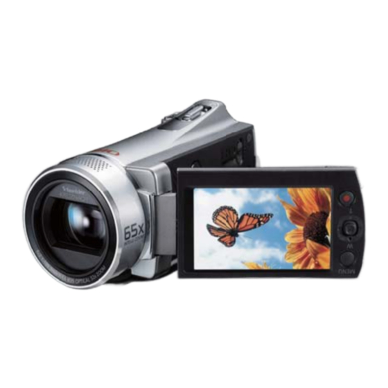
Samsung SMX-K40BN Service Manual

Samsung SMX-K40BN Service Manual

Chassis : k40
Hide thumbs Also See for SMX-K40BN:

Advertisement

SERVICE
DIGITAL MEMORY CAMCORDER
Chassis : K40
BASIC :
SMX-K40Bn
Application Models
nTSC : SMX-K40Bn, SMX-K44Bn, SMX-K45Bn,
SMX-K40Sn, SMX-K44Sn, SMX-K45Sn,
SMX-K40Ln, SMX-K44Ln, SMX-K45Ln
P A L : SMX-K40BP, SMX-K44BP, SMX-K45BP,
SMX-K40SP, SMX-K44SP, SMX-K45SP,
SMX-K40LP, SMX-K44LP, SMX-K45LP
Manual
1. Precautions
2. Product Specification
6. PCB Diagrams
COnTEnTS

Advertisement

Table of Contents
loading

Summary of Contents for Samsung SMX-K40BN

  • Page 1: Table Of Contents

    DIGITAL MEMORY CAMCORDER Chassis : K40 BASIC : SMX-K40Bn Application Models nTSC : SMX-K40Bn, SMX-K44Bn, SMX-K45Bn, SMX-K40Sn, SMX-K44Sn, SMX-K45Sn, SMX-K40Ln, SMX-K44Ln, SMX-K45Ln P A L : SMX-K40BP, SMX-K44BP, SMX-K45BP, SMX-K40SP, SMX-K44SP, SMX-K45SP, SMX-K40LP, SMX-K44LP, SMX-K45LP SERVICE Manual DIGITAL MEMORY CAMCORDER COnTEnTS 1.
  • Page 2 Mideast & Africa URL ; http://mea.samsungportal.com © Samsung Electronics Co., Ltd. JUL. 2009 This Service Manual is a property of Samsung Electronics Co .,Ltd. Printed in Korea Any unauthorized use of Manual can be punished under applicable International and/or domestic law.
  • Page 3: Disassembly And Reassembly

    4) Remove FPC Photo ASS'y Top FpC phoTo 1 SCREW (M 1.7 X 5B) RuBEER RighT 1 SCREW (M 1.7 X 5B) 1 SCREW (M 1.7 X 5B) Caution : FPC Must be remove with care Fig. 3-1 Ass'y Top Removal Samsung Electronics...
  • Page 4 3) Remove FPC Front 1 SCREW FpC FRonT (M 1.7 X 5B) ASS'y FRonT 1 SCREW (M 1.7 X 5B) 1 SCREW (M 1.7 X 5B) Caution : FPC Must be remove with care Fig. 3-2 Ass'y Front Removal Samsung Electronics...
  • Page 5 (M 1.7 X 5B) 1 SCREW (M 1.7 X 5B) FpC TERMinAl 1 SCREW (M 1.7 X 5B) 1 SCREW (M 1.7 X 5B) FpC REAR ASS'y RighT Caution : FPC Must be remove with care Fig. 3-3 Ass'y Right Removal Samsung Electronics...
  • Page 6 ASS'y lEFT 1 SCREW (M 1.7 X 5B) FpC lCD SSD MEMoRy pCB 1 SCREW (T 1.7 X 3B) 1 SCREW (T 1.7 X 3B) Caution : FPC Must be remove with care Fig. 3-4 Ass'y left Removal Samsung Electronics...
  • Page 7 Disassembly and Reassembly 3-1-5 Ass'y Camera Removal 1) Remove 1 Screw 2) Remove Main PCB 3) Remove Ass'y Camera MAin pCB 1 SCREW (M 1.7 X 5B) ASS'y CAMERA Fig. 3-5 Ass'y Carmera Removal Samsung Electronics...
  • Page 8 Disassembly and Reassembly Memo Samsung Electronics...
  • Page 9: Troubleshooting

    Refer to a pattern image of Table 4-1 Does a voltage-output to the L103, Check L103, L105, L106, L107, L108 L105, L106, L107, L108 work normally? Refer to a pattern image of Table 4-1, 4-2 Main board Repair/replacement Samsung Electronics...
  • Page 10 Of good SW206 SWITCH SOT-15SST (Fig. 4-1) 3 Pin or 4 Pin L103 Inductor 4.7uH (Fig. 4-2) 1 Pin 2 Pin L105 Inductor 4.7uH (Fig. 4-2) 1 Pin 2 Pin L106 Inductor 4.7uH (Fig. 4-2) 1 Pin 2 Pin Samsung Electronics...
  • Page 11 <Table 4-2 : Test Point Wave Pattern Image > Position of Names Standard Wave pattern image Replacement part Of good L107 Inductor 4.7uH (Fig. 4-2) 1 Pin 2 Pin L108 Inductor 4.7uH (Fig. 4-2) 1 Pin 2 Pin Samsung Electronics...
  • Page 12 3 7 0 8 - 0 0 2 6 2 0 3 7 0 8 - 0 0 2 6 2 0 CN203 CN301 Fig. 4-2 L103, L105, L106, L107, L108 C110 10000nF D102 C113 1SS416 10000nF Samsung Electronics D103 C114 10000nF 1SS416 R118 R112 R113 57.6K/F 34K/F 1M/F 12.0V...
  • Page 13 Check/Replace MIC, Audio Codec (IC701 NO. 26,27) Check/Replace Video Is Video_Out OK? AMP (IC704 NO1,6) (IC704 NO. 6) Test Completed. AUDIO : Sample of 1khz recording VIDEO : below is the sample AV_JACK_DET : JACK INSERTED AV_JACK_DET:JACK NOT INSERTED Samsung Electronics...
  • Page 14 Is 12V transited to Check D103 & IC101 D103 No1,2? Refer to a pattern image of Table 4-3 Is -7.5V transited Check Q103 & IC101 to Q103 No3? Refer to a pattern image of Table 4-3 Change CAMERA ASSY Samsung Electronics...
  • Page 15 <Table 4-3 : Test Point Wave Pattern Image > Position of Names Standard Wave pattern image Replacement part Of good C809 Ceramic 1000nF (Fig. 4-3) D103 Diode 1SS416 (Fig. 4-4) 1 Pin 2 Pin Q103 SCH2810 (Fig. 4-5) 3 Pin Samsung Electronics...
  • Page 16 R112 3 7 0 8 - 0 0 2 6 2 0 34K/F 1M/F 57.6K/F 12.0V CN301 D103 1PIN 9.85V R114 R119 R123 -7.5V 34K/F 470K/F 3.02V R108 R101 R102 220K 100K 57.6K Fig. 4-4 DP03 1,2 Pin Samsung Electronics...
  • Page 17 D 2 0 1 3.02V 1SS393 0404-001096 R108 R101 R102 R 1 2 5 C O N 3 0 1 220K 100K 57.6K 2 2 K 3 7 0 8 - 0 0 2 6 2 0 CN301 Samsung Electronics...
  • Page 18 (DIGITAL DATA,DCLK) Check serial port of 1.Check the connection FPC-LCD LCD control? 2.Check IC401 CN204 No 7~9 Refer to a pattern image of Fig 4-6 Input signal in CNL02 Check connection of LCD Panel pin normal? Change Assy-LCD 4-10 Samsung Electronics...
  • Page 19 R 5 1 2 GYRO_X_REF C 5 0 8 R 5 1 1 R 5 1 5 R 5 1 4 Samsung Electronics 4-11 GND4 1 0 0 n F 1 0 0 n F 1 0 0 K 1 0 0 K...
  • Page 20 Check X401 mally? X401= 12MHz Refer to a pattern image of Table 4-4 Does IC401(NIKE) Replace IC401 or Main B’d Work normally? Does it work normally Replace IC401 or Main B’d After having Image Upgrade? Repair is done 4-12 Samsung Electronics...
  • Page 21 Troubleshooting <Table 4-4 : Test Point Wave Pattern Image > Position of Wave pattern image Replacement part IC201 19pin (Fig. 4-7) USB Detect CN202(DP, DM) (Fig. 4-8) USB DP/DM X401 (Fig. 4-9) X401 12MHz Samsung Electronics 4-13...
  • Page 22 VCC_GYRO3V L 1 0 8 4 . 7 u H H_AD IC202 H_AD 4-14 Samsung Electronics MRMS501A C 1 1 3 D 1 0 2 R213 1 S S 4 1 6 1 0 0 0 0 n F LCD_OPEN...
  • Page 23 NOR_A[15] nADR15 NOR_A[14] nADR14 NOR_A[13] nADR13 NOR_A[12] nADR12 NOR_A[11] nADR11 NOR_A[10] nADR10 NOR_A[9] nADR09 NOR_A[8] nADR08 NOR_A[7] nADR07 NOR_A[6] nADR06 NOR_A[5] nADR05 NOR_A[4] nADR04 NOR_A[3] nADR03 NOR_A[2] Samsung Electronics 4-15 nADR02 NOR_A[1] nADR01...
  • Page 24 Troubleshooting M E M O 4-16 Samsung Electronics...
  • Page 25: Exploded View And Parts List

    5. Exploded View and Parts List 5-1 Ass'y Chassis -------------------------------------------------------------- 5-2 5-2 Ass'y Left --------------------------------------------------------------------- 5-4 5-3 Ass'y Right ------------------------------------------------------------------ 5-5 5-4 Ass'y LCD --------------------------------------------------------------------- 5-6 5-5 Ass'y Top ---------------------------------------------------------------------- 5-8 5-6 Ass'y Rear ----------------------------------------------------------------- 5-10 5-7 Ass'y Bottom ------------------------------------------------------------- 5-11 5-8 Ass'y Camera ------------------------------------------------------------ 5-12 5-9 Ass'y Front ----------------------------------------------------------------- 5-13 5-10 Electrical Parts List ------------------------------------------------ 5-14...
  • Page 26 ASSY RIGHT (T1.7 X 5B) (S.N.A) P391 : SMX-K44, SMX-K45 ONLY W127 (T1.7 X 3B) ASSY CAMERA (S.N.A) P001 W281 (T1.7 X 5B) ASSY LEFT (S.N.A) W281 (T1.7 X 5B) This Document can not be used without Samsung's authorization Samsung Electronics...
  • Page 27 Description ; Specification Q ty SNA Remark P001 AD92-00846A ASSY PCB MAIN;K40-PJ,SMX-K44BP/E P170 AD97-17559D ASSY FRONT;K40-PJ,K44,BLACK P391 AD92-00850A ASSY PCB-SSD;K40-PJ,MLC,SMX-K40N R001 AD73-00342A RUBBER-RIGHT;SMX-K40,URETHAN,70',RIGHT S W127 6003-001292 SCREW-TAPTYPE;CH(0.3),+,B,M1.7,L3,ZPC(BL W281 6001-001508 SCREW-MACHINE;CH(0.5),+,M1.7,L5,ZPC(BLK) Samsung Electronics This Document can not be used without Samsung's authorization...
  • Page 28 (T1.7 X 2.5B) Loc. No Parts No. Description ; Specification Q ty SNA Remark C322 AD61-04221A BRACKET-LEFT;SMX-K40,SUS,T0.7,W10,L30 L001 AD97-17554G ASSY LCD;K40-PJ,SMX-K44,BLACK P091 AD97-17553A ASSY CASE-LEFT;K40-PJ,K40,BLACK W313 6001-001510 SCREW-MACHINE;CH,+,M1.7,L2.5,NI PLT,SWRC This Document can not be used without Samsung's authorization Samsung Electronics...
  • Page 29 (S.N.A) Loc. No Parts No. Description ; Specification Q ty SNA Remark C069 AD61-04225A CASE-RIGHT;K40,PC,T1.5,W75,L50,BLK C014 AD97-17545A ASSY BELT-GRIP;Memory CAM,SMX-K40 C309 AD64-02670A BUTTON-RECORD;SMX-K40,ABS,BLK W371 6003-001453 SCREW-TAPTYPE;BH,+,B,M1.7,L4,ZPC(BLK) W281 6001-001508 SCREW-MACHINE;CH(0.5),+,M1.7,L5,ZPC(BLK) Samsung Electronics This Document can not be used without Samsung's authorization...
  • Page 30 L005 L014 W127 (T1.7 X 3B) ASSY PCB LCD MAGNET-LCD MIRROR (S.N.A) (S.N.A) C1082 FPC-LCD (S.N.A) L078 ASSY HINGE (S.N.A) L015 BRACKET-GROUND DISPLAY (S.N.A) MAGNET-LCD OPEN C1080 (S.N.A) L013 This Document can not be used without Samsung's authorization Samsung Electronics...
  • Page 31 KNOB-JOY LCD;DX210,PC,T2.0,W7.7,L7.4,BLA L005 AD97-18007D ASSY CASE-LCD TOP;K40,SMX-K44,BL L013 AD61-04226A CASE-LCD BOTTOM;SMX-K40,PC,T1.2,W45,L80, L014 AD63-04234A COVER-HINGE TOP;SMX-K40,ABS,T1.2,W12,L25 L015 AD63-04235A COVER-HINGE BOTTOM;SMX-K40,ABS,T1.2,W12, L078 AD97-18017A ASSY LCD-PANEL;K40-PJ,K40,PANEL_BACKLIGH W127 6003-001292 SCREW-TAPTYPE;CH(0.3),+,B,M1.7,L3,ZPC(BL W206 6001-001373 SCREW-MACHINE;PH,T0.5,+,M1.7,L3.0,ZPC(BL Samsung Electronics This Document can not be used without Samsung's authorization...
  • Page 32 Exploded Views and Parts List 5-5 Ass'y Top P099 C208 Z001 C679 F002 W371 (T1.7 X 4B) This Document can not be used without Samsung's authorization Samsung Electronics...
  • Page 33 Description ; Specification Q ty SNA Remark C208 AD61-12033A BRACKET-NUT;SV-D10,SECC,T0.8 C679 AD64-02665A BUTTON-PHOTO;SMX-K40,ABS, MP-0160R,NATUR F002 AD97-17519A ASSY FPC-PHOTO;K40-PJ,SMX-K40,PHOTO FPC P099 AD97-18008D ASSY CASE-TOP;K40,SMX-K44,BLK W371 6003-001453 SCREW-TAPTYPE;BH,+,B,M1.7,L4,ZPC(BLK) Z001 AD97-17600A ASSY ZOOM-VR;ABS,PET,IB-VC-Y0864/V,Membr Samsung Electronics This Document can not be used without Samsung's authorization...
  • Page 34 BRACKET-GROUND REAR;SMX-K40,STS,T0.15,W1 C1094 AD64-02674A INDICATOR-MODE LED;SMX-K40,PMMA,T2.5,MIL C208 AD61-12033A BRACKET-NUT;SV-D10,SECC,T0.8 C360 AD61-04232A BRACKET-REAR;SMX-K40,STS304,T0.5,W37,L45 FL348 3809-002364 FFC CABLE-FLAT;30V,80C,30mm,26P,0.5mm,AW P009 AD92-00847A ASSY PCB REAR;K40-PJ,SMX-K40N/XAA,NTSC,E P101 AD97-18009D ASSY CASE-REAR;K40,SMX-K44,BLK W206 6001-001373 SCREW-MACHINE;PH,T0.5,+,M1.7,L3.0,ZPC(BL 5-10 This Document can not be used without Samsung's authorization Samsung Electronics...
  • Page 35 Parts No. Description ; Specification Q ty SNA Remark C1093 AD63-04236A COVER-BATTERY;SMX-K40,PC,T1.5,W40,L73,BL C208 AD61-12033A BRACKET-NUT;SV-D10,SECC,T0.8 C834 AD61-04230A HOLDER-BATTERY;SMX-K40,ABS,T1,W13,L25,NT F001 AD97-17518A ASSY FPC-TERMINAL;K40-PJ,SMX-K40,TERMINA VS052 AD61-04227A CASE-BOTTOM;SMX-K40,PC,T1.5,W40,L93,BLK W371 6003-001453 SCREW-TAPTYPE;BH,+,B,M1.7,L4,ZPC(BLK) Samsung Electronics This Document can not be used without Samsung's authorization 5-11...
  • Page 36 ASSY CCD;K40-PJ,SMX-K40BP/EDC,PA C594 AD61-02368A PLATE-CCD;DRAGON2-PJ,AL,T1,W21,L25,X26 P052 AD67-00403A LENS FILTER-OLPF LERM1;LERM1,IR CUT/CRYS P053 AD60-00073A SPACER-CCD;CP-DX210,TPS,L11.5,BLK,T1.02, P259 AD97-17435A ASSY LENS-ZOOM;K40,HSKY-PJ,52X SD,- W127 6003-001292 SCREW-TAPTYPE;CH(0.3),+,B,M1.7,L3,ZPC(BL W206 6001-001373 SCREW-MACHINE;PH,T0.5,+,M1.7,L3.0,ZPC(BL W371 6003-001453 SCREW-TAPTYPE;BH,+,B,M1.7,L4,ZPC(BLK) 5-12 This Document can not be used without Samsung's authorization Samsung Electronics...
  • Page 37 W300 (T1.4 X 5B) Loc. No Parts No. Description ; Specification Q ty SNA Remark VS006 AD97-17635A ASSY SPEAKER;ASSY SPEAKER,K40-PJ,ISSR-17 VS050 AD97-17634A ASSY MIC;K40,SMX-K40,STEREO MIC,35mm W300 6003-001503 SCREW-TAPTYPE;PH,+,B,M1.4,L5,ZPC(BLK),SW Samsung Electronics This Document can not be used without Samsung's authorization 5-13...
  • Page 38 C-CER,CHIP;1000nF,10%,25V,X5R,TP C436 2203-006048 C-CER,CHIP;100nF,10%,10V,X7R,TP, C213 2203-006048 C-CER,CHIP;100nF,10%,10V,X7R,TP, C437 2203-006048 C-CER,CHIP;100nF,10%,10V,X7R,TP, C214 2203-000425 C-CER,CHIP;.018nF,5%,50V,C0G,TP, C438 2203-006048 C-CER,CHIP;100nF,10%,10V,X7R,TP, C439 2203-006048 C-CER,CHIP;100nF,10%,10V,X7R,TP, C215 2203-000425 C-CER,CHIP;.018nF,5%,50V,C0G,TP, C216 2203-005055 C-CER,CHIP;0.0056nF,0.25pF,50V,N C440 2203-006048 C-CER,CHIP;100nF,10%,10V,X7R,TP, 5-14 This Document can not be used without Samsung's authorization Samsung Electronics...
  • Page 39 C-CER,CHIP;100nF,10%,10V,X7R,TP, C907 2203-006048 C-CER,CHIP;100nF,10%,10V,X7R,TP, C908 2203-005065 C-CER,CHIP;1000nF,+80-20%,10V,Y5 C628 2203-006048 C-CER,CHIP;100nF,10%,10V,X7R,TP, C909 2203-006048 C-CER,CHIP;100nF,10%,10V,X7R,TP, C629 2203-006048 C-CER,CHIP;100nF,10%,10V,X7R,TP, C910 2203-006048 C-CER,CHIP;100nF,10%,10V,X7R,TP, C630 2203-006048 C-CER,CHIP;100nF,10%,10V,X7R,TP, C631 2203-006048 C-CER,CHIP;100nF,10%,10V,X7R,TP, C911 2203-006048 C-CER,CHIP;100nF,10%,10V,X7R,TP, Samsung Electronics This Document can not be used without Samsung's authorization 5-15...
  • Page 40 C-CER,CHIP;100nF,10%,16V,X7R,100 L703 2703-002723 INDUCTOR-SMD;22UH,10%,2012 L801 2703-002723 INDUCTOR-SMD;22UH,10%,2012 CB14 2203-006158 C-CER,CHIP;100nF,10%,16V,X7R,100 L802 2703-002723 INDUCTOR-SMD;22UH,10%,2012 CB16 2203-000489 C-CER,CHIP;2.2nF,10%,50V,X7R,TP, L901 2703-002723 INDUCTOR-SMD;22UH,10%,2012 CB17 2203-006361 C-CER,CHIP;10000nF,10%,10V,X5R,T CB18 2203-000233 C-CER,CHIP;0.1nF,5%,50V,C0G,TP,1 L902 2703-002723 INDUCTOR-SMD;22UH,10%,2012 5-16 This Document can not be used without Samsung's authorization Samsung Electronics...
  • Page 41 R-CHIP;15Kohm,1%,1/10W,TP,1608 R405 2007-000172 R-CHIP;10ohm,5%,1/16W,TP,1005 R406 2007-000172 R-CHIP;10ohm,5%,1/16W,TP,1005 R203 2007-000583 R-CHIP;22Kohm,1%,1/10W,TP,1608 R407 2007-000172 R-CHIP;10ohm,5%,1/16W,TP,1005 R204 2007-008213 R-CHIP;4.3Kohm,1%,1/16W,TP,1005 R409 2007-000173 R-CHIP;22ohm,5%,1/16W,TP,1005 R205 2007-000772 R-CHIP;33Kohm,1%,1/10W,TP,1608 R206 2007-008417 R-CHIP;34Kohm,1%,1/16W,TP,1005 R410 2007-000172 R-CHIP;10ohm,5%,1/16W,TP,1005 Samsung Electronics This Document can not be used without Samsung's authorization 5-17...
  • Page 42 R-CHIP;100Kohm,5%,1/16W,TP,1005 R922 2007-000142 R-CHIP;2.7Kohm,5%,1/16W,TP,1005 R923 2007-000636 R-CHIP;270Kohm,5%,1/16W,TP,1005 R516 2007-007142 R-CHIP;10Kohm,1%,1/16W,TP,1005 R924 2007-000162 R-CHIP;100Kohm,5%,1/16W,TP,1005 R517 2007-007142 R-CHIP;10Kohm,1%,1/16W,TP,1005 R925 2007-001307 R-CHIP;180ohm,5%,1/16W,TP,1005 R518 2007-000171 R-CHIP;0ohm,5%,1/16W,TP,1005 R519 2007-000171 R-CHIP;0ohm,5%,1/16W,TP,1005 R926 2007-001307 R-CHIP;180ohm,5%,1/16W,TP,1005 5-18 This Document can not be used without Samsung's authorization Samsung Electronics...
  • Page 43 R-CHIP;22Kohm,5%,1/16W,TP,1005 CL04 2203-006348 C-CER,CHIP;1000nF,10%,25V,X5R,T RA68 2007-001325 R-CHIP;3.3Kohm,5%,1/16W,TP,1005 CL05 2203-006348 C-CER,CHIP;1000nF,10%,25V,X5R,T RA69 2007-000070 R-CHIP;0ohm,5%,1/10W,TP,1608 CL06 2203-006348 C-CER,CHIP;1000nF,10%,25V,X5R,T RA70 2007-000070 R-CHIP;0ohm,5%,1/10W,TP,1608 CL07 2203-006320 C-CER,CHIP;2200nF,10%,16V,X7R,T RA71 2007-000171 R-CHIP;0ohm,5%,1/16W,TP,1005 CL08 2203-006320 C-CER,CHIP;2200nF,10%,16V,X7R,T Samsung Electronics This Document can not be used without Samsung's authorization 5-19...
  • Page 44 TR-DIGITAL;DTC143EE,NPN,150mW,4 W206 6001-001373 SCREW-MACHINE;PH,T0.5,+,M1.7,L3 RR01 2007-001306 R-CHIP;150ohm,5%,1/16W,TP,1005 W206 6001-001373 SCREW-MACHINE;PH,T0.5,+,M1.7,L3 RR02 2007-001306 R-CHIP;150ohm,5%,1/16W,TP,1005 W281 6001-001508 SCREW-MACHINE;CH(0.5),+,M1.7,L5 RR03 2007-001307 R-CHIP;180ohm,5%,1/16W,TP,1005 W281 6001-001508 SCREW-MACHINE;CH(0.5),+,M1.7,L5 RR04 2007-000138 R-CHIP;100ohm,5%,1/16W,TP,1005 W298 6003-001508 SCREW-TAPTYPE;PH,+,B,M1.4,L3,NI 5-20 This Document can not be used without Samsung's authorization Samsung Electronics...
  • Page 45 SCREW-TAPTYPE;PH,+,B,M1.4,L5,ZP W300 6003-001503 SCREW-TAPTYPE;PH,+,B,M1.4,L5,ZP W313 6001-001510 SCREW-MACHINE;CH,+,M1.7,L2.5,NI W371 6003-001453 SCREW-TAPTYPE;BH,+,B,M1.7,L4,ZP W371 6003-001453 SCREW-TAPTYPE;BH,+,B,M1.7,L4,ZP W371 6003-001453 SCREW-TAPTYPE;BH,+,B,M1.7,L4,ZP W371 6003-001453 SCREW-TAPTYPE;BH,+,B,M1.7,L4,ZP W398 6003-001300 SCREW-TAPTYPE;CH,+,B,M1.7,L4,ZP W421 6003-001434 SCREW-TAPTYPE;CH,+,B,M1.7,L9,ZP W422 6003-001746 SCREW-TAPTYPE;PH,+,B,M1.7,L8,PA Samsung Electronics This Document can not be used without Samsung's authorization 5-21...
  • Page 46 Exploded Views and Parts List Memo 5-22 This Document can not be used without Samsung's authorization Samsung Electronics...
  • Page 47: Schematic Diagrams

    7-14 GYRO (Main PCB) -------------------------------------------------------------------------------------- 7-15 7-15 CCD (CCD PCB) ------------------------------------------------------------------------------------------ 7-16 7-16 LCD (LCD PCB) ------------------------------------------------------------------------------------------- 7-17 7-17 Rear (Rear PCB) ---------------------------------------------------------------------------------------- 7-18 7-18 SSD Memory (SSD Memory PCB) ------------------------------------------------------------- 7-19 Samsung Electronics This Document can not be used without Samsung's authorization...
  • Page 48: All Block Diagram

    Schematic Diagrams 7-1 All block Diagram This Document can not be used without Samsung's authorization Samsung Electronics...
  • Page 49: System Flow And Operation

    ATA IF VCC_CCD12V VCC_CCD-7.5V VCC_CAM3V VCC_CAM5V VCC_M5V VCC_2.5V VCC_1.2V VCC_A3V CAM_DD_ON VCC_3V VCR_DD_ON LCD_ON VCC_1.8V LCD_BL_ON VCC_5V H.264 HDUP_27M UPSCALER POWER, MODE, EASY-Q, HD-UP,LCD_ ENHANCER,DISPLAY,5WAY,REC,MENU MICOM R5F64112 Fig. 7-1 Samsung Electronics This Document can not be used without Samsung's authorization...
  • Page 50: Dc/Dc (Main Pcb)

    10000nF R113 R118 R112 34K/F 1M/F PI_GND2 PI_GND4 PI_GND8 57.6K/F PI_GND6 12.0V PI_GND1 PI_GND3 PI_GND5PI_GND7 9.85V R114 R119 R123 -7.5V 34K/F 470K/F 3.02V R108 R101 R102 220K 100K 57.6K This Document can not be used without Samsung's authorization Samsung Electronics...
  • Page 51: Dc/Dc Waveform (Main Pcb)

    470K/F 3.02V R101 R102 R108 100K 57.6K 220K These are the waveforms of SMX-K40 Caution) There can be some differences (Voltage, Frequency, stc.) among cameras. L108 1PIN L108 2PIN Samsung Electronics This Document can not be used without Samsung's authorization...
  • Page 52: Charger (Main Pcb)

    SW206 3,4 PIN GYRO_X GND4 GYRO_X_REF GND4 C213 GYRO_Y GND4 100nF GYRO_Y_REF These are the waveforms of SMX-K40 Caution) There can be some differences (Voltage, Frequency, stc.) among cameras. This Document can not be used without Samsung's authorization Samsung Electronics...
  • Page 53: Micom (Main Pcb)

    JTCK CHK_REAR R360 10K 3 CE X301 SYS_3V 12MHZ JTRST R362 DEBUG_E8_BUSY nTRST DEBUG_EB_BUSY JRTCK C316 RTCK C308 C317 0.012nF 100nF DSP_RESET 0.012nF DEBUG_RX nSRST DEBUG_RX RESET R356 RESET Samsung Electronics This Document can not be used without Samsung's authorization...
  • Page 54: Dsp (Main Pcb)

    DSP_D2.5V ATA_D[12] DSP_D2.5V ATA_D[11] DSP_D3V DSP_D3V NOR_A[0-15] ATA_D[10] ATA_D[9] ATA_D[8] ATA_A[0] ATA_A[1] ATA_A[2] ATA_RST ATA_INTRQ ATA_IORD ATA_CS0 ATA_D[7] ATA_D[6] ATA_D[5] ATA_D[4] ATA_D[3] TPS03 R416 R417 R418 100K 100K 100K This Document can not be used without Samsung's authorization Samsung Electronics...
  • Page 55: Onenand / Ddr (Main Pcb)

    DDR_UDQS VSS2 R519 R509 R513 DDR_LDM NOR_nWE LDM_1 DDR_LDM DDR_CLK DDR_UDM DDR_CLK UDM_2 DDR_UDM R501 DDR_nCLK JTRST DDR_nCLK R507 DDR_CKE DDR_CKE NOR_nOE NOR_RDY R510 VCC_CORE NOR_CS0 VCC_IO C503 100nF Samsung Electronics This Document can not be used without Samsung's authorization...
  • Page 56: Upscaler (Main Pcb)

    Pin4 TMDS_CLK+ TMDS_CLK- Pin6 TMDS_CLK+ AUD_SDI0 TMDS_CLK- DDC/CEC_GND Pin9 D603 B605 180ohm VCC_1.2V HDMI_CEC Pin1 C647 HDMI_SCL B606 10nF HDMI_5V Pin4 180ohm HOT_PLUG_DET HDMI_SDA Pin6 HOT_PLUG_DET Pin9 HDMI_5V 7-10 This Document can not be used without Samsung's authorization Samsung Electronics...
  • Page 57: Audio (Main Pcb)

    Y/C_OUT J701 T38-905-61G VAMP_nPS V.AMP VAMP_nPS C743 A-R_OUT POS.1 100nF 2GND POS.2 TO SYSCON VAMP_nPS VIDEO_OUT POS.3 3SHDN AV_JACK_DET AV_JACK_DET AV_JACK_DET POS.4 A-L_OUT TO UPSCALER POS.5 UP_A_MCLK UP_A_MCLK Samsung Electronics This Document can not be used without Samsung's authorization 7-11...
  • Page 58: Afe (Main Pcb)

    AD[9] AD[9] AD[3] C807 BYPP AD[10] AD[10] 100nF C804 R801 AD[11] 0.033nF AD[11] AD[2] C808 CDS_SCLK 470nF CDS_SCLK CDS_SO CDS_SO CDS_CS CDS_CS C810 100nF C811 C812 100nF 100nF 7-12 This Document can not be used without Samsung's authorization Samsung Electronics...
  • Page 59: Motor (Main Pcb)

    Y_HI- Y_HO- Y_HI- Y_HO+ R901 Y_HO+ 4.7K Y_HI+ Y_HI+ Y_HI+ Y_HI+ Y_HO+ Y_HO+ R926 C908 *FROM 1000nF DC/DC Q902 C910 DTC143EE VCC_1.8V 100nF VCC_1.8V R902 CN901 R903 100K Samsung Electronics This Document can not be used without Samsung's authorization 7-13...
  • Page 60: Ois Driver (Main Pcb)

    Y_HO- B_OUTPUT C_OUTPUT Y_HO- P_ACT_DR+ RA90 P_DR+ Y_GAIN_ADJ Y_GAIN_ADJ P_ACT_DR+ P_ACT_DR- RA91 P_DR- RA59 P_ACT_DR- RA57 Y_ACT_DR+ RA92 Y_DR+ Y_ACT_DR+ 5.1K Y_LOW_BOOST1 Y_ACT_DR- RA93 Y_DR- Y_ACT_DR- VREF RA58 7-14 This Document can not be used without Samsung's authorization Samsung Electronics...
  • Page 61: Gyro (Main Pcb)

    START_CATH START_CATH RB03 QB05 START_EMMI KTA1532T VCC_M5V RB16 RB18 RB19 RB04 LIMIT_CATH COVER_CTL2 CB12 LIMIT_CATH QB06 100nF FROM TO CPH3209 LENS COVER QB01 RB10 RN1104 0504-000168 Sheet 11 Samsung Electronics This Document can not be used without Samsung's authorization 7-15...
  • Page 62: Ccd (Ccd Pcb)

    CC06 100nF 100nF CC05 100nF VSUB VSUB VSUB CC04 VSUB RC03 2.2nF 100K CC03 KDS160 100nF DC01 VOUT RC01 CC02 100nF VOUT CCD_OUT 2SK1070 QC01 VOUT RC02 3.3K 7-16 This Document can not be used without Samsung's authorization Samsung Electronics...
  • Page 63: Lcd (Lcd Pcb)

    LCD_3V VSYSC LCD3V BL_10V LCD_DCLK BL_10V BL10V_FB DCLK BL10V_FB LCD_MIRROR LCD_D7 LCD_MIROR DATA7 LCD_D6 DATA6 LCD_D5 DATA5 LCD_D4 DATA4 LCD_D3 DATA3 LCD_D2 DATA2 LCD_D1 DATA1 LCD_D0 DATA0 VCOM Samsung Electronics This Document can not be used without Samsung's authorization 7-17...
  • Page 64: Rear (Rear Pcb)

    DR03 SD_D[1] VCC_3V DAT1 VCC_3V SD_nINS VCC_3V VCC_3V CR04 SD_WP 100nF CHG_LED1 CHG_LED1(ORG) CHG_LED2 CD/WP CHG_LED2(GRN) CAM_LED_CTL CAM_LED_CTL PLAY_LED_CTL PLAY_LED_CTL SYS_3V SYS_3V KEY_MODE KEY_MODE KEY_PHOTO KEY_PHOTO KEY_REC KEY_REC 7-18 This Document can not be used without Samsung's authorization Samsung Electronics...
  • Page 65: Ssd Memory (Ssd Memory Pcb)

    F1CLE 16CLE N.C_14 F1D[3] F1ALE 17ALE I/O3 F1WE F1D[2] 18WE I/O2 CM34 F1D[1] 19WP I/O1 0.056nF F1D[0] 20N.C_5 I/O0 IOCS16 21N.C_6 N.C_13 22N.C_7 N.C_12 23N.C_8 N.C_11 24N.C_9 N.C_10 Samsung Electronics This Document can not be used without Samsung's authorization 7-19...
  • Page 66 Schematic Diagrams Memo 7-20 This Document can not be used without Samsung's authorization Samsung Electronics...
  • Page 67: Alignment And Adjustment

    (09:43:32 Mar 30 2009) : [MENU] EXIT (2009-05-28) : LAST EEPROM TABLE Fig. 8-1 > HALL + IRIS + WB3100 + WB5100 + LENS + 3M LENS + ZOOM VR (09:43:32 Mar 30 2009) : [MENU] EXIT (2009-05-28) : LAST EEPROM TABLE Fig. 8-2 Samsung Electronics...
  • Page 68 (09:43:32 Mar 30 2009) : [MENU] EXIT (2009-05-28) : LAST EEPROM TABLE (2009-05-28) : LAST EEPROM TABLE Push the OK Button If the set needs to adjust the lens, choose the 'ALL INIT'. Fig. 8-6 If not, choose the 'CAM INIT' Fig. 8-5 Samsung Electronics...
  • Page 69 Connect the AV cable to Input port of Monitor or TV. After entering the Admin mode, press the OK button in "CAMERA ADJUST" menu. Press the OK button in "IRIS" menu. Press the OK button in "YES" . Adjustment completed!"displays after finishing IRIS Adjust. Samsung Electronics...
  • Page 70 Press the OK button after entering "CAMERA ADJUST". - Press the OK button in "Zoom VR" menu. - Press the OK button in "YES" menu. Then Micom finds out Zoom VR Center position. Store Zoom VR Center Value Adjustment completed!"displays after finishing VR check. Samsung Electronics...
  • Page 71 The camera should be in "E-E" mode (Video Record) Press the OK button after entering "CAMERA ADJUST" - Press the OK button in "OIS" - Press the OK button in "YES" The actuator moves left/right and then moves up/down "Adjustment OK" displays after finishing OIS adjust. Samsung Electronics...
  • Page 72 7) When the DSP F/W is complete, you will be prompted with a message automatically - select "YES" when asked "Update MICOM F/W?" 8) "After update is started, the LCD monitor will resemble Fig 8-10 below Fig. 8-10 Samsung Electronics...
  • Page 73 Alignment and Adjustment 9) When complete, turn the unit on and check F/W. [menu] -> Left Key -> [setting] -> Up Key -> Version Fig. 8-11 Caution : DO NOT power of the set OR eject the card until the update is complete. When the update is complete the unit will turn off automatically The unit should be plugged into the AC adaptor and DO NOT attempt F/W with just the battery. Samsung Electronics...
  • Page 74 Alignment and Adjustment Memo Samsung Electronics...

Table of Contents