Table of Contents
Advertisement
Quick Links
Advertisement
Table of Contents

Subscribe to Our Youtube Channel
Related Manuals for SMAR CD600 Plus


Summary of Contents for SMAR CD600 Plus
- Page 2 Specifications and information are subject to change without notice. Up-to-date address information is available on our website. web: www.smar.com/contactus.asp...
- Page 3 Introduction INTRODUCTION The CD600 Plus Universal Multi-Loop Controller is the next generation of a successful and very reliable Smar Multi-Loop Controller, the CD600. Now using modern electronics and new technologies, it is smaller, lighter and even more powerful than its predecessor.
- Page 4 CD600 Plus - User’s Manual...
-
Page 5: Table Of Contents
OPERATION................................3.1 TYPICAL DESCRIPTION OF A BLOCK..........................3.1 THE LOOPS ...................................3.2 TAGS ..................................3.2 HOW TO PROGRAM THE CD600 PLUS........................3.2 EXAMPLE OF A CONFIGURATION ......................... 3.2 SECTION 4 - FUNCTION BLOCKS LIBRARY....................4.1 FUNCTION TABLE ..............................4.2 FUNCTION 01 - ANALOG INPUT (AI) ........................4.3 OPERATION ..................................4.3... - Page 6 CD600 Plus - User’s Manual FUNCTION 20 - BATCH COMPARATOR (BAT)..................... 4.55 OPERATION ..................................4.55 FUNCTION 21 - SETPOINT GENERATOR (SPG) ....................4.56 OPERATION ..................................4.56 FUNCTION 22 - DOUBLE ALARM (ALM) ....................... 4.58 OPERATION ..................................4.58 FUNCTION 23 - LIMITER WITH ALARM (LIMT)..................... 4.60 OPERATION ..................................4.60...
- Page 7 LOCAL CONDITIONS FOR INSTALLATION .........................9.1 ENVIRONMENT CONDITIONS..............................9.1 PRECAUTIONS AGAINST ELECTROMAGNETIC NOISE ....................9.1 EQUIPMENT INSTALLATION..............................9.2 WIRING ....................................9.3 CD600 VERSUS CD600 PLUS ..........................9.7 CONF600 PLUS INTRODUCTION ..............................10.1 MAIN FEATURES..............................10.1 SECTION 10 - SYSTEM INSTALLATION ....................10.3 SYSTEM REQUIREMENTS ............................ 10.3 INSTALLATION ...............................
- Page 8 ELECTRICAL INSTALLATION OF THE CONTROLLER ...................... A.3 CONTROL STRATEGY CONFIGURATION.......................... A.5 ESTABLISHING THE COMMUNICATION BETWEEN THE CONTROLLER AND THE COMPUTER........A.5 APPENDIX B............................... B.1 RETURNING MATERIALS ............................B.1 FSR – SERVICE REQUEST FORM..........................B.3 APPENDIX C - SMAR WARRANTY CERTIFICATE .................. C.1...
-
Page 9: Section 1 - Operation
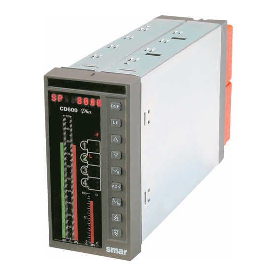
Section 1 OPERATION CD600 Plus Front Panel The CD600 Plus front panel has 3 bargraphs, an alphanumeric display, a group of keys for adjustment and control and LEDs for signaling. Fig 1.1 - Front Panel Bargraph Description Indication of monitored loop's Setpoint it is indicated on the green 101 LEDs bargraph. -
Page 10: Loop Selection
CD600 Plus - User’s Manual Keys Description Selects the variable to be shown in the alphanumeric display. Selects the loop to be monitored on the front panel. Increases the value of the variable shown on the display. Decreases the value of the variable shown on the display. -
Page 11: Changing The Alphanumeric Display Bright
Operation CONFIGURABLE BLOCK TYPE DEFAULT MNEMONIC MNEMONIC BURNOUT AI1 OUT BURNOUT AI2 OUT BURNOUT AI3 OUT BURNOUT AI4 OUT BURNOUT AI5 OUT BURNOUT AI6 OUT BURNOUT AI7 OUT BURNOUT AI8 OUT DEV/BURNOUT AO1 OUT DEV/BURNOUT AO2 OUT DEV/BURNOUT AO3 OUT DEV/BURNOUT AO4 OUT DEVIATION... - Page 12 CD600 Plus - User’s Manual...
-
Page 13: Section 2 - Tuning
Section 2 TUNING Proportional gain, Integral time and Derivative time constants of any Proportional, Integral, Derivative (PID) block existing in the controller's configuration may be adjusted from the front panel without using the Programmer. To make it possible, it is necessary to set the CACT parameter, of the respective PID block, to "0"... - Page 14 CD600 Plus - User’s Manual...
-
Page 15: Section 3 - Programming
Section 3 PROGRAMMING Operation The programming of the SMAR CD600 Digital Controller is based on the concept of freely interconnectable Function Blocks. The interconnection is done in accordance to the control strategy defined by the user. All the function blocks already exist in a part of the memory not accessible by the user. -
Page 16: The Loops
Loop. If no blocks are configured for the General Loop, at least a Tag must be given. How to Program the CD600 Plus When the CD600 Plus leaves the factory, with a default configuration named "4 LOOPS" (see Section 5). This configuration can be changed to fit a particular application, or can be replaced by a new one. - Page 17 CD600 Plus. A) Adjusting the identification address of the CD600 Plus: • Press the <ACK> key in the front panel of the CD600 Plus and keep it pressed for a few seconds until the display changes its message. •...
- Page 18 CD600 Plus - User’s Manual • Start a project file clicking in New, , on the toolbar. • Right click on Loop G on the palette and type “FIC100” as project name. • With another right click on Loop 1, “Flow” can be the name of the other loop.
- Page 19 Programming E) Editing the parameters: • Click on the Select tool, , and right click on the block for the popup menu to appear. Select the option Edit Parameters to open the dialog box of each block and adjust the parameter values as indicated in the following table: Function Block Parameters...
- Page 20 CD600 Plus - User’s Manual G) Downloading the configuration: • Once the controller is selected, click on Download to download the block configuration for the controller. H) Monitoring the blocks: The block outputs can be monitored while the controller is operating, thus not disturbing the process.
-
Page 21: Section 4 - Function Blocks Library
Section 4 FUNCTION BLOCKS LIBRARY... -
Page 22: Function Table
CD600 Plus - User's Manual Function Table FUNCTION MNEM BLOCK NUMBER DESCRIPTION PAGE Nº 001/002/003/004/005/006/007/008 ANALOG INPUT 009/010/011/012 CURRENT OUTPUT 013/014/015/016 VOLTAGE OUTPUT 017/018 DIGITAL INPUT 019/020/021/022/023/024/025/026 DIGITAL OUTPUT 027/028/029/030 FRONT VIEW 031/032/033/034 LOCAL/REMOTE SP SELECTOR 4.10 035/036/037/038 AUTOMATIC/MANUAL STATION 4.13... -
Page 23: Function 01 - Analog Input (Ai)
Library of Function Blocks Function 01 - Analog Input (AI) Operation All the analog inputs have a corresponding Analog Input block. The analog input 2, for example, which is connected to terminal 2, corresponds to block BLK002. The input to the circuit is always a voltage signal (0-5 V or 1-5 V). -
Page 24: Function 02 - Current Output (Co)
CD600 Plus - User's Manual Function 02 - Current Output (CO) Operation The block input, in percentage, is calibrated and converted into an analog current signal. A feedback of this current is sent to a comparator, which also receives the input signal. If there is a deviation greater than the ADEV (allowable deviation) parameter, the discrete output Deviation will be activated. -
Page 25: Function 03 - Voltage Output (Vo)
Library of Function Blocks Function 03 - Voltage Output (VO) BLK 013/014/015/016 VOLTAGE 6 /7/8/9 CALIBRATION DRIVER 100 % Operation The block input in percentage is calibrated and converted into an analog voltage signal sent to the terminal block. This block includes a parameter, which allows signal type selection, i.e., it makes 0-100% correspond to 1-5 Vdc/0-5 Vdc (direct type) or to 5-1 Vdc/ 5-0 vdc (reverse type). -
Page 26: Function 04 - Digital Input (Di)
CD600 Plus - User's Manual Function 04 - Digital Input (DI) BLK 017/018 3-24V OR OPEN CONTACT (HIGH LEVEL) 21/22 0-1,7V OR CLOSED CONTACT (LOW LEVEL) Operation If the input block terminal is open (impedance > 50 KΩ) in relation to the Digital Ground terminal or with a voltage between 3 and 24 Vdc, the signal will be considered as high logic level and the value 100% (high logic level) will be available in the block output. -
Page 27: Function 05 - Digital Output (Do)
Library of Function Blocks Function 05 - Digital Output (DO) Operation This block can perform a logic operation with inputs A and B. The output is sent to a two-position selector switch. The other position is connected to input C. A high logic level at D, switches CH1 to position "1", making the output equal to safety input C. -
Page 28: Function 06 - Front View (Fv)
CD600 Plus - User's Manual Function 06 - Front View (FV) Operation This block leads inputs A, B, C to bargraphs SP, PV and MV respectively, and in the default condition, associates these inputs to the mnemonics SP, PV and MV on the display. - Page 29 Library of Function Blocks TYPE MNEM DESCRIPTION RANGE DEFAULT AMSP Three-character mnemonic for SP ASPZ 0% for SP in engineering units -10000 to 10000 ASPM 100% for SP in engineering units -10000 to 10000 100.00 AMPV Three-character mnemonic for PV APVZ 0% for PV in engineering units -10000 to 10000...
-
Page 30: Function 07 - Local/Remote Sp Selector (L/R)
CD600 Plus - User's Manual Function 07 - Local/Remote SP Selector (L/R) BLK 031/032/033/034 RATE OF CHANGE 225/226 LIMITER 227/228 REMOTE 31/33 35/37 REGISTER LOCAL 32/34 36/38 Operation This block allows Setpoint selection by pressing the key <L/R> (Local/Remote), Setpoint adjustment by pressing keys <Δ>... - Page 31 Library of Function Blocks The controller can also be locked in Local or in Remote by the parameter CLKR. After a power interruption, the controller will return to operation in the mode (Local or Remote) selected by the parameter CTON. The block features bumpless Local-Remote transfer, with adjustable changing rate (Slew Rate, ASLW).
- Page 32 CD600 Plus - User's Manual In the above configuration, when in Local mode, actuation is performed in the register of Block 031 and, in Remote mode, in Block 099, although the visualized output is that of Block 031. TYPE MNEM...
-
Page 33: Function 08 - Automatic/Manual Station (A/M)
Library of Function Blocks Function 08 - Automatic/Manual Station (A/M) Operation This block allows the operator to actuate the controller output directly, whenever necessary. In the most common application, the output signal of one of the PID blocks is linked to the input A of the A/M block, its output being linked to a current output block. - Page 34 CD600 Plus - User's Manual If CH1 is in position "0" (equivalent to Automatic), the letter M will blink faster than when in Forced Manual and the signal at the output will be the same signal of input B. The position of switch CH1 after input C returning to a low logic level is determined by parameter CSA1, with the following options: last position, position "1"...
- Page 35 Library of Function Blocks CHST - RESTART CONDITION CHST configure the operating mode of the respective loop after a power interruption. CLIM-OUTPUT LIMITER ONLY ON AUTOMATIC The output limiter actuates normally in both operating modes: manual and automatic. CLIM allows the limiter to actuate only on the automatic mode.
- Page 36 CD600 Plus - User's Manual TYPE MNEM DESCRIPTION RANGE DEFAULT 0 - No Lock 1 - When Input D has a high logic level CLMV Locks < > and < > keys 2 - When Input C has a high logic level...
-
Page 37: Function 09 - Advanced Pid (Pid)
Calculation of the PID prevents the saturation of the output by the integral mode (anti- reset-windup). Saturation limits are adjustable by the user, a unique feature of the SMAR CD600 Digital Controller, that brings more flexibility to the control strategy. - Page 38 CD600 Plus - User's Manual Fig 4.9.1 - PI Sampling ACTION (CACT) There are processes that require the output signal to increase when the Process Variable increases, hile others require the other way around. Parameter CACT selects the type of action: TYPE 0, 2, 4 or 6 - Output signal decreases when PV increases −...
- Page 39 Library of Function Blocks Control Algorithm The CD600 offers two control algorithms: Parallel or Ideal algorithm de(t ∫ MV(t Noninteractive or ISA algorithm de(t ∫ MV(t [e(t Parameters 0, 1, 2 or 3 select the parallel or ideal. Parameters 4, 5, 6 or 7 select the noninteractive or ISA. For the noninteractive option, when K =0 the controller is automatically set as ID.
- Page 40 CD600 Plus - User's Manual GAP CONTROL (CBND AND CSGA) There are applications where the control is unstable near the Setpoint due to actuator dead band, noise or other reasons. In this case, it is advisable to have a controller with a differentiated action around the Setpoint.
- Page 41 Library of Function Blocks The points of the adaptative gain curve are given as percentage of the selected variable on the axis of the abscissa X and by the gain G on the axis of ordinate Y. The gain modifies the tuned constants: K and T into K...
- Page 42 CD600 Plus - User's Manual FACTOR G 100% LEVEL Fig 4.9.7 - Gain Curve as a Function of PV While planning the configuration, observe the following: It is not necessary to use all 13 points of the curve. It is fundamental to use the 0% and the 100% of the determining variable (-100 and +100% for the Error).
- Page 43 Library of Function Blocks BIAS (ABIA) In this parameter, it is possible to adjust an initial value for the output signal when the control is transferred from Manual to Automatic. This may be done only if the input Feedback is not connected (LID=0).
- Page 44 CD600 Plus - User's Manual MANUAL AUTOMATIC CTYP = 0,1,2 OR 3 (BUMPLESS) (b1) ) ABIA CTYP = 4,5 OR 6 (HARD) (b2) ABIA + AKp.e Fig 4.9.10 - Manual to Auto Transfer. The Automatic Output Starts with the Bias Value...
- Page 45 Library of Function Blocks TYPE MNEM DESCRIPTION RANGE DEFAULT 0-X=Y 1→8/Curves 1 →8 9-Curves 1 and 2 CLIN Curve for the Adaptative Gain 10-Curves 3 and 4 11-Curves 5 and 6 12-Curves 7 and 8 CAAD Adaptative Gain Action 0- Not Used/ 1-PID/ 2-PI/3-P/4-I/5-D CARL Antireset-Windup lower limit -2.00 to +50.00%...
-
Page 46: Function 10 - Simple Pid (Pid)
Calculation of the PID prevents the saturation of the output by the integral mode (anti- reset-windup). Saturation limits are adjustable by the user, a unique feature of the SMAR CD600 Digital Controller, that brings more flexibility to the control strategy. - Page 47 Library of Function Blocks 100% OPENS THE VALVE CLOSES THE VALVE If the actuated valve is "Air-to-open", MV=100% must be equivalent to 20 mA. Valves type Air-to- close will require 100% being equivalent to 4 mA. This may be selected in Function 02 - Current Output.
- Page 48 CD600 Plus - User's Manual Akp =1 Akp =1 ATr =1 ATr =1 ABIA = 20% CACT = 0 OR 2 CACT = 0 OR 2 Fig. 4.10.1 - Configuration for Manual to Auto Transfer. a) Bumpless b) The Automatic Output Starts with the Bias Value.
- Page 49 Library of Function Blocks MANUAL AUTOMATIC CTYP = 0,1,2 OR 3 (BUMPLESS) (b1) ) ABIA CTYP = 4,5 OR 6 (HARD) (b2) ABIA + AKp.e Fig 4.9.10 - Manual to Auto Transfer. The Automatic Output Starts with the Bias Value TYPE MNEM DESCRIPTION...
-
Page 50: Function 11 - Step Controller (Step)
CD600 Plus - User's Manual Function 11 - Step Controller (STEP) Operation This block is used in control loops with electrical final control element, such as rotating electric actuators. This block always operates in conjunction with a block of the Function 09 - Advanced PID and one block from Function 08 - Automatic/Manual Switch. - Page 51 Library of Function Blocks Integral action is transformed into a series of pulses of minimum width AWPL, with a frequency determined by the integral time T R and by the control deviation. For example, consider a case where the PID is adjusted with proportional gain equal to 1, with no integral or derivative action;...
- Page 52 CD600 Plus - User's Manual In order to make a valve with excursion time = 1 minute open or close 25%, it is required a total time of 15 seconds (25% of 60 s). As the minimum width (AWPL) was set to 3sec, the step control will give 5 pulses of 3 seconds equally distributed in a period of one minute.
-
Page 53: Function 12 - Multiplier-Divider-Adder-Subtractor (Arth)
Library of Function Blocks Function 12 - Multiplier-Divider-Adder-Subtractor (Arth) Operation This block performs the four arithmetic operations with the inputs, as shown by the formula below: ⋅ ⋅ Bias Output Bias ⋅ Bias Where, A, B, C and D = inputs (in %) Bias 1 , Bias 2 and Bias 3 = constants (in %) G 1 and G 2 = gain (in real numbers) Output = Result (in %) - Page 54 CD600 Plus - User's Manual Q = 0-80 Kg/s Q = 0-20 Kg/s ARTH Fig 4.12.1 - Ratio Control with Fixed Ratio Constant Lets assume that the control shall maintain QA/QB=8. As the controller "sees" the signals corresponding to Q A and Q B as 0-100%, it is necessary to use an internal factor to show the relation between the two variables: a) Certify that the two flows are in the same units.
- Page 55 Library of Function Blocks EXAMPLE 3: Ratio Control with adjustable ratio Many times the control requires a ratio constant adjustable by the operator. In the last example the ratio constant was fixed. In this example, it must be adjustable between 5 and 10. In order to achieve this, add to the configuration in Figure 4.12.1 the blocks shown in Figure 4.12.2.
- Page 56 CD600 Plus - User's Manual c) The Arithmetic Block may have the adjustable ratio connected to input C and [Q A ] to input A . If Bias 3 = G 2 = 0 Bias ⋅ ⋅ OUTPUT Bias For minimum ratio B = 0% and equation (7) is applied. Making (7) = (9).
-
Page 57: Function 13 - Square Root (Sqr)
Library of Function Blocks Function 13 - Square Root (SQR) BLK 057/058 73/74 Operation This block gives the square root of the input signal. Since treatment is in percentage values, the formula is: Output EXAMPLE : 50(% 25(% The block offers an adjustable cutoff level ( ACUT ). Below this value the output is set to 0%. TYPE MNEM DESCRIPTION... -
Page 58: Function 14 - Linearization (Lin)
CD600 Plus - User's Manual Function 14 - Linearization (LIN) CURVE n OUTPUT 75/76 INPUT Operation This block linearizes the input signal in accordance with a curve established in the Function 31 - Linearization Curve (Blocks 109 to 116) , configured in loop G. This curve may be used with 13, 26, 52, 78 or 104 pairs of points X, Y, interconnected by straight line segments. - Page 59 Library of Function Blocks TYPE MNEM DESCRIPTION RANGE DEFAULT Address Input A - Abscissa of the curve 0 to 170/225 to 240 0-None 1 → 8/Curves 1 → 8 9-Curves 1 and 2 10-Curves 3 and 4 11-Curves 5 and 6 CLIN Linearization curve 12-Curves 7 and 8...
-
Page 60: Function 15 - Derivative / Lead-Lag (Ll)
CD600 Plus - User's Manual Function 15 – Derivative / Lead-Lag (LL) BLK 061/062 77/78 1 + T s 1 + T s Operation This is a dynamic compensation block that may operate with a derivative function as well as with a lead-lag compensation function. - Page 61 Library of Function Blocks LEAD-LAG FUNCTION AND TIME CONSTANT When operating in the lead-lag mode, the block implements the following transfer function: Where, - Lead constant, adjusted by parameter ATLE (min.) T - Lag constant, adjusted by parameter ATLA (min.) The response to a step function with amplitude A in the input is shown in Figure 4.15.2 for a lag constant ATLA =1 and several lead constants ( ATLE ).
- Page 62 CD600 Plus - User's Manual STEAM FLOW TPUT TEMP ERATURE τ - Time constant of the manipulated variable. Fig 4.15.4 - Open loop response to a step change in steam flow rate (Manipulated Variable). Note : Time constant is the time required for the variable to reach 63.2% of the end value for a step change.
-
Page 63: Function 16 - Pressure And Temperature Compensation (Ptc)
Library of Function Blocks Function 16 - Pressure And Temperature Compensation (PTC) Operation BLK 063/064 79/80 GAS: Q LIQ: Q This block can compensate gas flow for pressure and temperature variation, liquid flow for temperature variation and saturated steam flow for pressure or temperature variation. The flow transmitter signal shall reach the block input as a linear signal, i.e., should the signal be from a differential pressure transmitter, the square root must be extracted in the analog input block. - Page 64 CD600 Plus - User's Manual Where, and P are respectively the absolute temperature and absolute pressure, in engineering units, used in the calculation of the flow primary element. As the block inputs are in percent and the signals from the pressure and temperature transmitters...
- Page 65 Library of Function Blocks Using the normal operating conditions, P and T , as used for the flow primary element calculation, calculate d In order to cancel the density for normal flowing conditions: FORMULA FOR LIQUIDS BT r CT r Where, α...
- Page 66 CD600 Plus - User's Manual TYPE MNEM DESCRIPTION RANGE DEFAULT Input A (Pressure or Specific Gravity) Input B (Temperature) Addresses 0 to 170/225 to 240 Input C (Lower range flow rate) Input D (Upper range flow rate) CTYP Type of compensation 0-Gas;...
-
Page 67: Function 17 - Polynomial (Pol)
Library of Function Blocks Function 17 - Polynomial (POL) Operation This block executes mathematical operations established by the functions 0, 1 or 2, as shown in the Figure. The function is selected in parameter CTYP : CTYP = 0 A - B difference. CTYP = 1 4th-order polynomial. - Page 68 CD600 Plus - User's Manual EXAMPLE 2: Using the Taylor Series, the 4th-order polynomial can be used to represent functions as: a) 2 The coefficients must be adjusted keeping in mind that they will be multiplied by 100. For example, if the polynomial is used to represent e , "x"...
-
Page 69: Function 18 - Totalization (Tot)
Library of Function Blocks Function 18 - Totalization (TOT) BLK 067/068/069/070 MFL . Adt 83/85 87/89 4 DIGITS + UPPER 84/86 4 DIGITS - LOWER 88/90 CLEAR Operation This block is used for flow totalization. The block integrator provides a Δ I pulse whenever the result of the integration reaches the value pre-adjusted in parameter ATU . - Page 70 CD600 Plus - User's Manual The other output of this block provides the value to the internal counter. The counter has 8 digits. These 8 digits are available only for input G of the visualization blocks. The four digits less significant are available for the regular analog input (0,00% to 99.99%) of any block.The counting is...
-
Page 71: Function 19 - Pulse Totalization Input (P/Di)
Library of Function Blocks Function 19 - Pulse Totalization Input (P/DI) Operation This block can be used as a digital input or for the input of pulses coming from turbine flow meters, or almost any type of pulsing signal for frequency measurement. Working as a pulse input, it allows the frequency correction by the turbine factor and by the density. - Page 72 CD600 Plus - User's Manual units units [Hz] pulse Thus, The CD600 combines equations (2) and (4), allowing the use of both factors with no need for additional calculations: Should the factor be given in [pulses/unit volume], the FTR value shall be adjusted in parameter AFTR and FSV shall be equal to 1 in parameter AFSV .
- Page 73 Library of Function Blocks EXAMPLE 1: A turbine measures flow rates of up to 6 m /min with a maximum frequency of 600 Hz. The 4-20 mA signal from the density meter corresponds to a density variation of 0.1 to 1.1 g/m .
- Page 74 CD600 Plus - User's Manual TYPE MNEM DESCRIPTION RANGE DEFAULT Input A (Density) Addresses Input B (Counting decrement) 0 to 170 / 225 to 240 Input C (Resets totalizer) 0 – Digital CTYP Definition of the block function 1 - Inverted Digital 2 –...
-
Page 75: Function 20 - Batch Comparator (Bat)
Library of Function Blocks Function 20 - Batch Comparator (BAT) BLK 073/074 Δ ⏐ 99/103 CYCLE TIME BAT 1 100/104 0 - 32000 BAT2 101/105 102/106 CLEAR START Operation The batch comparator block counts pulses and compares the count with two preset values, BAT1 and BAT2 . -
Page 76: Function 21 - Setpoint Generator (Spg)
CD600 Plus - User's Manual Function 21 - Setpoint Generator (SPG) BLK 075/076 CURVE n DEVIATION 107/109 PAUSE 229/230 REGISTER TIME 108/110 PROGRAMMER PAUSA RESET Operation The function of this block is to make a variable follow a pattern along the time, in accordance with a pre-established curve selected by ( CLIN ). - Page 77 Library of Function Blocks TYPE MNEM DESCRIPTION RANGE DEFAULT Input A (input to comparator) Input B (stall time) Addresses 0 to 170 / 225 to 240 Input C (Pause) Input D (Reset) 0 - None (output - 0) 1 to 8 -Curves 1 to 8 9 - Curves 1 and 2 10 - Curves 3 and 4 11 - Curves 5 and 6...
-
Page 78: Function 22 - Double Alarm (Alm)
CD600 Plus - User's Manual Function 22 - Double Alarm (ALM) BLK 077/078/079/080 111/113 HIGH 115/117 EQUAL RG1 + B 112/114 HIGH 116/118 EQUAL RG2 + D Operation This block has two separated and independent alarm comparators. At the first comparator the variable to be compared is linked to the input A , and the reference signal is connected to input B . - Page 79 Library of Function Blocks Besides giving the corresponding high logic level output, the alarm status can also be shown on the front panel display (see SECTION 1 - ALARMS ACKNOWLEDGMENT ). It can be configured through the parameter CFRT . It is also possible to program an eight-characters alarm message, using the parameter CMN1 (or CMN2 ).
-
Page 80: Function 23 - Limiter With Alarm (Limt)
CD600 Plus - User's Manual Function 23 - Limiter With Alarm (LIMT) BLK 081/082/083/084 119/122 125/128 G.B+B G.B+B LIMITER 120/123 ALARM 126/129 121/124 RATE OF CHANGE 127/130 ALARM Operation The function of this block is to limit a signal within static or dynamic limits. As the variable reaches one of these limits, it can generate a high logic level signal. - Page 81 Library of Function Blocks If the limit is for a particular direction, CLIM must be configured with 3, 4 or 5 and ASLW must be adjusted with the respective signal: + for increasing signal − for decreasing signal OTHER APPLICATIONS This block can also be used to compute the equation: Output = G .
- Page 82 CD600 Plus - User's Manual The air flow valve is slower than the fuel flow valve. INST TIC OUTPUT AIR FLOW LOW LIMIT HIGH LIMIT FUEL SETPOINT Table 4.23.1 - Block response to master signal variations Note that the output for the fuel Setpoint is always between the low and high limits. It is supposed that the fuel flow follows the Setpoint change within a very narrow time interval.
-
Page 83: Function 24 - Logic (Log)
Library of Function Blocks Function 24 - Logic (LOG) BLK 085/086/087/088/089/090 131/132 133/134 135/136 Operation This block performs several types of three input logic operations with the inputs A , B and C . If one input is not connected it is not considered in the operation, i.e, the logical operation will be performed with only two inputs. - Page 84 CD600 Plus - User's Manual TYPE MNEM DESCRIPTION RANGE DEFAULT Input A (Digital Interpretation) Addresses Input B (Digital Interpretation) 0 to 170 / 225 to 240 Input C (Digital Interpretation) 0 - OR 3 - NOR Defines the logic operation between...
-
Page 85: Function 25 - Timer (Tmr)
Library of Function Blocks Function 25 - Timer (TMR) BLK 091/092 INPUT 137/138 OUTPUT Operation This block gives a delay on a digital signal as defined in parameter CACT . The time of delay is established by parameter ADEL . The timing diagrams of the block show the several types of actuation available. - Page 86 CD600 Plus - User's Manual INPUT none CACT = 0 OUTPUT INPUT (+) Transition CACT = 1 OUTPUT INPUT (-) Transition CACT = 2 OUTPUT INPUT (+) and (-) Transition CACT = 3 OUTPUT INPUT Mono (+) Transition CACT = 4...
-
Page 87: Function 26 - High/Low Selector (H/L)
Library of Function Blocks Function 26 - High/Low Selector (H/L) B L K 0 9 3 / 0 9 4 / 0 9 5 / 0 9 6 H IG H 1 3 9 / 1 4 1 1 4 3 / 1 4 5 S E L E C T O R 1 4 0 / 1 4 2 LO W... -
Page 88: Function 27 - Internal/External Selector (Ssel)
CD600 Plus - User's Manual Function 27 - Internal/External Selector (SSEL) B L K 0 9 7 /0 9 8 C H 1 2 3 1 /2 3 2 D S P R E G IS T E R Operation When the switch CH1 is at the position "0", the signal from input A goes directly to the output. -
Page 89: Function 28 - Constant Adjuster (Adj)
Library of Function Blocks Function 28 - Constant Adjuster (ADJ) BLK 099/100/101/102 235/236 REGISTER Operation This block contains a register which can have its value changed by the < Δ > and < ∇ > keys, as long as one of the following two conditions is fulfilled: a) The block output is connected to a block of Function 06 -Loop Visualization ( BLK027 through BLK030 ) or of Function 32 - General View ( BLK117 ) and is selected to be indicated on the front panel display. -
Page 90: Function 29 - Input Selector (Isel)
CD600 Plus - User's Manual Function 29 - Input Selector (ISEL) BLK 103/104/105/106 237/238 239/240 Operation This block selects one of the two inputs to be the output signal, by means of switch CH1. The switch is activated by a high logic level at input C . -
Page 91: Function 30 - Output Selector (Osel)
Library of Function Blocks Function 30 - Output Selector (OSEL) BLK 107/108 147/149 148/150 Operation This block directs the input signal to one of the two outputs through switch CH1. When CH1 is activated (high level at input B ), it directs the input to output 148 or 150. When there is an output switching, the output not selected can hold the last signal value, or it can be forced to go to 0 or 100%, as determined by parameter CLST . -
Page 92: Function 31 - Linearization Curve (Pnt)
CD600 Plus - User's Manual Function 31 - Linearization Curve (PNT) Operation The function of these blocks is to store pairs X, Y for the curves used in the following blocks: Function 01 - Analog Input Function 14 - Linearization Curve... - Page 93 Library of Function Blocks EXAMPLE: A Setpoint Generator with the following pattern: Fig 4.31.1 - Pattern for setpoint generator In order to represent this curve of 17 points, two blocks are necessary. If the Setpoint Generator block is configured with CLIN=9 , the blocks 109 and 110 shall be configured as shown on the Table 4.31.2.
- Page 94 CD600 Plus - User's Manual TYPE MNEM DESCRIPTION RANGE DEFAULT AX01 -300.00 to +300.00% 0.00% AY01 -300.00 to +300.00% 0.00% AX02 -300.00 to +300.00% 5.00% AY02 -300.00 to +300.00% 5.00% AX03 -300.00 to +300.00% 10.00% AY03 -300.00 to +300.00% 10.00% AX04 -300.00 to +300.00%...
-
Page 95: Function 32 - General Visualization (Gv)
Library of Function Blocks Function 32 - General Visualization (GV) Operation This block is used to display variables common to all loops configured. The variables connected to A, B, C and D of this block will be on the display of any loop, in the scroll sequence after the variables of that particular loop. -
Page 96: Function 33 - Constants (K)
CD600 Plus - User's Manual Function 33 - Constants (K) BLK 118 Operation This block generates a constant value to be used at any point of the configuration. As the same constant may be used in more than one loop, this block must be configured in the General Loop (Loop G). -
Page 97: Function 34 - Scan (Scn)
Library of Function Blocks Function 34 - Scan (SCN) Operation This block is used for the digital communication. As it deals with variables of more than one loop, it must be allocated in the General Loop (LOOP G). This block enables the selection of analog or digital variables used in the CD600 configuration and makes them accessible by the digital communication bus. - Page 98 CD600 Plus - User's Manual IV. TOTALIZATIONS The eight totalizations corresponding to the blocks of Function 18 - "Totalization" and Function 19 - Pulse Input are allocated in this group. It is not necessary to list the totalization parameters. They will be included in the digital communication automatically, in the same order they appear in the configuration.
-
Page 99: Function 35 - Scan/Actuation Of The Parameters Pid (Prm)
Library of Function Blocks Function 35 - Scan/Actuation Of The Parameters PID (PRM) Operation This block allows the actuation and reading of the parameters K and Bias of the PID and advanced PID blocks through the communication bus. The order of the information in the scan communication buffer is also the order of actuation. It will be determined by the parameters CTR1 through CTR8, with the values from 0 to 8, each number corresponding to a block, according to the Table 4.35.1. -
Page 100: Function 36 - Actuation (Atu)
CD600 Plus - User's Manual Function 36 - Actuation (ATU) Operation This block allows actuation of digital and analog variables of the CD600 blocks by the commands received via the communication bus. These variables are classified into 6 groups: I. REGISTER ACTUATORS The register actuators correspond to the keys <... - Page 101 Library of Function Blocks II. AUTO MANUAL KEYS The actuation sequence for the A/M stations is established by the parameters CMV1 through CMV4 . These parameters are used for both analog (increase and decrease) and digital (Automatic/Manual) signals. The blocks corresponding numbers are given in Table 4.36.2. BLOCK No.
- Page 102 CD600 Plus - User's Manual If a parameter is found with the DEFAULT value "0", the scan sequence is interrupted. TYPE MNEM DESCRIPTION RANGE DEFAULT CBID User free identification number 0 – 100 CR01 Number of 1st register 0 – 11...
-
Page 103: Function 37 - Digital Input With Timer Control (Dit)
Library of Function Blocks Function 37 - Digital Input with Timer Control (DIT) BLK 122/123/124/125 171 / 173 175 / 177 HIGH LEVEL 32/31/30/29 5 - 40V OR OPEN CONTACT TIME 172 / 174 DELAY 176 / 178 Operation If the block terminal is open (impedance > 50 K Ω ) in relation to the Digital Ground or a 3 to 24 Vdc voltage, the signal will be considered as a high logic level and the value of 100% (high logic level) will be available at the output of the block. - Page 104 CD600 Plus - User's Manual INPUT none CACT = 0 OUTPUT INPUT (+) Transition CACT = 1/6 OUTPUT INPUT (-) Transition CACT = 2/7 OUTPUT INPUT (+) and (-) Transition CACT = 3/8 OUTPUT INPUT Mono (+) Transition CACT = 4/9...
-
Page 105: Control Function Blocks
Library of Function Blocks Control Function Blocks DIGITAL CURRENT CALIBRATION FILTER VOLTAGE DRIVER CALIBRATION DRIVER CURVE N DEVIATION CURVE N LAST DEVIATION OPEN WITH TIME-OUT CLOSE ALARM 4.17 4.26 4.30 DIGITS DIGITS 4.43 4.47 4.49 INPUT HIGH SELECTOR OUTPUT INVERTER 4.65 4.67 4.70... - Page 106 CD600 Plus - User's Manual BLK 122/123/124/125 DIGITAL INPUT 11 / 12 16 / 17 171/173 HIGH LEVEL 175/177 18 / 19 32/31 5 - 40 V 3-24V 27 / 26 30/29 OR OPEN OPEN CONTACT 25 / 24 CONTACT (HIGH LEVEL 0-1.7V...
-
Page 107: Section 5 - Resident Configuration
When a new configuration is downloaded to the controller, it replaces the old one. When the CD600 Plus leaves the factory, a program that configures the controller to operate as a Multi-loop is stored in its NVRAM. This configuration is mostly used in process control applications and is known as “resident configuration”. - Page 108 CD600 Plus - User’s Manual Fig 5.1 "4 LOOPS"Functional Diagram (Resident Configuration)
- Page 109 Resident Configuration Fig 5.2 – List of Blocks of the "4 LOOPS" Configuration - LOOP 1 Fig 5.3 - List of Blocks of the "4 LOOPS" Configuration "4 LOOPS - LOOP 2...
- Page 110 CD600 Plus - User’s Manual Fig 5.4 List of Blocks of the "4 LOOPS" Configuration - LOOP Fig 5.5 - List of Blocks of the "4 LOOPS" Configuration - LOOP 4...
- Page 111 Resident Configuration Fig 5.6 - List of Blocks of the "4 LOOPS" Configuration - LOOP G...
- Page 112 CD600 Plus - User’s Manual...
-
Page 113: Section 6 - Calibration
Section 6 CALIBRATION The CD600 Plus is factory calibrated according to ISO 9000 standard. If a new calibration is necessary, it can easily be executed through the CONF600 Plus. The controller needs a program to read all the analog inputs that will be calibrated, and also reads and adjusts all voltage/current that will be calibrated. -
Page 114: Analog Input Calibration-Automatic Mode
Once the parameter values are changed, the Download button will be enabled. This means that the default values were not downloaded for the CD600 Plus. e) After these values are edited, click on the download button on the Calibration dialog box, in order to download the new values for the equipment. -
Page 115: Current Output (Co)
Figure 6.3 Calibrating the Equipment NOTE After downloading the values to the CD600 Plus, the Download button will be disabled, which means the default values were downloaded to the controller. f) In front of the CD600 Plus, select the analog input using the <LP> key. -
Page 116: Voltage Output (Vo)
CD600 Plus - User’s Manual Double-click the value field, corresponding to 0%. Type the correct value read in the ammeter. iii. Press Enter to confirm the new value. g) Adjust the output values to 100% using the <Δ> key in the front panel and check the ammeter. If... -
Page 117: Section 7 - Communication
Hold the <ACK> key in front of the display, until the display changes. b) Press <ACK> and <DSP> together, and the display will show the ID address of the CD600 Plus. In this point the display will be showing:... -
Page 118: Baud-Rate
CD600 Plus - User’s Manual ("Default" Condition) c) Through the keys <Δ> or <∇>, change the numeric value in the display. When the display value is "1", it means that the controller only accepts communication through the PDA. Values from "2" to "30" are the addresses the controllers will assume on the serial network. -
Page 119: Opc Supervision
Communication CHECKING THE TIME CYCLE There are 2 ways, in case the controller has a time cycle greater than what was adjusted. MODE A: USING THE FRONT PANEL 1. Repeat the procedures from 1 to 3 of "ADJUSTING THE TIME CYCLE ". The led "CYC"... -
Page 120: Serial Communication Network
CD600 Plus is compatible with the existing engineering tools, drivers, and the HMI system Smarcom. The configurator software for the portable terminal and are able to configure the CD600. -
Page 121: Section 8 - Technical Specifications
Section 8 TECHNICAL SPECIFICATIONS Power Supply and Consumption The table below specifies the maximum current values. MODEL SUPPLY VOLTAGE CONSUMPTION CD600plus A 85-264 Vac 50-60 Hz 16 VA @ 110 Vac / 10VA CD600plus-D 20-30 Vdc 22.7 W @ 24 Vdc / 23 W @30 Vdc Table 8.1. -
Page 122: Digital Outputs (Do1 To Do8)
CD600 Plus - User’s Manual Digital Outputs (DO1 to DO8) Quantity: Type: Open collector (max. Vext = 30 Vdc; maximum current = 400 mA) Internal Protection: reverse diode Output Protection: Independent from the overcurrent protection for each output independent; thermal protection for each output. - Page 123 Technical Specifications Figure 8.2. Communication Controller ANALOG INPUTS a) 2 WIRE TRANSMITTER b) 4- WIRE TRANSMITTER CD600 CD600 POWER SUPPLY TERMINAL TERMINAL AI1 1 TRANSMITTER TRANSMITTER GNDA 10 NOTE: IF THE ANALOG INPUT IS USED AS CURRENT INPUT, IT IS NECESSARY TO INSERT A 250 OHM SHUNT RESISTOR IN THE SHUNT RESISTOR TERMINAL.
-
Page 124: Installation Conditions
CD600 Plus - User’s Manual Installation Conditions Environment: 0 to 60 ºC, 5 to 90% non condensed Relative Humidity. Front Panel LED Bargraphs (101 points): LED Bargraphs (41 points): Status Indicator: 23 LEDs Alphanumeric Display: 8 characters Keyboard: 9 keys... -
Page 125: Rear Panel Diagram
32º F 140º F Refer to the MANUAL for connections detail and firmware version. CD600 Plus smar Figure 8.4. CD600 Plus side tag with terminal diagram AC Model: CD600 Plus - D WARNING: Look at the Instruction Manual Fuse 1.25A... - Page 126 CD600 Plus - User’s Manual FUSE AC INPUT 85 - 264 Vac GROUND COMMUNICATION CONNECTOR 250 OHMS SHUNT RESISTOR Figure 8.6a CD600 Plus AC Rear Terminals FUSE DC INPUT 20 - 30 Vdc GROUND COMMUNICATION CONNECTOR 250 Ohms SHUNT RESISTOR...
- Page 127 Ceeguuqtkgu" FGUETKRVKQP" EQFG" Panel spacer 206-0110 Supply cable SC80 Digital Output isolator for CD600 Plus ISD600P Panel Interface for CD600PLUS ITF-CD- - Digital output without fuse; - Digital output with fuse for AC; - Digital output with fuse for DC.
- Page 128 1 to 6 400-0677 Complete front set 1 to 5 400-0678 Rear AC panel complete set 400-0679 12 to 18 Rear DC panel complete set 400-0680 Qtfgtkpi"Eqfg" CD600 Plus 85 – 264 Vac/50-60 Hz 20 – 30 Vdc Typical CD600 Plus :0:"...
- Page 129 Technical Specifications Figure 8.7. CD600 Plus Digital Controller...
- Page 130 CD600 Plus - User’s Manual 8.10...
-
Page 131: Section 9 - Installation
Section 9 INSTALLATION Initial inspection After receiving the CD600 Plus, check: • If the model of the device corresponds to your purchase; • If the device has not suffered external damage in the handling and/or transportation; • The instructions manual and the CONF600 software CD is attached to the manual, as ordered. -
Page 132: Equipment Installation
CD600 Plus - User’s Manual EQUIPMENT INSTALLATION Dimensions The dimensions of the controller and the cut in the panel, for the installation of the CD600 Plus, are showed in fig. 9.1. CD600 VERTEX2 smar REAR VIEW FRONT PANEL HOLE IN THE PANEL Fig. -
Page 133: Wiring
Analog Grounding Bus: It corresponds to the bus where the analog input and output return (-) and the internal 24 Vdc power supply are connected. The analog grounding of each CD600 Plus (see Fig. 8.4 - pg. 8.5) should also be connected to the bus (see Fig. 9.3). - Page 134 The equipment connected to the analog voltage input/output should be isolated from the digital ground. Otherwise, it is recommendable signal isolators. HOUSING AC INPUT / DC INPUT GROUND SHUNT RESISTOR FOR E.A. SHUNT RESISTOR FOR E.A. E.A. VOLTAGE E.A. VOLTAGE Fig. 9.4 – Power Supply CD600 Plus AC / DC...
- Page 135 Installation Communication For each controller on the communication line, a terminal block should be placed, as shown in fig. 9.5. Fig. 9.5 – Communication cable Alarm When the digital outputs are used to activate relays, lamps, solenoids, etc., the following precautions should be taken: a) Precautions Using Relays and Solenoids When activating relays and solenoids through the controller contacts (digital outputs and controller...
- Page 136 CD600 Plus - User’s Manual SIGNAL CABLE INSTALLATION Always install the signal cables in separate trays from the power cables. The signal cable installation and power cable installation on the same tray should satisfy one of the three conditions: 1) Install a grounded metallic separator, as illustrated in figure 9.7.
-
Page 137: Cd600 Versus Cd600 Plus
When storing the controllers out of the package, make sure they are in the same installation position (protected from dust). CD600 Versus CD600 Plus The CD600 Plus’s main differences from the CD600 (which should help on the installation) are: Item CD600Plus... - Page 138 CD600 Plus - User’s Manual Item CD600Plus CD600 Mobile parts Front (to change the scale and the front tag) Front and main Board RS-485 Isolated Non Isolated Connector for RS-485 Industrial Terminal Number of boards Environment Temperature 0 – 60 °C 0 –...
-
Page 141: Introduction
The CONF600 Plus is a complete configuration software to create, edit, optimize and download the control strategy to the CD600 Plus. It is also capable of calibrating I/Os, monitoring function blocks online, setting network parameters, adding notes and printing documentation. - Page 142 CONF600 Plus - User’s Manual 10.2...
-
Page 143: Section 10 - System Installation
Section 10 SYSTEM INSTALLATION System Requirements ⇒ Operational System Windows XP or 2000 or NT 3.1 or higher ⇒ Processor Pentium 200 MHz ⇒ RAM Memory 64 MB ⇒ Free Disc Space 20 MB ⇒ Display 800x600 - True Color CD-ROM Installation Place the CONF600 Plus installation CD in the CD-ROM drive. - Page 144 To initialize CONF600 Plus click the button Start, at the Task Bar, point the cursor to the item Programs, then the item Smar. Click the group Conf600 Plus, then click Conf600 Plus to initialize the application software as indicated in the next figure: Figure 10.3 - Initializing the CONF600 Plus...
-
Page 145: Section 11 - Operation
Section 11 OPERATION Project Files Creating a project file To create a project file, go to the File menu and click New. A new project window will open. Figure 11.1 - New CONF600 Plus Project Shortcut: Toolbar: Keyboard: Ctrl + N Opening a project file To open an existing project file, open the File menu and click Open. -
Page 146: Saving A Project File
CONF600 Plus – User’s manual Shortcut: Toolbar: Keyboard: Ctrl + O Saving a project file To save the project file, go to the File menu and click Save. Shortcut: Toolbar: Keyboard: Ctrl + S At the first time the user tries to save the project file, the Save As dialog box will appear. The name of the general loop will be used as the default name for the project file. -
Page 147: Importing A Project File
Operation Company Name: show the information about the Company. Project Name: Show the project name. Leader: Show the name of the leader. Programmer: Show the name of the programmer. Description: Show a brief description about the configuration. Creation Information: Show the date when the project was created and the version of the software used to create the project file. -
Page 148: Print Configuration
CONF600 Plus – User’s manual Figure 11.4 - Print Options The following options are available in this dialog box: Loops: if this option is selected, all of the loops from the configuration project will be printed. • Show Standard Header and Footer: select this option to print the standard header and footer in each page. -
Page 149: Print Preview
Operation Print Preview This option allows the user to view the report before printing it. Go to the File menu and click Print Preview. Shortcut: Toolbar: Select the print options, click Ok and the Preview window will open: Figure 11.6 - Print Preview Window The Preview window has its own toolbar. - Page 150 CONF600 Plus – User’s manual 11.6...
-
Page 151: Section 12 - Conf600 Plus Interface
Section 12 CONF600 PLUS INTERFACE Figure 12.1 - CONF600 Plus Interface Naming loops The configuration project can be divided into 4 loops. To change the loop name. 1. Double-click the loop tab. Figure 12.2 - Changing the Loop Name 2. The Loop Name dialog box will open: Figure 12.3 - Loop Name Dialog Box 3. -
Page 152: Main Toolbar
CONF600 PLUS – User’s Manual Main toolbar To activate the Main toolbar, go to the View menu and click the option Toolbar. The Main toolbar is displayed on the working area by default. Figure 12.4 - Main Toolbar The table below describes the buttons functionality: Creates a new project. -
Page 153: Ordering Toolbar
Conf600 Plus Interface Draw Tool Toolbar Description Select Selects an object for further operations. Node Draws a node graphic on the drawing area. Insert a graphical representation of the Block List in the drawing Block List area, corresponding to the loop. Line Draws straight lines. -
Page 154: Color Palette
CONF600 PLUS – User’s Manual Draw Tool Toolbar Description Left Align the left side of the selected objects vertically. Horizontal Center Align the horizontal center of the selected objects vertically. Right Align the right side of the selected objects vertically. Align the top of the selected objects horizontally. - Page 155 Conf600 Plus Interface Figure 12.10 - Document Properties: General Option Description Show Grid Select this option to display the grid lines on the drawing area. If this option is selected, objects will be drawn on the line grid. Otherwise, Snap to Grid objects will float on the drawing area.
- Page 156 CONF600 PLUS – User’s Manual At the Fill Attributes tab: Figure 12.12 - Document Properties: Fill Attributes Option Description Fill Set the fill format: hollow, solid or hatched. Style Set the fill style: horizontal, vertical, diagonal, etc. Color Set the fill color of the objects. At the Text Attributes tab: Figure 12.13 - Document Properties: Text Attributes Option...
-
Page 157: Object Properties
Conf600 Plus Interface Object properties To set the object properties, click the object to select it. Then right click on the object to open the popup menu and select Properties. The Properties dialog box will open. See the previous section, Document properties, for further details about the object properties. -
Page 158: Look Edition
CONF600 PLUS – User’s Manual First, download the configuration from the PDA to the controller, and then use the CONF600 Plus to upload the configuration from the controller to the PC. To upload the configuration list, open the Online dialog box, select the controller by its information address and click the Upload button. See the section Uploading the device configuration for further details. -
Page 159: Section 13 - Resident Configuration
Section 13 RESIDENT CONFIGURATION The CD600 Plus leaves the factory with a resident configuration that performs a Four Loop Control. This configuration handles most of the applications normally used in process control. Smar provides to the user a project file with the graphical representation of the resident configuration. - Page 160 CONF600 PLUS – User’s Manual 13.2...
-
Page 161: Section 14 - Project Configuration
Section 14 PROJECT CONFIGURATION Activating the Block List Go to the Tool menu and click on Block List to open the Block List window. Shortcut: Toolbar: Keyboard: Figure 14.1 - Block List Window The Block List defines the execution order of the blocks in the configuration. To change the execution order of the blocks, select the desired block and click the button to move the block one position up in the list, or click the button... -
Page 162: Adding Blocks To The Drawing Area
CONF600 PLUS – User’s Manual 1. At the Functions tab, select the block by its function name. 2. Select the block ID from the list at the right side of the dialog box. 3. Configure the block parameters, double-clicking the cell corresponding to the parameter and type the new value. -
Page 163: Dragging Blocks On The Drawing Area
Project Configuration Dragging blocks on the drawing area To draw a block node at the drawing area from the Block List of that loop, select the block from the list, clicking on it and dragging it on the drawing area. Figure 14.4 - Dragging a Block to the Drawing Area The block selected will be drawn at the drawing area: Figure 14.1 - Block... -
Page 164: Changing Block Parameters
CONF600 PLUS – User’s Manual 1. At the Function tab, select the block SCN, ID 119. 2. At the Parameters tab, set the values for the block parameters. 3. Configure the block parameters, double-clicking the cell corresponding to the parameter and type the new value. -
Page 165: Changing The Block Format
Project Configuration Changing the block format There are 3 default sizes for a block node at the drawing area: Icon Graphic To select the block size, click the right lower corner of the Node tool, , and the submenu will open: Figure 14.9 - Block Format Menu Select the block size desired and click the drawing area to add the block. - Page 166 CONF600 PLUS – User’s Manual 14.6...
-
Page 167: Section 15 - Linking Blocks
Section 15 LINKING BLOCKS Creating a direct link A direct link connects blocks from the same configuration loop. Select the Node tool, . Note that the mouse cursor changes when placed on the block node. Click on the block and the Link menu will open. See the following diagram: 001 002 Cursor de ouse... -
Page 168: Creating A Link With Interruption
CONF 600 PLUS - User’s Manual Figure 15.4 - Select the Input Parameter Graphically If the block already has a link to one of its input parameters, this parameter will be signed in red and will not be available for another link, as the figure above shows. Once the input and output parameters are selected, the link will be drawn as in the figure below. -
Page 169: Creating A Communication Link
Linking Blocks To end the link, click the drawing area where the second block is located, whether it is on the same loop or in another loop, and the arrow indicating the link continuity will appear. Click the second block and select the input parameter. Figure 15.8 - Finalizing the Link with Interruption To select a block placed on another loop, click the loop tab. -
Page 170: Editing The Link Properties
CONF600 PLUS - User’s Manual The link will be created for the communication block at the General Loop, showing the information about the link between the blocks. 003 01 LG:SCN-119 Figure 15.13 - Communication Link To cancel the link, click the Close button, , at the right upper corner of the Link menu, select the option Cancel Link from the popup menu, or right-click the drawing area. -
Page 171: Section 16 - Communication
Checking the controller To check the CD600 Plus identification address: 1. Press the <ACK> key at the front panel of the CD600 Plus and hold for a few seconds until the display message changes. 2. Press the <ACK> and the <DSP> keys together, the display will show the Identification Address of the CD600 Plus. -
Page 172: Initializing The Communication
, on the main toolbar. The Online dialog box will open: Figura 16.2 – Online Dialog Box If the CD600 Plus address is known, select the address number on the Address box. Anyway, choose the option Check from and type the possible range of values, and the application will search for the equipment’s address. -
Page 173: Uploading The Device Configuration
Communication Click the button Look to search the device. In case the user chooses to search the device from a range of possible values, this search will return a list of devices available for communication. Select the device desired then click Ok, as indicated below: Figure 16.5- Selecting the Device The Online dialog box reports the information about the device selected for the communication. -
Page 174: Downloading The Configuration To The Device
CONF 600 PLUS – User’s Manual Figure 16.8- Confirm Upload Dialog Box At the CONF600 Plus main window, if the user uploaded the device configuration the Block List will show the blocks uploaded from the device and added to the configuration project. See the example below: Figure 16.9- Uploaded Configuration Example The values of the block parameters and the links between the blocks are also uploaded from the... -
Page 175: Monitoring The Parameters Of A Block
The Online dialog box should report the information about the device selected for the communication, as indicated in the figure: Figure 16.10 - Information on the selected CD600 Plus See Initializing Communication section for details. Select the block to be monitored, then right-click to open the menu. Click on Monitor. The Block Monitor dialog box will open: Figure 16.11 - Block Monitor Dialog Box... - Page 176 CONF600 PLUS – User’s Manual 16.6...
-
Page 177: Analog Input
Standards. If a new calibration is required, it can be easily done through the CONF600 Plus. First, check the CD600 Plus identification address. Press the <ACK> key at the front panel of the CD600 Plus and hold for a few seconds until the display message changes. Then press the <ACK>... -
Page 178: Analog Input Calibration - Automatic Mode
CONF 600 PLUS – User’s Manual Figure 17.1 - Calibration Dialog Box The device selected will be displayed: Figure 17.2 - Selected Device The controller has two options: Automatic and Manual. The Automatic mode is faster while the Manual mode allows the user to read the parameters during calibration. Analog Input Calibration - Automatic Mode a) Select the option Analog Input (Auto) in the Calibration dialog box. -
Page 179: Analog Input Calibration - Manual Mode
After downloading the values to the CD600 Plus, the Download button will be disabled, which means that the default values have been downloaded to the controller. f) At the CD600 Plus front panel, select the analog input using the <LP> key. g) For each analog input, repeat these steps execute for the AI1: Apply 0V or 0mA with the voltage/current generator to the AI1. -
Page 180: Current Output
Click the Download button. e) At the CD600 Plus front panel, select the outputs using the <LP> key. f) Set the output values to 0% using the <∇> key at the front panel and verify the reading at the current indicator (that should be connected to the corresponding output at the CD600 Plus terminal). -
Page 181: Section 18 - Conf600 Plus Tutorial
The figure below presents a simple example of a strategy control that will be implemented in the CD600 Plus. The focus will be on a project where Fluid A and Fluid B mix in a 4 to 1 proportion. Consider that the transmitter at Fluid A measures 100% of flow at 80Kg/s while transmitter at Fluid B measures 100% at 20Kg/s. -
Page 182: Starting The Configurator
Conf 600 – User’s Manual Starting the Configurator To start CONF600 Plus, select the Start menu > Programs > Smar > CONF600 Plus > CONF600 Plus. Figure 18.3 - Starting the CONF600 Plus Creating a New Configuration Click the New button, , on the main toolbar. - Page 183 Conf 600 Plus Tutorial 4. Select the Analog Input block. Make sure to select the 001 from the Block ID list. Figure 18.6 - Function Block Dialog Box 5. Click Ok. The AI block will be drawn. 6. Place the cursor right below the AI block and click the drawing area to add another block. 7.
-
Page 184: Moving Blocks
Conf 600 – User’s Manual Moving blocks Follow these steps to move blocks and arrange them on the drawing area: 1. Click the Select tool, 2. Click on the Function Block to select it. 3. Click and hold the mouse button pressed while dragging the block node to the desired position. Linking Function Blocks 1. -
Page 185: Creating All Links
Conf 600 Plus Tutorial 8. Click Ok to conclude this task and return to the working area. 9. The configuration should look similar to the figure below. Figure 18.11 - Linking Blocks Creating all links 1. Select the Node tool, , on the Drawing toolbar, and place the cursor on the AI (002) block. -
Page 186: Checking The Environment
Conf 600 – User’s Manual Checking the Environment 1. Click the Select tool, 2. Select the PID (043) block then right-click it to open the popup menu. 3. Select the option Edit Params. The Block dialog box will open. There are 3 classes of parameters: LINK parameters, CONF parameters and ADJ parameters, starting with L, C and A respectively. -
Page 187: Appendix A - Quick Guide Of Installation
Appendix A QUICK GUIDE OF INSTALLATION This appendix is a summary for the user to install the CD600 Plus. It assumes that the user has a previous knowledge about it. This appendix informs: • Which tools and equipments are necessary to install it;... - Page 188 Lower fixing clip Figure 3 – CD600 Plus Fixing clip Figure 4 shows the correct way to tie the cables on the CD600 Plus back part, so that access to the shunt resistors is not obstructed. Free access to shunt resistors configuration.
-
Page 189: Electrical Installation Of The Controller
Quick Guide of Installation Electrical Installation of the controller Figure 5 and 6 show the labels attached to the CD600 Plus side, AC and DC model, respectively. See through theirs legend the terminals meanings. CD600 Plus - A Model: WARNING: Look at the Instruction Manual... - Page 190 – External power supply for digital input. – EIA – 485 – Communication. Figure 6 – Side label with the terminal block diagram for the CD600 Plus DC model. To insert the connection wire for Input/Output and terminal block communication, follow the steps below: 1 –...
-
Page 191: Control Strategy Configuration
1 – Using the computer serial gate Connect the ICS 2.0P interface in the identified terminal in the label of the CD600 Plus with the specific cable. (See the ICS 2.0P manual for more details). Figure 8 shows the connections of the... - Page 192 CD600 Plus. See figure 9. Refers to the ENET-710 manual for more details. CROSS Ethernet Cable CD600 VERTEX2 ENET-710 CD600 Plus Figure 9 - CD600 PLUS wiring diagram with an ENET-710 interface Refers to the communication section of the CD600 Plus user manual for more details about the communication blocks configuration.
-
Page 193: Returning Materials
Appendix B Returning Materials Should it become necessary to return the device and/or configurator to SMAR, simply contact our office, informing the defective instrument serial number, and return it to our factory. In order to speed up analysis and solution of the problem, the defective item should be returned with a description of the failure observed, with as much details as possible. - Page 194 CD600 Plus - User’s Manual...
-
Page 195: Fsr - Service Request Form
Contact: _______________________________________________________________________________________________________ Section: _______________________________________________________________________________________________________ Title: ________ ________________________________________ Signature:_______________________________________________ Phone: _________ _________________________ _________ _________________________ Extension: ___________________ E-mail: ________________________________________________________________________ Date: ______/ ______/ _________ For warranty or non-warranty repair, please contact your representative. Further information about address and contacts can be found on www.smar.com/contactus.asp. - Page 196 CD600 Plus - User’s Manual...
-
Page 197: Appendix C - Smar Warranty Certificate
Appendix C SMAR WARRANTY CERTIFICATE SMAR guarantees its products for a period of 24 (twenty four) months, starting on the day of issuance of the invoice. The guarantee is valid regardless of the day that the product was installed. SMAR products are guaranteed against any defect originating from manufacturing, mounting,... - Page 198 13. It is the customer’s responsibility to clean and decontaminate products and accessories prior to shipping them for repair, and SMAR and its dealer reserve themselves the right to refuse the service in cases not compliant to those conditions. It is the customer’s responsibility to tell SMAR and its dealer when the product was utilized in applications that contaminate the equipment with harmful products during its handling and repair.
Need help?
Do you have a question about the CD600 Plus and is the answer not in the manual?
Questions and answers