Advertisement
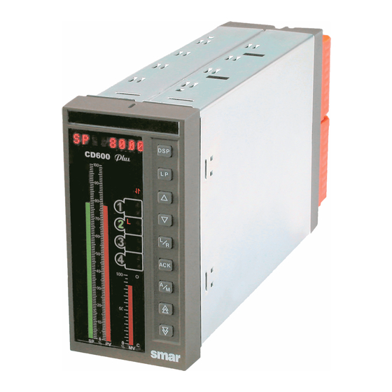
CD600 PLUS
Quick Installation Guide
This appendix is a summary for the user to install the CD600 Plus. It assumes that the user has
a previous knowledge about it.
This appendix informs:
• Which tools and equipments are necessary to install it;
• How to install it (electrically and mechanically);
Tools and Equipments necessary for the Installation
The items necessary for the installation are:
• Screwdriver;
• Cables for power supply;
• Cables for I/O signals;
• Cables for communication;
• ICS 2.0P interface for serial communication or ENET-710 for Ethernet.
Procedures
Check the content of the CD600 PLUS packing (See section 9 – Installation, in the
CD600 Plus Manual)
Check:
• The model that matches the ordering code;
• The equipment did not have any damage during transportation;
• The CD600 Plus manual, CD with configuration software and fixing clip to attach the
controller to the panel is inside the packing box according to the ordering code.
If some item of the code is not included, contact Smar Equipamentos Industriais Ltda.
Advertisement
Table of Contents

Related Manuals for SMAR CD600 PLUS


Summary of Contents for SMAR CD600 PLUS
- Page 1 CD600 PLUS Quick Installation Guide This appendix is a summary for the user to install the CD600 Plus. It assumes that the user has a previous knowledge about it. This appendix informs: • Which tools and equipments are necessary to install it;...
- Page 2 Mechanical Installation of the Controller The figure 1 shows the CD600 Plus Figure 2 shows the screwdriver and the inserted in the panel cut-out (front fixing clip bolt of the CD600 Plus (back view of the panel). view of the panel) Upper fixing clip...
- Page 3 Electrical Installation of the controller Figure 5 and 6 show the labels attached to the CD600 Plus side, AC and DC model, respectively. See through theirs legend the terminals meanings. Figure 5 – Side label with the terminal block diagram for the CD600 Plus AC model.
- Page 4 Connect the housing ground before supplying the equipment. Control strategy configuration Consult the CONF600 in the users manual for installing the configuration software. NOTE CD600 Plus is factory-configured to work with 4 loops. See in the CD600 Plus manual for more information about this subject.
- Page 5 Establishing the communication between the controller and the computer 1. Using the computer serial gate Connect the ICS 2.0P interface in the identified terminal in the label of the CD600 Plus with the specific cable. (See the ICS 2.0P manual for more details).
Need help?
Do you have a question about the CD600 PLUS and is the answer not in the manual?
Questions and answers