
Subscribe to Our Youtube Channel
Related Manuals for SMAR fy303


Summary of Contents for SMAR fy303
- Page 1 OPERATION, MAINTENANCE AND INSTRUCTION MANUAL Profibus PA Valve Positioner JUL / 16 F Y 3 0 3 M E...
- Page 2 Specifications and information are subject to change without notice. Up-to-date address information is available on our website. web: www.smar.com/contactus.asp...
- Page 3 Kpvtqfwevkqp" INTRODUCTION The FY303 is a Profibus PA valve positioner for Single (spring return) or Double acting Linear motion type control valves e. g. Globe, Gate, Diaphragm, Pinch or Clamp and Rotary motion type control valves e. g. Ball, Butterfly or Plug with pneumatic type actuators e. g. Diaphragm, Piston, Vane, or Bellows.
- Page 4 Smar provides specific training to instruct and qualify such professionals. However, each country must comply with the local safety procedures,...
-
Page 5: Table Of Contents
TRANSDUCER BLOCK SPECIFIC PARAMETER DESCRIPTIONS ............. 3.5 TRANSDUCER BLOCK PARAMETER ATTRIBUTE TABLE ................. 3.7 TRANSDUCER BLOCK VIEW OBJECT TABLE .................... 3.9 FY303 CYCLICAL CONFIGURATION ......................3.12 HOW TO CONFIGURE THE ANALOG OUTPUT BLOCK ................3.17 POSITION CALIBRATION ........................... 3.20 TEMPERATURE CALIBRATION ......................... 3.23 SELF-CALIBRATION ........................... - Page 6 H[525"/"Qrgtcvkqp."Ockpvgpcpeg"cpf"Kpuvtwevkqpu"Ocpwcn" ELECTRONIC CIRCUIT ..........................4.4 INTERCHANGEABILITY ..........................4.5 PACKAGE CONTENT ............................ 4.5 EXPLODED VIEW ............................4.6 SPARE PARTS LIST ............................4.7 DETAILED CODE WHEN ORDERING OF SPARE PARTS ................4.9 UGEVKQP"7"/"VGEJPKECN"EJCTCEVGTKUVKEU"0000000000000000000000000000000000000000000000000000000000000000000000000000000000"703 FUNCTIONAL SPECIFICATIONS ........................5.1 PERFORMANCE SPECIFICATIONS ......................5.2 PHYSICAL SPECIFICATIONS ........................5.2 ORDERING CODE ............................
- Page 7 Kpuvcnncvkqp"Hnqyejctv" Kpuvcnncvkqp"Hnqyejctv" XKK"...
- Page 8 H[525"/"Qrgtcvkqp."Ockpvgpcpeg"cpf"Kpuvtwevkqpu"Ocpwcn" XKKK"...
-
Page 9: General
For special supports, refer to specify instructions. After installing the support on the actuator, it is possible to mount the positioner FY303 on the support by means of the four screws with lock washers. Make sure that the arrow engraved on the magnet coincides with the arrow engraved on the positioner when the valve is in mid travel. -
Page 10: Pneumatic Connections
Air supply pressure to the FY303 shall be between 1.4 bar (20 psi) and 7 bar (100 psi). In case such requirements can not be fulfilled, the use of an air pressure regulator is acceptable. - Page 11 Installation Double Action - Air to Open (Fail Close) Connect Output 1 (OUT1) of the positioner to the input identified as OPEN in the actuator, and connect Output 2 (OUT2) of the positioner to the input CLOSE in the actuator. Double Action - Air to Close (Fail Open) Connect Output 2 (OUT2) of the positioner to the input identified as OPEN in the actuator, and connect Output 1 (OUT 1) of the positioner to the input CLOSE of the actuator.
- Page 12 FY303 - Operation, Maintenance and Instructions Manual REMOTE HALL SENSOR Figure 1.1 - FY303 Dimensional Drawing ROTATY ROTATY POSITIONER MAGNETY MAGNET BRACKET BRACKET M6x1 SCREWS VALVE STEM POSITIONER (4 PLACES) Figure 1.2 - Positioner on Rotary Actuator NOTE Included in the package content the centralizer device of rotary magnet. See figure 1.13.
- Page 13 Installation LINEAR MAGNET BRACKET VALVE YOKE POSITIONER BRACKET VALVE STEM M6x1 SCREWS (4 PLACES) LINEAR MAGNET CENTRALIZER DEVICE POSITIONER OUT 1 OUT 2 Figure 1.3 - Positioner on Linear Actuator NOTE Included in the package content the centralizer device of linear magnet. See figure 1.12.
-
Page 14: Electronic Housing Rotating
(See Figure 1.5). Figure 1.5 - Wiring Block The FY303 uses the 31.25 kbit/s voltage mode option for the physical signaling. All other devices on the same bus must use the same signaling. All devices are connected in parallel along the same pair of wires. -
Page 15: Topology And Network Configuration
Installation The FY303 is powered via the bus. The limit for such devices is according to the DP/PA coupler limitations for one bus for non-intrinsically safe requirement. In hazardous area, the number of devices may be limited by intrinsically safe restrictions, according to the coupler DP/PA and barriers limitations. -
Page 16: Intrinsic Safety Barrier
DP/PA coupler, when it is Non-Ex type. Use of SB302 is recommended. Jumper Configuration In order to work properly, the jumpers J1 and W1 located in the FY303 main board must be correctly configured. This jumper enables the simulation mode parameter in the AO block. -
Page 17: Power Supply
Installation Power Supply The FY303 receives power from the bus via the signal wiring. The power supply may come from a separate unit or from another device such as a controller or DCS. The voltage should be between 9 to 32 Vdc for non-intrinsic safe applications. -
Page 18: Rotary And Linear Magnet
FY303 - Operation, Maintenance and Instructions Manual OIL AND WATER DRY AIR MIST PREFILTER DRYER AFTERFILTER WITH DRAIN Figure 1.10 - Air Quality Conditioning System Rotary and Linear Magnet Magnet models are linear and rotary, for utilization on linear and rotary actuators. - Page 19 Therefore, when installing the cable inside the conduit (maximum limit 20 meters length) keep it away from possible sources of induction and/or magnetic interference. The cable supplied by Smar is shielded for excellent protection against electromagnetic interference, but despite this protection avoid the cable sharing the same conduit with other cables.
- Page 20 FY303 - Operation, Maintenance and Instructions Manual 1.12...
-
Page 21: Functional Description - Output Module
Section 2 OPERATION Functional Description - Output Module The main parts of the output module are the pilot, servo, Hall Effect sensor and the output control circuit. The control circuit receives a digital setpoint signal from the CPU and a feedback signal from the Hall Effect sensor. -
Page 22: Functional Description-Electronics
FY303 – Operation, Maintenance and Instructions Manual Functional Description-Electronics Refer to the block diagram. The function of each block is described below. Figure 2.2 - FY303 Block Diagram... - Page 23 Operation Receives the signal from the CPU and converts it to an analog voltage proportional the desired position, used by the control. Control Controls the valve position according to the data received from the CPU and the Hall effect sensor feedback.
-
Page 24: Introduction To Fieldbus Application
FY303 – Operation, Maintenance and Instructions Manual Introduction to Fieldbus Application From a Fieldbus point of view, the FY303 is not an assembly of electronics, housing and sensor forming a positioner, but a network node containing function blocks. Basically, it contains one output transducer block, one resource block, one display transducer block and Analog Output block. - Page 25 VARIABLE / MODE UNIT AND FUNCTION FIELD Figure 2.3 - Local Indicator Upon receiving power, the FY303 initializes the position indication on the display, by showing model FY303 and its software version (X.XX). Monitoring During normal operation, FY303 remains in the monitoring mode. The display simultaneously shows readout and some other information.
- Page 26 FY303 – Operation, Maintenance and Instructions Manual...
-
Page 27: Transducer Block
For explanation and details of function blocks, see the “Function Blocks Manual”. The 303 Smar family is integrated in Simatic PDM, from Siemens. It is possible to integrate any 303 Smar devices into any configuration tool for Profibus PA devices. It is necessary to provide a Device Description or Drive according to the configuration tool. -
Page 28: Functional Diagram Of The Positioner Transducer Block
FY303 – Operation, Maintenance and Instructions Manual Functional Diagram of the Positioner Transducer Block Figure 3.1 - Functional Diagram of the Positioner Transducer Block... -
Page 29: Transducer Block Standard Parameter Descriptions
10 = reset internal control loop disturbed“ CB_CONTR_ERR (optional) SELF_CALIB_CMD 255 = abort current calibration-procedure (optional) Smar: 0 = default value; no reaction of the field device 2 = start self calibration / initialization 7 = reset total valve travel 255 = abort current calibration-procedure Proportional-action coefficient for both moving directions. - Page 30 FY303 – Operation, Maintenance and Instructions Manual Parameter Transducer Block Description The X_Y_VALUE parameter contains one value couple of the table TAB_X_Y_VALUE For device internal reasons (e.g. for calculation), sometimes it is necessary to use a certain number of table TAB_MIN_NUMBER values in minimum.
-
Page 31: Transducer Block Specific Parameter Descriptions
Configuration Transducer Block Specific Parameter Descriptions Parameter Transducer Block Description Air to Open/Close. AIR_TO {0, "Open"}, {1, "Close"} CAL_POINT_HI The highest calibrated point. The lowest calibrated point. CAL_POINT_LO CAL_MIN_SPAN The minimum calibration span value allowed Engineering units code for the calibration values, %(1342). CAL_UNIT FEEDBACK_CAL The position value used to correct a calibration. - Page 32 FY303 – Operation, Maintenance and Instructions Manual Parameter Transducer Block Description Indicates the status of diagnoses: { 0, "None"}, { 2, "Output Module Not Initialized"}, { 4, "No Valve Movement or Slow Valve Movement or Low Air Supply or No Magnet Detected"}, { 6, "(No Valve Movement or Slow Valve Movement or Low Air Supply or No Magnet Detected)
-
Page 33: Transducer Block Parameter Attribute Table
Configuration Parameter Transducer Block Description Indicates the condition of calibration process according to: { 16, "Default value set"}, {22, "Applied process out of range"}, XD_ERROR {26, "Invalid configuration for request"}, {27, "Excess correction"}, {28, "Calibration failed"} MAIN_BOARD_SN THE ELECTRONIC MAIN BOARD SERIAL NUMBER. This parameter is used to indicate EEPROM saving process. - Page 34 FY303 – Operation, Maintenance and Instructions Manual Parameter Mandatory/ Relative Object usage/ Parameter Name Data Type Store Size Access Default Optional Index Type Type of (Class) Transport TRAVEL_RATE_INC Simple Float VALVE_MAINT_DATE Simple Octet String SERVO_GAIN_2 Simple Float SERVO_RATE_2 Simple Float...
-
Page 35: Transducer Block View Object Table
Configuration Parameter Mandatory/ Relative Object usage/ Parameter Name Data Type Store Size Access Default Optional Index Type Type of (Class) Transport MAX_RANGE_VALVE simple float HIGHEST_TEMPERATURE simple float LOWEST_TEMPERATURE simple float DIAGNOSES_STATUS simple Unsigned8 None DIGITAL_HALL_VALUE Record DS-33 HALL_COMPENSATED simple float HALL_OFFSET_CONTROL simple Unsigned8... - Page 36 FY303 – Operation, Maintenance and Instructions Manual Relative Index Parameter Name VIEW_1 Number of bytes TRAVEL_LIMIT_LOW TRAVEL_LIMIT_UP TRAVEL_RATE_DEC TRAVEL_RATE_INC VALVE_MAINT_DATE SERVO_GAIN_2 SERVO_RATE_2 SERVO_RESET_2 TAB_OP_CODE TAB_STATUS POSITIONING_VALUE FEEDBACK_VALUE VALVE_MAN ACTUATOR_MAN VALVE_TYPE ACTUATOR_TYPE ACTUATOR_ACTION VALVE_SER_NUM ACTUATOR_SER_NUM ADD_GEAR_SER_NUM ADD_GEAR_MAN ADD_GEAR_ID ADD_GEAR_INST_DATE AIR_TO CAL_POINT_HI...
- Page 37 Configuration Relative Index Parameter Name VIEW_1 Number of bytes TIME_OPENING MAX_RANGE_VALVE HIGHEST_TEMPERATURE LOWEST_TEMPERATURE DIAGNOSES_STATUS DIGITAL_HALL_VALUE HALL_COMPESATED HALL_OFFSET_CONTROL READ_HALL_CAL_POINT_HI READ_HALL_CAL_POINT_LO DA_OUTPUT_VALUE USER_DA_CAL_POINT_HI USER_DA_CAL_POINT_LO PIEZO_ANALOG_VOLTAGE POT_DC MAIN_LATCH XD_ERROR MAIN_BOARD_SN EEPROM_FLAG ORDERING_CODE Total length of View Object Table 3.4 - View Object Table Transducer Block 3.11...
-
Page 38: Fy303 Cyclical Configuration
FY303 has one AO function block. It is with this block that the class 1 master will execute the cyclical services and the user should choose the configuration, according to the application. - Page 39 Auto Setup procedure for FY303 positioner in ACP. When the positioner FY303 is working with a pneumatic cylindrical actuator or a valve with high air inertia (slow movement) and during the self calibration process (SETUP) is gotten 40% permanently on the LCD, please decrease the ACP_F value using the local adjustment.
- Page 40 Figure 3.2 - Offline Configuration - Transducer Selecting the page Setup, the user configures some data for the internal servo PID of FY303. Configurable seconds to full span change (closing time of the valve) in...
- Page 41 Configuration Table handling There is the possibility to load and re-load tables in the devices. This table is used for linearization mostly. For this procedure the following parameters are necessary: TAB_INDEX TAB_X_Y_VALUE TAB_MIN_NUMBER TAB_MAX_NUMBER TAB_OP_CODE TAB_STATUS The TAB_X_Y_VALUE parameter contains the value couple of the each table entries. To make the configuration of Transducer Block, we need to select the menu Device - Offline Configuration -Transducer.
- Page 42 Figure 3.5 - FY303 Simatic PDM - Transducer Offline Configuration - User Table Screen The desired flow characteristics may be changed using this function. E.g. If a valve with linear inherent flow characteristic is used and equal percentage applied flow characteristic is selected, the valve will be act as an equal percentage valve.
-
Page 43: How To Configure The Analog Output Block
The user needs to set both channel to transducer. The user can set opening or closing for the actuator action. Figure 3.6 - FY303 Simatic PDM - Analog Output Block - Basic Settings - Offline Configuration 3.17... - Page 44 Selecting the page Scale/Units, the user has the option to configure the scale and unit for the input and output: Figure 3.7 - FY303 Simatic PDM - Analog Output Block - Scale/Units - Offline Configuration The unit and scale for the output will be the same for the transducer block. Note that the allowed units are %, rad, °, mm.
- Page 45 Figure 3.9 - FY303 Simatic PDM - Online Configuration Mode Block for AO Using Feedback page, the user can monitor and check all values related between the analog block and the transducer block:...
-
Page 46: Position Calibration
To start the lower calibration procedure. Figure 3.11 - FY303 - Simatic PDM Calibration Lower/Upper After pressing "Lower Calibration Point", we get a warning: If the user proceeds, the valve position goes to the lower position and we have the message: If the valve is stabilized, when the user press "OK", we have a new window that allows him to enter... - Page 47 Configuration After entering the desired valve, the position is corrected according to the desired value and the user can make the correction until the right position is reached: If the calibrated position is correct, press "No" and a new warning appears: After user confirmation, the positioner comes to the normal operation.
- Page 48 FY303 – Operation, Maintenance and Instructions Manual If the user proceeds, the valve position goes to the upper position and we have the message: If the valve is stabilized, when the user press "OK", we have a new window that allows him to enter the desired value for the new calibrated point for the upper position.
-
Page 49: Temperature Calibration
Using the Simatic PDM, go to the Device menu and select the "Calibration" menu and then "Temperature: The user can set the desired calibration temperature point. Here, the final calibrated temperature can be checked. The user can check the operation result. To calibrate, press the key "write". Figure 3.12 - FY303 Temperature Calibration 3.23... -
Page 50: Self-Calibration
FY303 – Operation, Maintenance and Instructions Manual Self-Calibration Using the "Self-Calibration" procedure, the user starts a method of self-calibration for the positioner. For this reason, the option "Start self calibration/Initialization" should be selected at the window below. The self-calibration can take some minutes according to the valve:... -
Page 51: Diagnosis
The value for the DA converter and the calibrated points for it. Figure 3.13 - FY303 Maintenance Self-Calibration Report Diagnosis Using the "View" menu and selecting "Diagnosis", the user has accessing to the diagnosis windows, according to the window below:... -
Page 52: Transducer Display - Configuration
FY303 – Operation, Maintenance and Instructions Manual Selecting the "Diagnosis" page, we have: Figure 3.15 - FY303 Diagnosis Using this window, the user can have some items for diagnosing: Travel: according to the maximum range valve value, we have the total valve travel and a generation of traveling Limit Exceeded when this value is higher than limit total valve travel parameter;... -
Page 53: Display Transducer Block
Adjustment". It is significantly the resources on this transducer display, also all the Series 303 field devices from Smar has the same methodology to handle with it. So, since the user has learned once, he is capable to handle all kind of field devices from Smar. -
Page 54: Definition Of Parameters And Values
FY303 – Operation, Maintenance and Instructions Manual Definition of Parameters and Values Select Block Type This is the type of the block where the parameter is located. The user can choose: Transducer Block, Analog Output Block, Physical Block or None. - Page 55 Configuration The window "Local Address Change" allows the user "enable/disable” access to changing the physical device address. When the option "enable" is selected, the user can change the physical device address. Figure 3.18 - Parameters for Local Address Configuration When the user enter into the local adjustment and rotate the parameters using the magnetic tool, after escaping to normal operation, e.g., the monitoring, if the parameter when the magnetic tool is removed has "Access Permission equal to "monitoring", then this last parameter will be shown at the LCD.
-
Page 56: Calibrating Using Local Adjustment
FY303 – Operation, Maintenance and Instructions Manual The user can select the "Mode Block" parameter at the LCD. In this case is necessary to select the index equal to "Mode Block": With this option, the Mode Block parameter is shown at the LCD. - Page 57 S and wait tool in orifice Z and during 5 seconds. wait until letters MD are displayed. Figure 3.23 - Step 1 - FY303 Remove the Insert the magnetic tool in orifice S magnetic tool from orifice S.
- Page 58 FY303 – Operation, Maintenance and Instructions Manual Place the magnetic In this option TYPE, tool in orifice Z. In is indicated by the case this is the first numbers 1 or 2, configuration, the which respectively option shown on the...
- Page 59 LOPOS as well as position valve. UPPOS. An arrow pointing upward increments the position valve. Figure 3.28 - Step 6 - FY303 Insert the magnetic This option tool in orifice S and implements the enter the value 2. auto setup of the...
-
Page 60: Self-Calibration Using Local Adjustment
This operation can be done using the Configuration Tool or the Local Adjustment. The FY303 automatically finds the fully open and closed positions of a valve, but the user may also set a narrower range of operation should he like to. Before making the Auto-Setup, select the type of valve through the parameter VALVE_TYPE choosing between "Linear or Rotary"... -
Page 61: Temperature Compensation
Configuration Temperature Compensation Using the Calibration Temperature Menu at the Device, the user can trim the temperature sensor located at the body of positioner in order to improve the accuracy of temperature measurement done by its sensor. The range accepts from -40°C to +85 °C. The temperature parameter indicates the value of such measurement. -
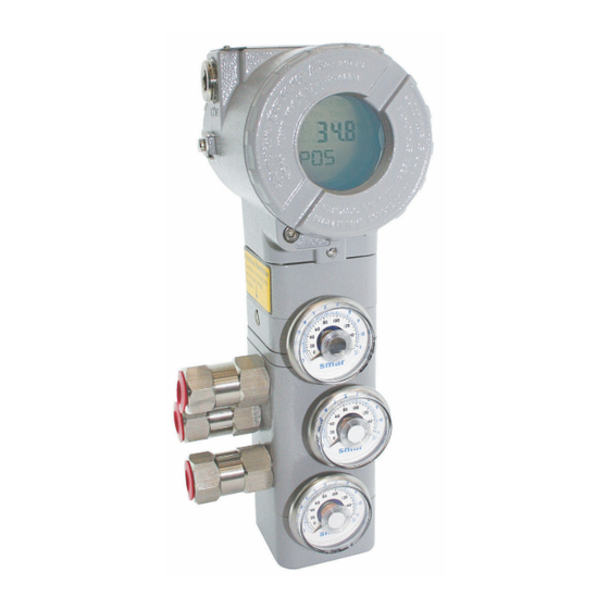
Page 62: Pressure Sensors Version (K1 Option)
FY303 – Operation, Maintenance and Instructions Manual Pressure Sensors Version (K1 Option) The K1 option of the FY303 is available with 3 pressure sensors, namely one for input and two for both outputs. How to check the pressure sensors installation In terms of configuration, after identifying the presence of the sensors on the hardware, their installation may be checked via Simatic PDM. - Page 63 Configuration Figure 2 – Pressure Sensors Calibration Next step is selecting which sensor is to be calibrated: if the input (Press In), or the output 1 (Out 1), or the output 2 (Out 2). See figure 3. 3.37...
- Page 64 FY303 – Operation, Maintenance and Instructions Manual Figure 3 – Selecting the Sensors for Pressure Calibration Figure 4 – Upper Pressure Point Calibration 3.38...
- Page 65 Sensor Cal Point Hi and Sensor Cal Point Lo, watching on the window bottom the values read by the FY303. Figure 5 – Lower Pressure Point Calibration FY303 Performance Graph Go the “View”...
- Page 66 FY303 – Operation, Maintenance and Instructions Manual Figure 6 – FY303 Graph Selection When choosing “Position Performance Diagram”, the PDM will show the respective graph, as on figure 7, where the user may watch the behavior of the real valve position on the SetPoint throughout the action.
- Page 67 Configuration Figure 7 – Real Position x SP Clicking on the scales, the user may adjust them at his discretion and, in addition, zoom in the curve to locate a specific area. Figure 8 – Scale adjustment 3.41...
- Page 68 FY303 – Operation, Maintenance and Instructions Manual By choosing “Pressure Diagram”, the real position may be drawn by the sensor selected on figure 3, as shown on figure 9. If no sensor was selected, the “Pressure Diagram” option will not be seen on the “View”...
- Page 69 Configuration Figure 10 – Sensor Pressure Configuration Data 3.43...
- Page 70 FY303 – Operation, Maintenance and Instructions Manual 3.44...
-
Page 71: General
Try spare parts in the positioner circuits. Pressure Output Connections Check up on air leaks. Air Supply Pressure Check the air supply pressure. The input pressure to FY303 shall be between 20 psi and 100 psi. NO RESPONSE TO INPUT SIGNAL Calibration Check the positioner calibration points. -
Page 72: Disassembly Procedure
FY303 – Operation, Maintenance and Instructions Manual NOTE The Factory Init should be tried as a last option to recover the equipment control when the equipment presents some problem related to the function blocks or the communication. This operation must only be carried out by authorized technical personnel and with the process offline, since the equipment will be configured with standard and factory data. -
Page 73: Reassembly Procedure
Maintenance Procedures ELECTRONIC CIRCUIT To remove the circuit board (5) and indicator (4), first loose the cover locking (13) on the side not marked “Field Terminals”, then unscrew the cover (1). WARNING The boards have CMOS components, which may be damaged by electrostatic discharges. Observe correct procedures for handling CMOS components. -
Page 74: Change Of The Filter Elements
FY303 – Operation, Maintenance and Instructions Manual Remove the o-ring’s with an appropriate tool; Dive the part in petroleum base solvent and dry it with compressed air (apply the compressed air directly in the smaller orifice for the air to get out through the bigger orifice). -
Page 75: Interchangeability
The plug must obligatorily be installed in the electric connection not used, preventing the humidity entrance. WARNING The standard plug provided with Smar positioner do not have an EExd certification. Interchangeability Main board can be changed and operate with the transducer. There is an EEPROM in the transducer part that keeps the trim. - Page 76 H[525"⁄"Qrgtcvkqp."Ockpvgpcpeg"cpf"Kpuvtwevkqpu"Ocpwcn" Gzrnqfgf"Xkgy" Hkiwtg"605"/"Gzrnqfgf"Xkgy" 608"...
-
Page 77: Spare Parts List
Ockpvgpcpeg"Rtqegfwtgu" " Urctg"Rctvu"Nkuv" SPARE PARTS LIST CATEGORY PARTS DESCRIPTION POSITION CÓDE (NOTE 4) HOUSING (NOTE 1) 400-1314-3P (NOTE 6) COVER (INCLUDES O-RING) 1 and 13 400-1307 (NOTE 6) Cover Locking Bolt 204-0120 Sensor Locking Bolt (M6 Without Head Screw) 400-1121 External Ground Bolt 204-0124 Identification Plate Fixing Bolt... - Page 78 H[525"⁄"Qrgtcvkqp."Ockpvgpcpeg"cpf"Kpuvtwevkqpu"Ocpwcn" SPARE PARTS LIST CATEGORY PARTS DESCRIPTION POSITION CÓDE (NOTE 4) 400-0808 1/2" NPT (Ex d) INTERNAL SOCKET SET PLUG IN BICHROMATIZED CARBON STEEL 400-0809 1/2" NPT (Ex d) INTERNAL SOCKET SET PLUG IN 304 SST 1/2" NPT INTERNAL SOCKET SET PLUG IN BICHROMATIZED CARBON 400-0583-11 STEEL 1/2"...
-
Page 79: Detailed Code When Ordering Of Spare Parts
Ockpvgpcpeg"Rtqegfwtgu" Fgvckngf"Eqfg"Yjgp"Qtfgtkpi"qh"Urctg"Rctvu" DETAILED CODE WHEN ORDERING OF SPARE PARTS CÓDE DESCRIPTION 400-1314-3P HOUSING; FY303 Option Electrical Connection ½ NPT M20 X 1,5 PG13,5 Option Material Aluminum (IP/Type) Stainless Steel (IP/Type) Aluminum - for saline atmospheres (IPW/Type X) Aluminum Copper Free (IPW/Type X) - Page 80 Stainless Steel (IP/TYPE) Option Painting Gray Munsell N 6,5 Without Painting Safety Blue Epoxy - Electrostatic Painting Option Standard of Manufacture Smar Option Hall Remote Sensor Standard Mounting (Without Hall Remote Sensor) Remote Mounting (adapted for Remote Sensor) Option Special Sensor...
- Page 81 Stainless Steel (IP/TYPE) Option Painting Gray Munsell N 6,5 Without Painting Safety Blue Epoxy - Electrostatic Painting Option Standard of Manufacture Smar 400-1318 TYPICAL ORDERING CODE * Choose the desired option. DETAILED CODE WHEN ORDERING OF SPARE PARTS CÓDE DESCRIPTION 400-1319 Hall Cover Set;...
- Page 82 Stainless Steel (IP/TYPE) Option Painting Gray Munsell N 6,5 Without Painting Safety Blue Epoxy - Electrostatic Painting Option Standard of Manufacture Smar 400-1321 TYPICAL ORDERING CODE * Choose the desired option. DETAILED CODE WHEN ORDERING OF SPARE PARTS CÓDE DESCRIPTION 400-1322 Remote Extension Set;...
-
Page 83: Functional Specifications
Section 5 TECHNICAL CHARACTERISTICS Functional Specifications Travel Linear Motion: 3 - 100 mm. Rotary Motion: 30 - 120° Input Signal Digital only. Fieldbus, 31.25 kbits/s voltage mode with bus power. Output Output to actuator 0 -100% supply air pressure. Single or double-action. Power Supply Bus powered: 9-32 Vdc. -
Page 84: Performance Specifications
FY303 – Operation, Maintenance and Instructions Manual Performance Specifications Resolution ≤ 0.1% F.S. Repeatability ≤ 0.1% F.S. Hysteresis ≤ 0.1% F.S. Consumption 0.35 Nm/h (0.20 SCFM) at 1.4 bar (20 psi) supply. 1.10 Nm/h (1.65 SCFM) at 5.6 bar (80 psi) supply. - Page 85 Leave it blank for no optional items. NOTES (1) Consult Smar for applications in classified areas. (5) Certificate for use in Hazardous Locations (CEPEL, FM, CSA). (2) IPW/TYPEX tested for 200 hours according to NBR 8094 / ASTM B 117 standard.
- Page 86 TYPICAL MODEL NUMBER * Leave it blank for no optional item. ** For customized mounting bracket, for different brands and models, please, consult www.smar.com . When choosing the remote sensor version, an additional “L” shape bracket is included, for 2” tube mounting.
- Page 87 Technical Characteristics...
- Page 88 FY303 – Operation, Maintenance and Instructions Manual...
- Page 89 Crrgpfkz"C " CERTIFICATIONS INFORMATION Gwtqrgcp"Fktgevkxg"Kphqtocvkqp" Consult www.smar.com for the EC declarations of conformity for all applicable European directives and certificates. ATEX Directive (94/9/EC) – “Electrical equipment and protective system intended for use in potential explosive atmospheres” The EC-Type Examination Certificate had been released by Nemko AS (CE0470) and/or DEKRA EXAM GmbH (CE0158), according to European Standards.
-
Page 90: Csa (Canadian Standards Association)
Entity parameters at terminals “+” and “-”: Vmax = 24 V, Imax = 250 mA, Pmax = 5.32 W, Ci = 5 nF, Li = 12 uH, when connected as per Smar Installation Drawing 102A0836; T Code T3C @ Max Ambient 40 Deg C; MWP 100 psi. -
Page 91: Nemko (Norges Elektriske Materielkontroll)
Egtvkhkecvkqpu"Kphqtocvkqp" Non Incendive (FM 3D9A2.AX and 3015629) NI Class I, Division 2, Groups A, B, C and D Environmental Protection (FM 3007267, 3D9A2.AX and 3015629) Option: Type 4X or Type 4 Special conditions for safe use: Entity Parameters Fieldbus Power Supply Input (report 3015629): Vmax = 24 Vdc, Imax = 250 mA, Pi = 1.2 W, Ci = 5 nF, Li = 12 uH Vmax = 16 Vdc, Imax = 250 mA, Pi = 2 W, Ci = 5 nF, Li = 12 uH Temperature Class T4... - Page 92 H[525"⁄"Qrgtcvkqp."Ockpvgpcpeg"cpf"Kpuvtwevkqpu"Ocpwcn" Protection by enclosure (CEPEL 00.0017) Ex tb, Group IIIC, Temperature Class T135ºC/T100ºC/T85ºC, EPL Db Ambient Temperature: -20 to 65 ºC for T135ºC -20 to 50 ºC for T100ºC -20 to 40 ºC for T85ºC Explosion Proof (CEPEL 98.0008) Ex d, Group IIC, Temperature Class T6, EPL Gb Maximum Ambient Temperature: 40ºC (-20 to 40 ºC) Protection by enclosure (CEPEL 98.0008) Ex tb, Group IIIC, Temperature Class T85ºC, EPL Db...
- Page 93 Egtvkhkecvkqpu"Kphqtocvkqp" Kfgpvkhkecvkqp"Rncvg"" CSA (Canadian Standards Association) FM Approvals (Factory Mutual) NEMKO (Norges Elektriske MaterielKontroll) / EXAM (BBG Prüf - und Zertifizier GmbH) CEPEL (Centro de Pesquisa de Energia Elétrica) C07"...
- Page 94 H[525"⁄"Qrgtcvkqp."Ockpvgpcpeg"cpf"Kpuvtwevkqpu"Ocpwcn" C08"...
- Page 95 Egtvkhkecvkqpu"Kphqtocvkqp" Eqpvtqn"Ftcykpi" FM Approvals (Factory Mutual) C09"...
- Page 96 H[525"⁄"Qrgtcvkqp."Ockpvgpcpeg"cpf"Kpuvtwevkqpu"Ocpwcn" CSA (Canadian Standards Association) C0:"...
- Page 97 Egtvkhkecvkqpu"Kphqtocvkqp" C0;"...
- Page 98 H[525"⁄"Qrgtcvkqp."Ockpvgpcpeg"cpf"Kpuvtwevkqpu"Ocpwcn" C032"...
- Page 99 Company: _____________________________________________________________________________________________________ Contact: ______________________________________________________________________________________________________ Title: _________________________________________________________________________________________________________ Section: ______________________________________________________________________________________________________ Phone: __________ _________________________ __________ _________________________ Extension:____________________ E-mail: _________________________________________________________________________ Date: ______/ ______/ __________ For warranty or non-warranty repair, please contact your representative. Further information about address and contacts can be found on www.smar.com/contactus.asp. D03"...
- Page 100 H[525"⁄"Qrgtcvkqp."Ockpvgpcpeg"cpf"Kpuvtwevkqpu"Ocpwcn" Tgvwtpkpi"Ocvgtkcnu" Should it become necessary to return the positioner and/or configurator to SMAR, simply contact our office, informing the defective instrument serial number, and return it to our factory. In order to speed up analysis and solution of the problem, the defective item should be returned with a description of the failure observed, with as much details as possible.
- Page 101 Crrgpfkz"E" SMAR WARRANTY CERTIFICATE SMAR guarantees its products for a period of 24 (twenty four) months, starting on the day of issuance of the invoice. The guarantee is valid regardless of the day that the product was installed. SMAR products are guaranteed against any defect originating from manufacturing, mounting,...
- Page 102 13. It is the customer’s responsibility to clean and decontaminate products and accessories prior to shipping them for repair, and SMAR and its dealer reserve themselves the right to refuse the service in cases not compliant to those conditions. It is the customer’s responsibility to tell SMAR and its dealer when the product was utilized in applications that contaminate the equipment with harmful products during its handling and repair.
- Page 103 APPENDIX MOUNTING BRACKET FOR POSITIONER – LINEAR STROKE VALVE MOUNTING INSTRUCTIONS 1 –Attach the magnet to the magnet bracket support before connect them to the valve stem. 2 - The stem nuts should be used to fasten the magnet bracket. 3 –...
- Page 104 Mounting Instructions 4 – Tighten the hex screw that join the two parts of the magnet bracket. It will avoid sliding of the two parts of the bracket during the fastening of the stem nuts. 5 – Tighten the stem nuts. 6 –...
- Page 105 BFY – MOUNTING BRACKET FOR POSITIONER FY 7 – Adjust the clamps according to the width of the yoke and tighten the bolts finger tight. 8 – Mount the positioner back plate. Tighten the nuts finger tight. 9 – Use the plate as a guidance to adjust the position of the positioner so that the back plate is about 1 mm apart from the magnet.
- Page 106 Mounting Instructions 10 – Fasten the nuts to fix the positioner bracket to the yoke. If the actuator is pillar type, fasten the U- clamp nuts. 11 – Mount the positioner to the plate and tighten the hex screws. You can take the back plate apart to facilitate the assembling.
- Page 107 BFY – MOUNTING BRACKET FOR POSITIONER FY 13 – Put the pressure equivalent to the half of the stem travel and adjust the height of the bracket assembly to have the arrows matching. 14 - Tighten the bolts to fasten the clamps to the yoke.
- Page 108 Mounting Instructions MOUNTING DETAILS FOR THE PILLAR TYPE ACTUATOR 15 - This is the mounting bracket using U- clamps to be mounted on pillar type actuators. 16 – After assembling the U-clamps, follow the steps 8 to 13.
- Page 109 ROTARY VALVE POSITIONER BRACKET MOUNTING INSTRUCTIONS Rotary Valve Positioner Bracket Parts. 1- Attach the clamps to the threaded orifices existent on the actuator. Do not tight them completely. The bolts are not supplied with the mounting bracket and they must be in accordance with size and thread of the actuator holes.
- Page 110 Mounting Instructions 3 – Fasten the hex screw. 4 – Attach the magnet to the NAMUR adapter. Do not fasten the bolts completely, allowing the magnet rotation. 5 – Mounting the positioner bracket through the threaded rods.
- Page 111 BFY – MOUNTING BRACKET FOR POSITIONER FY 6 – Use the centralizer gadget to get the bracket centralized with the magnet. 7 – Adjust the positioner bracket using the centralizer gadget and the nuts to get the height. 8 – Place the nut and washers. Do not fasten the nuts completely.
- Page 112 Mounting Instructions 9 – Tighten the clamp bolts to fasten them to the actuator. 10 – Fasten the positioner bracket bolts to the clamps fastening. 11 – Remove the centralizer gadget and fasten the positioner to the positioner bracket.
- Page 113 BFY – MOUNTING BRACKET FOR POSITIONER FY 12 – Put the pressure equivalent to the half of the stem and adjust the magnet position to have the arrows matching. 13 – Tighten the bolts to fasten the magnet to the magnet bracket.
- Page 114 Mounting Instructions...
Need help?
Do you have a question about the fy303 and is the answer not in the manual?
Questions and answers