Table of Contents
Advertisement
Quick Links
Advertisement
Table of Contents

Related Manuals for SMAR LC700


Summary of Contents for SMAR LC700
- Page 2 Specifications and information are subject to change without notice. Up-to-date address information is available on our website. web: www.smar.com/contactus.asp...
- Page 3 Maintanance Precautions MAINTENANCE PRECAUTIONS Attention: Electrostatic discharges may damage semiconductor eletronic devices if they are handled or if their module connector pins of racks and modules are handled. It is recommended that: Unload an electrostatic load touching objects that are grounded before handling the modules and racks.
- Page 4 LC700 – User’s Guide...
- Page 5 PID controller and the first commercial line with Fieldbus products for process automation are examples of the pioneering achievements of Smar. The LC700 now joins the family of Smar products building the bridge between process and manufacturing automation. This LC700 operates with the configurator (CONF700) which is software based on Windows.
- Page 6 LC700 – User’s Guide...
-
Page 7: Table Of Contents
CHAPTER 2 - LC700 ARCHITECTURE ......................2.1 RACKS AND MODULES ............................2.1 BASIC COMPONENTS ..............................2.1 RACKS, CABLES AND ACCESSORIES OF LC700 SYSTEM ................2.2 INSTALLING THE SYSTEM’S BASE WITH DF93 RACKS ..................2.2 INSTALLING RACKS - DF93............................2.3 INSTALLING THE EXPANSION FLAT CABLES - DF101, DF102, DF103, DF104 AND DF105........2.5 FLAT CABLES PROTECTOR (CONNECTOR CAP)......................2.6... - Page 8 LC700 – User’s Guide COMMUNICATION CHANNELS ............................3.27 DEVICE COMMUNICATION BAUD RATE AND DEVICE ADDRESS ................3.29 CPU-700 OPERATION MODES .............................3.29 CPU-700-E3R - REDUNDANT CPU MODULE ....................3.31 TERMINOLOGY AND INITIAL DESCRIPTIONS ......................3.31 ARCHITECTURE................................3.33 POWER –UP PROCEDURE............................3.34 COMMUNICATION WITH REMOTE I/O MODULES ......................3.34 TECHNICAL SPECIFICATIONS.............................3.35...
- Page 9 ENET-700 - MODBUS/TCP 10 BASE-T ETHERNET MODULE ................3.97 DESCRIPTION ................................3.97 TECHNICAL SPECIFICATIONS.............................3.98 LED STATUS DISPLAY..............................3.98 SETTING THE ENET-700 ..............................3.99 SETTING THE ENET-700 ON LC700..........................3.99 ENET-710 – MODBUS/CDBUS TCP 10/100 BASE-T ETHERNET MODULE ........... 3.101 DESCRIPTION ................................3.101 TECHNICAL SPECIFICATIONS...........................3.101 PROCEDURE TO REPLACE THE ENET-700 FOR ENET-710 ...................3.102 SW-700 –...
- Page 10 LC700 – User’s Guide APPENDIX ..............................A.1 RETURNING MATERIALS .............................A.1 FSR – SERVICE REQUEST FORM ........................A.2...
-
Page 11: Chapter 1 - Overview Of A Lc700 System
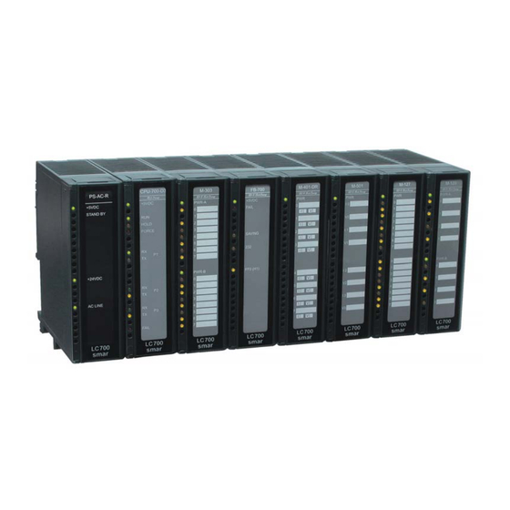
The LC700 is able to deal with a total of 2000(*) discrete points, 1024 analog variables and carries a large list of function blocks from the most standard instructions to more sophisticated ones for process control. - Page 12 LC700 – User’s Guide DIN RAIL PS-AC-R POWER SUPPLY RACK MODULES Figure 1.2 - CPU Figure 1.3– Picture of a LC700 System...
-
Page 13: Chapter 2 - Lc700 Architecture
Rack makes room for four (4) extra Modules (See Figure 2.1). Figure 2.1 - Racks and Modules One LC700 system can have up to fifteen (15) Racks. This implies a maximum of sixty (60) Modules per system. This section provides instructions on how to build an LC700 system. The next topic will describe the basic components of an LC700 system and how to install them. -
Page 14: Racks, Cables And Accessories Of Lc700 System
LC700 – User’s Guide Racks, cables and accessories of LC700 system Código Descrição M-000 Blind module to fill empty slots R-700-4A Rack with 4 slots - support to shielded flat cable T-700 Terminator for last the rack – right side FC-700-0 Flat Cable to connect 2 racks (6.5 cm) -
Page 15: Installing Racks - Df93
LC700 Architecture C – DF90 cable – Cable for IMB power transmission. In this cable is the Vcc and GND of IMB and it has to be connected in the rack’s left side. D – Module support - Module holder located in the top of the rack. - Page 16 LC700 – User’s Guide IMPORTANT Remember to leave a space in the DIN rail to install the DF91 and the grounding terminal at rack’s left side. Installing racks in the DIN rail IMPORTANT Before installing the rack on DIN rail, connect the flat cable to rear’s connector (E) if you will connect this rack to another at left.
-
Page 17: Installing The Expansion Flat Cables - Df101, Df102, Df103, Df104 And Df105
Installing the expansion flat cables - DF101, DF102, DF103, DF104 and DF105. These flat cables are used when the LC700 is expanded in more than one row of racks, i.e., in different DIN rail segments, one below the other. DF101 - Flat cable to connect racks by left side It is installed in the rack’s rear connectors (E) of the left extremity of each row of racks,... -
Page 18: Flat Cables Protector (Connector Cap)
LC700 – User’s Guide Figure 2.8 - Ground terminal installed Flat cables protector (connector cap) To meet the EMC requirements a protector against ESD has to be installed on the flat cables connection, at right. In the following figure a flat cable protector is shown when it is being installed on the cable connector. - Page 19 LC700 Architecture T-700 – IMB terminator for right side It is connected to connector N of the last rack, when it is connected to the others by the left side. See the next figure. Figura 2.11 – T-700 terminator installed in the rack Installation Follow the pictures below to install correctly the T700.
-
Page 20: Expanding The System's Power - Df90 And Df91
Expanding the system’s power - DF90 and DF91 This expansion has to be used when the LC700 is expanded in more than one row of racks, i.e., in different DIN rail segments, one below the other. - Page 21 LC700 Architecture Figure 2.15 Example of expanded system IMPORTANT The DF91 must be installed at left side of each row of racks, to meet the requeriments of EMC standards even if no expansion of power. Installing the DF91 in the DIN rail The DF91 is installed on the rack of the left extremity of each row of racks.
- Page 22 LC700 – User’s Guide Figure 2.16 DF91 rear part Connecting the DF91 to rack The first rack’s slot needs to be empty allowing access to this operation. Loose the screws (only the sufficient) of the rack’s power connector. See the next figure.
- Page 23 LC700 Architecture Installing DF90 Figure 2.19 - IMB power cable (DF90) The cable DF90 must be connected only through DF91, interconnecting two of them. Follow the next steps to execute that procedure. With DF91 already connected to rack, release the cover’s screws, and open it;...
-
Page 24: Diagnostic Resources
LC700 – User’s Guide Figure 2.21 - DF91 installed in the rack Close the DF91 cover and tighten the screws. Disconnecting DF91 from rack 1. The first card of the rack that will be disconnected must be removed allowing access to this operation;... -
Page 25: Installing The System's Base With R-700-4A Rack
LC700 Architecture Installing the system’s base with R-700-4A rack See below the figures and descriptions of module and rack: Figure 2.23 - ENET-710 Module A. Joining the Rack C. Module support L. Connection of the Rail B. Jumper K. Digital Ground D. -
Page 26: Installing A Rack In The Din Rail
LC700 – User’s Guide A - Joining the Rack: When assembling more than one rack in the same DIN rail, use this metallic piece to interconnect the racks. This connection generates stability to the assembly and makes possible the digital ground connection (K). -
Page 27: Improving Signal Ground Of Lc700
Improving Signal Ground of LC700 (R-700-4A) Besides the fact that the racks of the LC700 system are connected by flat cables for signal and power transportation, it is possible to occur some fading in the signal ground for applications that make use of many modules. -
Page 28: Installing A Module
LC700 – User’s Guide Figure 2.27 - Detail of the Signal Ground connecting wire Adjacent Racks The position of this plate must not be c hanged Figure 2.28 - Connecting adjacent Racks Figure 2. 29 - Detail of the adjacent Rack Important It is not recommended to connect digital ground and housing ground. - Page 29 LC700 Architecture M-201 M-120 LSH-124 PSL-101 TSH-123b Conveyor PUMP 1 Stop Solenoid Gate Open Cool Override Trip TAH-112 .Spare Spare smar PSH-123 smar Figure 2.30 - Writting The Description For Each Module Channekl 2.17...
- Page 30 LC700 – User’s Guide To install a module follow the steps below: Mounting a module in the rack: Find the border located at the top of the free slot. Fit the hole, at the top back of the module. Mounting detail.
- Page 31 Basic Steps to Specify a LC700 System 1- A wide variety of SMAR parts for the LC-700 are available in the Modules and Accessories chapter. If you have not yet taken a look at this section, please take a moment to review the parts available in the LC700 family.
-
Page 32: Dimensional Drawings Of R700-4 And Modules
LC700 – User’s Guide Dimensional Drawings of R700-4 and Modules Figure 2.32 - Dimensional Drawings of the modules and Racks 2.20... -
Page 33: Dimensional Drawings Of Df93 And Modules
LC700 Architecture Dimensional Drawings of DF93 and Modules The following figures shows two possible combinations. 2.21... -
Page 34: Requeriments For Lc700 Installation And Transportation
It is particularly desirable to minimize the corrosive gases and other conductive particles in the air. Operation Mechanical Conditions The limits below must be respected in order to the LC700 operates adequately. Vibration Immunity: 5Hz to 2KHz, 0,4 mm pp/2,5g mounting in panel. -
Page 35: Transportation Conditions
Many of the Man Machine Interface packages on the market are able to interact with the LC700 for monitoring purposes. Consult your local distributor for details. -
Page 36: Modbus And Hmi Interface
Logic in the logic controller control strategy. To use Smar’s Syscon you will need a PC with a PCI card or a DFI302 linking device. After the Fieldbus network configuration the PCI won’t be necessary unless the user wants to keep it for maintenance purposes. - Page 37 LC700 Architecture Figure 2.33 - Fieldbus System using the LC700 2.25...
- Page 38 LC700 – User’s Guide 2.26...
-
Page 39: Chapter 3 - Modules And Accessories
MODULES AND ACCESSORIES Introduction There are several modules available for the LC700 System. Plus, this list presented here, many other modules are being developed to adapt to a new wide range of applications in the industry of automation and Process Control. - Page 40 Rack with 4 slots - support to shielded flat cable DF93 Rack with 4 slots, with diagnostic C232-700 EIA-232 Cable to connect LC700/FB-700 and computer (183 cm) C232-1-700 EIA232 Cable to connect CPU-700-X3 and ENET-700 (X means D or E) C232-2-700...
- Page 41 Modules And Accessories CABLES AND ACCESSORIES FC-700-4A Shielded Flat cable to connect 2 racks (114.0 cm) M-000 Blind module to fill empty slots T-700 Terminator for last the rack – right side Support for a single module DF91 Lateral adapter DF96 Terminator for the last rack –...
-
Page 42: Module Specification Format
LC700 – User’s Guide Module Specification Format The module specification is shown in a format similar to the example below. The Module specifications explain functionality, field connection, and electrical characteristics. It also shows a simplified schematic of the interface circuit for better understanding. -
Page 43: Cpu-700-C3 - Processor Module
15 MHz with real time clock. Description The CPU-700 is the processor module for the LC700 system. It is being also referred as the CPU- Module. It is the Module that executes the programmed configuration and interacts with every other Module of the LC700 system through a local bus IMB (Inter-Module-Bus) and/or Remote I/O Channel. - Page 44 Protocol Remote I/O 1 to 200 assigned by the user (1 is the default CPU ID ( Modbus Address ) address) Maximum Number of LC700 CPU’s per Network INTERNAL POWER Provided by the IMB bus 5VDC, @ 240mA Total Maximum Dissipation 1.20W...
-
Page 45: Communication Channels
Modules And Accessories OTHER LEDs Green LED indicates that program is running HOLD Yellow LED indicates that program is in hold Red LED indicates that inputs and/or outputs FORCE are in the force mode. Rx - Displays Modbus Communication receipt Rx (Yellow LED) (EIA-485) Tx (Green LED) -
Page 46: Device Communication Baud Rate And Device Address
LC700 – User’s Guide Restrictions: Only one channel can be used at the same time to monitor the network through the CONF700. Other channels will be blocked after the first one begins. All channels are referred with the same address. -
Page 47: Cpu-700-D3 - Processor Module
15 MHz with real time clock and remote I/O (Master). Description The CPU-700 is the processor module for the LC700 system. Also referred to as CPU module. It is the module that runs the programmed configuration and interacts with all the other modules of the LC700 System. -
Page 48: Technical Specifications
Modbus RTU (Slave) 2 a 127, Set by User(1 is default) Slave Address 2 to 121, set by user (1 is the default address) Maximum number of LC700 per network INTERNAL POWER Provided by the IMB bus 5 Vdc @ 320 mA Total Maximum Dissipation 1.6 W... -
Page 49: Communication Channels
P3 can mimic P2 or act as a Master channel for a remote I/O connection Remote I/O interface module (RIO-700-3). A rotary switch on the CPU Module card can set the P3 channel behavior. Any of the ports can be connected to the Smar ENET-700/ENET-710 (Ethernet-Serial) converter module. - Page 50 The PC requests a connection with the CPU. The LC700 receives this request and processes it. Next, the LC700 sends the RTS signal and it waits for the CTS signal during the time interval set on the RTS/CTS Timeout parameter.
-
Page 51: Device Communication Baud Rate And Device Address
Modules And Accessories NOTE: For better performance of your system we recommend: • OFF Duty must be set as 20 % of the Ladder cycle of execution. • Time Delay depends on the Workstation’s processor. If the processor is higher than a Pentium MMX 233 MHz we recommend that Time Delay is set for 5 ms. - Page 52 LC700 – User’s Guide Figure 3.6 - Locating the CPU-700 Rotary Switch. Detail: The Rotary Switch CPU-700 with 3 MODBUS RTU Channels When the CPU-700 is used as a regular CPU, it means that no Remote I/O module is being used.
-
Page 53: Cpu-700-D3R - Redundant Cpu Module
Modules And Accessories CPU-700-D3R - Redundant CPU Module Part Number CPU-700-D3R - CPU module with 23 Kbytes of non-volatile memory for user configuration and a microcontroller of 15 MHz with real time clock and remote I/O (For CPU redundancy). Introduction The redundancy with the CPU-700-D3 is based on a hot-standby mechanism. - Page 54 LC700 – User’s Guide Phase 2- Updating Transference After the Configuration Transfer Phase, it is necessary to transfer only the dynamic variables and the settings that can be done without configuration download. Note: This refers to Modbus variables, configuration of switches in the CPU module and communication settings.
-
Page 55: Architecture
Modules And Accessories Architecture Consider the figure below: LC700 OPC Server ETHERNET1 ETHERNET2 MB700 MB700 PS-AC-R (Power Supply) PS-AC-R (Power Supply) PS-AC-R (Power Supply) ETHERNET EIA 232 EIA 485 CPU-700-D3R SSIO Cable ICP-700-D3) CPU-700-D3R RIO-700-D3 PS-AC-R (Power Supply) Figure 3.8 - The above architecture shows an illustrative example of the hardware used in the CPU-700-D3R redundancy. -
Page 56: Power -Up Procedure
LC700 – User’s Guide Power –Up Procedure Breakers - One breaker to the main CPU. - One breaker to the backup CPU. - One breaker to the RIO modules. Power-up sequence Power-up sequence refers to the order that each CPU is turned –on. There is a specific breaker configuration. - Page 57 Modules And Accessories Turn Rio breaker on Turn CPU1 and CPU2 breakers on CPU1 and CPU2 become passive Start counter CPU2 found CPU1? CPU1was active in last power down? Counter>=2sec passive in last CPU2 was power down? passive in last CPU2 was power down? Check conditions...
-
Page 58: Communication With The Remote I/O Modules
LC700 – User’s Guide Figure 3.10 - Flow chart representing the check conditions procedure Communication with the Remote I/O Modules The remote I/O modules (RIO) are scanned only if the name of the configuration and data are the same in the main CPU and RIO CPU. The passive CPU sends polling commands to check periodically whether it is necessary to assume control. -
Page 59: Technical Specifications
Modbus RTU (Slave) 2 a 127, Set by User(1 is default) Slave Address 2 to 121, set by user (1 is the default address) Maximum number of LC700 per network INTERNAL POWER Provided by the IMB bus 5 Vdc @ 320 mA Total Maximum Dissipation 1.6 W... - Page 60 LC700 – User’s Guide DIMENSIONS AND WEIGHT 39.9 x 137.0 x 141.5 mm Dimensions (W x D x H) (1.57 x 5.39 x 5.57 in) Weight 0.286 kg CABLES One Wire 14 AWG (2 mm Two Wires 20 AWG (0.5 mm...
-
Page 61: Rio-700-D3 - Remote I/O Communication Interface
Description Remote I/O modules are located close to the field devices and allow a flexible architecture to the system. Remote I/O units use the same I/O modules designed for the regular LC700 system combined with the RIO-700-D3 module. This module must used together with CPU-700-D3 and CPU-700-D3R. -
Page 62: Remote I/O Architecture
The available Rack/Slots will limit the total number of modules per System and the maximum number of Discrete and Analog Points that the LC700 will be able to handle. Each Remote I/O needs, at least, one power supply. LC700 Remote I/O system structure is shown as follows: Figure 3.11- Remote I/O Architecture... -
Page 63: Cpu-700-E3 - Processor Module
15 MHz with real time clock and remote I/O (Master). Description The CPU-700 is the processor module for the LC700 system. Also referred to as the CPU module. It is the module that runs the programmed configuration and interacts with all the other modules of the LC700 System. - Page 64 Modbus RTU (Slave) 2 a 127, Set by User(1 is default) Slave Address 2 to 121, set by user (1 is the default address) Maximum number of LC700 per network INTERNAL POWER Provided by the IMB bus 5 Vdc, @ 320 mA Total Maximum Dissipation 1.6 W...
-
Page 65: Communication Channels
(RIO-700-3). A rotary switch on the CPU Module card can set the P3 channel behavior. Any of the ports can be connected to the Smar ENET-700 (Ethernet-Serial) converter module. In one Network it is possible to have up to 31 CPU-700 modules. For the correct communication, each CPU-700 module must have an unique MODBUS ID (address) and a baudrate for P1 (Modbus) and other baudrate for P2 and P3 (Modbus). - Page 66 The PC requests a connection with the CPU. The LC700 receives this request and processes it. Next, the LC700 sends the RTS signal and it waits for the CTS signal during the time interval set on the RTS/CTS Timeout parameter.
-
Page 67: Device Communication Baud Rate And Device Address
Modules And Accessories NOTE: For better performance of your system we recommend: • OFF Duty must be set as 20 % of the Ladder cycle of execution. • Time Delay depends on the Workstation’s processor. If the processor is higher than a Pentium MMX 233 MHz we recommend that Time Delay is set for 5 ms. - Page 68 LC700 – User’s Guide CPU-700 with 3 MODBUS RTU Channels When the CPU-700 is used as a regular CPU, it means that no Remote I/O module is being used. Also, either P3 as P1 and P2 may act as MODBUS/RTU channels. Note that none of them can act as a MODBUS master.
-
Page 69: Cpu-700-E3R - Redundant Cpu Module
Modules And Accessories CPU-700-E3R - Redundant CPU Module Part Number CPU-700-E3R - CPU module with 23 Kbytes of non-volatile memory for user configuration and a microcontroller of 15 MHz with real time clock and remote I/O (For CPU redundancy). Introduction The redundancy with the CPU-700-E3 is based on a hot-standby mechanism. - Page 70 LC700 – User’s Guide Phase 2- Updating Transference After the Configuration Transfer Phase, it is necessary to transfer only the dynamic variables and the settings that can be done without configuration download. Note: This refers to Modbus variables, configuration of switches in the CPU module and communication settings.
-
Page 71: Architecture
Modules And Accessories Architecture Consider the figure below: LC700 OPC Server ETHERNET1 ETHERNET2 MB700 MB700 PS-AC-R (Power Supply) PS-AC-R (Power Supply) PS-AC-R (Power Supply) ETHERNET EIA 232 EIA 485 CPU-700-E3R SSIO (Cable ICP-700-D3) CPU-700-E3R RIO-700-E3 PS-AC-R (Power Supply) Figure 3.16 - The above architecture shows an illustrative example of the hardware used in the CPU-700-E3R redundancy. -
Page 72: Power -Up Procedure
LC700 – User’s Guide Power –Up Procedure Breakers - One breaker to the main CPU. - One breaker to the backup CPU. - One breaker to the RIO modules. Power-up sequence Power-up sequence refers to the order that each CPU is turned –on. There is a specific breaker configuration. -
Page 73: Technical Specifications
Modbus RTU (Slave) 2 a 127, Set by User(1 is default) Slave Address 2 to 121, set by user (1 is the default address) Maximum number of LC700 per network INTERNAL POWER Provided by the IMB bus 5 Vdc, @ 320 mA Total Maximum Dissipation 1.6 W... - Page 74 LC700 – User’s Guide DIMENSIONS AND WEIGHT 39.9 x 137.0 x 141.5 mm Dimensions (W x D x H) (1.57 x 5.39 x 5.57 in) Weight 0.286 kg CABLES One Wire 14 AWG (2 mm Two Wires 20 AWG (0.5 mm...
-
Page 75: Rio-700-E3 - Remote I/O Communication Interface
Description Remote I/O modules are located close to the field devices and allow a flexible architecture to the system. Remote I/O units use the same I/O modules designed for the regular LC700 system combined with the RIO-700-E3 module. This module must used together with CPU-700-D3 and CPU-700-E3R. -
Page 76: Remote I/O Architecture
The available Rack/Slots will limit the total number of modules per System and the maximum number of Discrete and Analog Points that the LC700 will be able to handle. Each Remote I/O needs, at least, one power supply. LC700 Remote I/O system structure is shown as follows: Figure 3.17- Remote I/O Architecture... -
Page 77: Rio Limits
Modules And Accessories RIO Limits To follow has a utilization descriptive of remote and redundant CPU's in LC700. For each master CPU is possible to have up to 6 RIO’s slave, and to each RIO had: 120 Words (240 bytes) of analog inputs, for example: •... -
Page 78: Ps-Ac-R - Ac Power Supply Module
LC700 – User’s Guide PS-AC-R - AC Power Supply Module Part Number: PS-AC-R (Power Supply 90 to 264 Vac Redundant) Description This redundant power supply works independently or with another redundant power supplies module to assure a constant energy supply to the application. When two redundant power supply modules are used, only one of them will supply energy to the system while the other stays in stand- by as a backup. -
Page 79: Technical Specifications
Modules And Accessories Figure 3.18 – AC Power Supply Technical Specifications INPUTS 127 to 135 Vdc 90 to 264 Vac, 50/60 Hz (nominal), 47 to 63 Hz (range) Inrush Current < 36 A @ 220 Vac. [ΔT < 740 us] Power Fail 6 ms @ 102 Vac (120 Vac –... - Page 80 LC700 – User’s Guide FAILURE RELAY Output Type Solid State relay, Normally Closed (NC) Limits 6 W, 30 Vdc max, 200 mA max. Maximum Initial Contact Resistance <13Ω Overload Protection Should be set externally Operation Time 5 ms maximum NOTE To meet the EMC standards requirements, the wires’...
- Page 81 Calculation on Chapter 2. LC700 Power Supply System If the LC700 requires more than one Power Supply module, each Power Supply module will supply current to the modules located at its left up to the rack where the other Power Supply has been placed.
-
Page 82: Ps-Dc-R - Dc Power Supply Module
LC700 – User’s Guide PS-DC-R - DC POWER SUPPLY MODULE Part Number PS-DC-R (Power Supply Module - 20 to 30 Vdc – Redundant) Description This redundant power supply works independently or with another redundant power supply module to assure a constant power supply to the application. When two Redundant Power Supply modules are used, both split the energy that is needed to supply to the system. -
Page 83: Technical Specifications
20 AWG (0.5 mm NOTES 1. If the power consumption exceeds the power supplied, the LC700 system may operate in an unpredictable manner that may causes damages to the equipment or risk of personal injury. Therefore, the power consumption must be calculated correctly and a detailed analysis should be performed to define the installation of extra power supply modules. -
Page 84: Ps302P/Ps302P Dc - Fieldbus Power Supply Module
LC700 – User’s Guide PS302P/PS302P DC - FIELDBUS POWER SUPPLY MODULE Part Number: PS302P (AC Power Supply) PS302P DC (DC Power Supply) These modules were specially developed to power the fieldbus networks. The only difference between the modules is the input voltage:... -
Page 85: Technical Specifications
Modules And Accessories Figure 3.22 - Power Supply for Fieldbus: PS302P/PS302P DC Technical Specifications PS302P INPUTS 127 to 135 Vdc. 90 to 264 Vac, 50/60 Hz (nominal), 47 to 63 Hz Maximum Inrush Current <30 A @ 220 Vac [∆T < 640 μs] Maximum Consumption 93 VA Indicator... -
Page 86: Discrete Input Types
Off-level the state becomes false, and then remains false even when the signal goes above the Off-level (as long as it does not exceed the On-level). The LC700 discrete input modules have triggered levels in accordance with the IEC 61131-2 standard for Programmable Controller hardware. -
Page 87: M-001/M-002/M-003/M-004 - Dc Discrete Input Module
It has 2 optically isolated groups of 8 inputs to detect 24/48/60/125 Vdc (M-001/M-002/M- 003/M-004 respectively). M-001 ID & Hot-Swap PWR-A PWR-A GND-A PWR-B PWR-B GND-B smar smar Figure 3.25 - DC Input Module M-001 Green Vext1 PWR-A Yellow In1A In2A GND-A... -
Page 88: Technical Specifications
LC700 – User’s Guide The positive pole can be also connected to the 1A and 1B terminals. It makes the Green LED turns on indicating the powering is ON, but it does not have other function. Technical Specifications ARCHITECTURE Number of Inputs... - Page 89 Modules And Accessories SWITCHING INFORMATION 5 Vdc (M-001) 9 Vdc (M-002) Maximum Voltage for logic level “0” 12 Vdc (M-003) 25 Vdc (M-004) Time from “0” to “1” 30 μs Time from “1” to “0” 50 μs DIMENSIONS AND WEIGHT 39.9 x 137.0 x 141.5 mm;...
-
Page 90: Dc Discrete Input Module
LC700 – User’s Guide M-005 – DC Discrete Input Module (Supports Hot Swap and Device ID) Part Number M-005 (2 groups of 8 24 Vdc inputs – isolated) Description The Module senses the DC input Voltage and converts it into a True (ON) or False (OFF) logic signal. -
Page 91: Technical Specifications
Modules And Accessories Technical Specifications ARCHITECTURE Number of Inputs Number of groups Number of points per group ISOLATION Groups are isolated individually Optical Isolation up to 5000 Vac EXTERNAL SOURCE Voltage Source 20 -30 Vdc Typical consumption per group 65 mA Power Supply Indicator Green LED INTERNAL SOURCE... -
Page 92: M-010/M-011 - Ac Discrete Input Module
LC700 – User’s Guide M-010/M-011 - AC Discrete Input Module Part Number M-010 (2 groups of 4 120Vac digital inputs) M-011 (2 groups of 4 240Vac digital inputs) Description This Module senses the AC input Voltage and converts it to a True (ON) or False (OFF) logic signal. -
Page 93: Technical Specifications
Modules And Accessories Technical Specifications ARCHITECTURE Number of inputs Number of groups Number of points per group ISOLATION Groups are isolated individually Optical Isolation up tp 5000 Vac EXTERNAL SOURCE 120 Vac (M-010) Voltage Source for inputs 240 Vac (M-011) Typical consumption per point 10 mA Power Supply Indicator... -
Page 94: M-012/M-013 - Ac Discrete Input Module
LC700 – User’s Guide M-012/M-013 - AC Discrete Input Module (Supports Hot Swap and Device ID) Part Number M-012 (2 groups of 8 120 Vac digital inputs) M-013 (2 groups of 8 240 Vac digital inputs) Description This Module senses the AC input Voltage and converts it to a True (ON) or False (OFF) logic signal. -
Page 95: Technical Specifications
Modules And Accessories Technical Specifications ARCHITECTURE Number of inputs Number of groups Number of points per group ISOLATION Groups are isolated individually Optical isolation up to 5000 Vac EXTERNAL SOURCE 120 Vac (M-012) Voltage source for inputs 240 Vac (M-013) Typical consumption per point 10 mA Power Supply Indicator... -
Page 96: Switch Input Module
LC700 – User’s Guide M-020 - Switch Input Module Part Number M-020 (1 group with 8 On/Off switches) Description This Module simulates 8 discrete inputs through the use of switches. The Module can be used to set regular keys. The key may be useful to interact with the logic of the program or in the “debugging”... -
Page 97: M-302/M-303 - Pulse Input Module - Low / High Frequency - Dc
20 KHz to eliminate high frequency noise. M-303 M-101 Green ID & Hot-Swap PWR-A PWR-A Yellow Vext1 PWR-A In1A In2A GND-A GND-A Vext2 PWR-B PWR-B PWR-B In1B In2B GND-B GND-B smar smar Figure 3.34 - Pulse Counter Module M-303 Figure 3.35- External Connection 3.59... -
Page 98: Technical Specifications
LC700 – User’s Guide NOTE To comply with the EMC standard, use shielded cables in signal inputs (ground the shield in the panel only in one side of the cable) and cables less then 30 meters for power source inputs. -
Page 99: Pulse Input Module - High Frequency - Ac
All the inputs of a group have a not isolated common reference. In the case of non isolated sensors, use isolation transformers. M-304 PWR-A PWR-A GND-A PWR-B PWR-B GND-B smar smar Figure 3.36- – Pulse Input Module M-304 3.61... -
Page 100: Technical Specifications
LC700 – User’s Guide Green Vext1 PWR-A Yellow In1A In2A GND-A Vext2 PWR-B In1B In2B GND-B Figure 3. 37- External Connection NOTE To comply with the EMC standards, use shielded cables in signal inputs (ground the shield in the panel only in one side of the cable) and cables less then 30 meters for power source inputs. - Page 101 Modules And Accessories INPUTS Maximum input voltage Vin = 30 Vac ON State Level (True Logic) Vin < -1.5V OFF State Level (false Logic) Vin > +1.5V Status Display Yellow LED Impedance 3.9 kΩ Maximum input frequency 10 KHz DIMENSIONS AND WEIGHT 39.9 x 137.0 x 141.5mm;...
-
Page 102: M-401-R/ M-401-Dr - Voltage/Current Analog Input Module
LC700 – User’s Guide M-401-R/ M-401-DR - Voltage/Current Analog Input Module (Supports Hot Swap and Device ID) Part Number M-401-R (8 analog inputs of voltage/current with internal shunt resistor) M-401-DR (8 analog inputs of voltage/current with internal shunt resistor) Description This module reads 8 analog continue voltage or current signals. -
Page 103: Technical Specifications
Modules And Accessories NOTES To comply with the EMC standards, use shielded cables in signal inputs (ground the shield in the panel only in one side of the cable). The user can mark these labels if the input is set for current or internally set for voltage. (This refers to the shunt position). - Page 104 LC700 – User’s Guide A/D CONVERSION Conversion Time 20 ms/channel Sample Rate 5 Hz Resolution 16 bits PRECISION AT 77ºF (25ºC): Range: 0-5 V, 1-5 V, 0-10 V 0.1% of span (Linearity/Interference) Range: 0-20 mA, 4-20 mA 0.12% of span (Linearity/Interference) Range: ±10 V...
-
Page 105: Analog Input Module - Temperature / Low Level Signals
Figure 3. 40- Temperature And Low Level Signal Inputs M-402 IMPORTANT During the process, if there was the need of replacing the M-402 module, it must be reconfigured. For more details, see the LC700 – Configuration Manual. Sensor Connection Sensor... -
Page 106: Technical Specifications
LC700 – User’s Guide For each input the M-402 module supplies an integer value and Boolean status. The status indicates if there is a sensor burnout. This status may be used to alert the operator and also be used for failure interlock logic. - Page 107 Modules And Accessories DIMENSIONS AND WEIGHT 39.9 x 137.0 x 141.5 mm; Dimensions (W x D x H) (1.57 x 5.39 x 5.57 in) Weight 0.202 kg CABLES One wire 14 AWG (2 mm Two wires 20 AWG (0.5 mm 2 OR 3 WIRES DIFFERENTIAL SENSOR...
-
Page 108: Discrete Output Types
LC700 – User’s Guide Discrete Output Types TYPE CHARACTERISTICS SYMBOL • AC or DC operation. • Physically opened when off: “dry contact”. Relay • High current surge and voltage transient capacity. • Mechanical, damaged by wear and tear. • Only AC operation. -
Page 109: Switching Inductive Ac Loads
Modules And Accessories Switching Inductive AC Loads Figure 3. 42 -AC Loads Switching TRIAC Zero Crossing Switching 1/2 Cycle Figure 3. 43 - Zero Crossing TRIAC Switching The Triac output switches the load On or Off only when the AC cycle crosses zero to ensure that there are no surges or noise due to switching of inductive loads. -
Page 110: Dc Discrete Output Module
LC700 – User’s Guide M-101 – DC Discrete Output Module (Supports Hot Swap and Device ID) Part Number M-101 (1 group of 16 open collector outputs) Description This Module is designed with open collector NPN transistors that are able to drive relays, incandescence lamps, solenoids and other loads with up to 0.5 A per output. -
Page 111: Technical Specifications
Modules And Accessories Warning This module has an internal protection against inductive load switching. Each digital output terminal has a diode that supresses the reverse voltage peak created by inductive loads. To make it, it is necessary to connect the power supply of the loads in the terminal 1A, so that these dyodes are placed in parallel with the load. -
Page 112: Dc Discrete Output Module
LC700 – User’s Guide M-102 – DC Discrete Output Module (Supports Hot Swap and Device ID) Part Number M-102 (2 groups of 8 transistor Outputs (source)) Description This Module is designed with NPN transistors that are able to drive relays, solenoids and other loads with up to 1 A per output. -
Page 113: Technical Specifications
Modules And Accessories Technical Specifications ARCHITECTURE Number of inputs Number of groups Number of points per group ISOLATION Optical isolation up to 5000 Vac EXTERNAL SOURCE Voltage source per output 20 to 35 Vdc Maximum consumption 65 mA Power Supply Indicator Green LED INTERNAL SOURCE Provided by the IMB bus... -
Page 114: Ac Discrete Output Module
LC700 – User’s Guide M-110 - AC Discrete Output Module Part Number M-110 (2 isolated groups of 4 240 Vac outputs) Description This Module is designed to drive relays, pilot lamps, valves and other loads up to 1A per output. It has 2 optically isolated groups of 4 outputs. -
Page 115: Technical Specifications
Modules And Accessories Technical Specifications ARCHITECTURE Number Of Outputs Number of groups Number of points per group ISOLATION Groups are isolated individually Optical isolation up to 2500 Vac EXTERNAL SOURCE Voltage Source 20 to 240 Vac, 45 to 65 Hz Maximum Consumption per group Power Supply Indicator None... -
Page 116: Ac Discrete Output Module
LC700 – User’s Guide M-111 - AC Discrete Output Module (Supports Hot Swap and Device ID) Part Number M-111 (2 isolated groups of 8 240 Vac outputs) Description This Module is designed to drive relays, pilot lamps, valves and other loads up to 1A per output. It has 2 optically isolated groups of 8 outputs. -
Page 117: Technical Specifications
Modules And Accessories Technical Specifications ARCHITECTURE Number of outputs Number of groups Number of points per group ISOLATION Groups are isolated individually Optical Isolation up to 2500 Vac EXTERNAL SOURCE Voltage source for outputs 20 a 240 Vac, 45 to 65 Hz Maximum consumption per group Power Supply Indicator None... -
Page 118: M-120/M-121/M-122/M-124/M-125/M-126 - Ac/Dc Discrete Output Module
LC700 – User’s Guide M-120/M-121/M-122/M-124/M-125/M-126 – AC/DC Discrete Output Module (Supports Hot Swap and Device ID) Part Number M-120 (2 groups of 4 NO relay outputs with RC) M-121 (2 groups of 4 NC relay outputs with RC) M-122 (1 group of 4 NO and 4 NC relay outputs with RC) -
Page 119: Technical Specifications
Modules And Accessories Green Vext1 PWR-A Yellow GNDA Vext2 PWR-B GNDB Figure 3. 54 - External Connection It is necessary to a power supply to load the relay. The user can use the PS302P or an external source. A source can load several groups since its capacity is enough. Only one group per phase, but the groups may have different phases. - Page 120 LC700 – User’s Guide OUTPUTS 20-250 Vac (M-120/M-121/M-122/M-124/M- Vac Range 125/M-126) 20-125 Vdc (M-120/M-121/M-122/M-124/M- Vdc Range 125/M-126) 5A (resistive); 2A (inductive) (M-120/M-121/M- Maximum Current for 30 Vdc/250 Vac 122/M-124/M-125/M-126) 10 mA (M-120/M-121/M-122/M-124/M-125/M- Minimum Current 126) 30 m Ω (M-120/M-121/M-122/M-124/M-125/M- Initial contact resistance maximum...
-
Page 121: M-123/M-127 - Ac/Dc Discrete Output Module
5 A per output. Relays may drive charges from 20 to 110 Vdc or from 20 to 250 Vac. Each group of 8 relays has one common terminal and only one screw terminal is reserved for each relay output. M-123 ID & Hot-Swap smar smar Figure 3. 55 - High Density Relay Output Module Green... -
Page 122: Technical Specifications
LC700 – User’s Guide It is necessary a source to feed the relay. The user can use the PS-AC-R or an external source. One source may load several groups since its capacity is enough. Just one group per phase, but the groups may have different phases. - Page 123 Modules And Accessories Note To increase service of life of your relays and to protect your modules from reverse voltage damages, externally connect a clamping diode in parallel with each inductive DC load or externally connect an RC snubber circuit in parallel with each inductive AC load.
-
Page 124: Analog Output Module - Voltage / Current
LC700 – User’s Guide M-501 - Analog Output Module – Voltage / Current (Supports Hot Swap and Device ID) Part Number M-501 (4 Current and 4 Voltage Analog Outputs) Description This module has 4 analog outputs, 0-3. Each analog output is available in the terminal in current and voltage. -
Page 125: Technical Specifications
Modules And Accessories Technical Specifications ARCHITECTURE Number of outputs Number of groups Number of points per group ISOLATION Channel for bus Optical Isolation up to 3700 Vrms Channel for external source 1500 Vac INTERNAL SOURCE Supplied by the IMB bus 5 Vdc @ 20 mA maximum Total Maximum Dissipation 0.1 W... -
Page 126: To M-209 - Discrete Dc Input And Ac/Dc Output Module
LC700 – User’s Guide M-201 to M-209 - Discrete DC Input and AC/DC Output Module Part Number M-201 (1 group of 8 24 Vdc inputs and 1 group of 4 NO relay) M-202 (1 group of 8 48 Vdc inputs and 1 group of 4 NO relay) -
Page 127: Technical Specifications
Modules And Accessories Technical Specifications ARCHITECTURE Number of groups Number of Vdc inputs Number of outputs ISOLATION Groups are individually isolated 8 individually isolated relay contacts. The power supply for the groups is individually isolated. The driver for each relay is optically Isolated 5000 Vac from IMB up to: INTERNAL POWER... - Page 128 LC700 – User’s Guide SWITCHING INFORMATION 20 Vdc (M-201, M-204, M-207) Minimum Voltage for logic level “1” 30 Vdc (M-202, M-205, M-208) 38 Vdc (M-203, M-206, M-209) 5 Vdc (M-201, M-204, M-207) Maximum Voltage for logic level “0” 9 Vdc (M-202, M-205, M-208) 12 Vdc (M-203, M-206, M-209) Time from “0”...
- Page 129 Modules And Accessories Note To increase service of life of your relays and to protect your modules from reverse voltage damages, externally connect a clamping diode in parallel with each inductive DC load or externally connect an RC snubber circuit in parallel with each inductive AC load.
-
Page 130: Fieldbus Module
FF device, even from manufacturers other than Smar. The FB-700 is directly attached to the LC700 backplane. The LC700 accesses it as a regular I/O card, which supports many digital and analog I/O points mapped to the FB-700 function blocks. For proper operation, both CONF700 and SYSCON should configure the card. - Page 131 Multiple Analogic Outputs CIAD Connecting FB-700 to LC700 Before connecting or disconnecting the FB-700 from the LC700 backplane, please be sure that the LC700 power is OFF. LEDs behavior The FB-700 red and yellow LEDs indicate errors and warnings as described in the following tables: Yellow LED FB-700 is saving nonvolatile data.
-
Page 132: Technical Specifications
LC700 – User’s Guide Technical Specifications Type Low Power Microcontroller Architecture 8-bit CISC MEMORY Capacity Functionality 512 kB, 8-bit Flash Downloadable firmware Code 128 kB, 8-bit RAM Dynamic data Data 8 kB, 8-bit serial EEPROM Configuration retention Retention 32 kB, 8-bit DPRAM... -
Page 133: Modbus Rtu Tcp/Ip Processor Module
Modules And Accessories MB-700 –Modbus RTU TCP/IP Processor Module Part Number MB-700 (Modbus RTU/TCP Processor Module) Description The MB-700 is a multi-function module integrated into the SYSTEM302 that has two types of functions: bypass (gateway MODBUS TCP/IP e MODBUS RTU) and Modbus data concentrator. The MB-700 allows the remote configuration of devices that use the MODBUS RTU protocol. - Page 134 LC700 – User’s Guide INTERNAL POWER Provided by the IMB 5Vdc/950 mA Total dissipation 4.75 W STATUS INDICATION +5 VDC Green LED indicating module energizing FAIL Red LED indicating processor failure Green LED indicating program running Yellow LED indicating program is in waiting...
-
Page 135: Enet-700 - Modbus/Tcp 10 Base-T Ethernet Module
ENET-700 (Modbus/TCP 10Base-T Ethernet Module) Description The Main objective for this Module is to allow the connection of an LC700 system to an Ethernet network for local or remote communications. This new feature will allow multi-computer architecture to access one or more LC700 and inter-net communications. -
Page 136: Technical Specifications
LC700 – User’s Guide Technical Specifications Rate in Mbps a) Maximum segment length (m) b) Stations/Segment 12/hub c) Medium Unshielded twisted pair Topology Star Part Number ENET-700 Open TCP Connections Maximum of 8 10Base-T (RJ45) Communication Channels EIA-232-C (DB-9 Female) -
Page 137: Setting The Enet-700
Character,Message Timeout .. 00010 ms,05000 ms NOTE: The serial interface must always be set for RS232. 5) Select S(ave). Setting the ENET-700 on LC700 Within the CONF700 the module must be set by following these steps: • Cancel Initial Screen •... - Page 138 LC700 – User’s Guide NOTE: In case of using an HUB, the IP address of your ENET must be the same of your HUB, i.e., the user will have to set the wire cross over and the new IP address of the current network. (This is necessary because the Ethernet board of the Enet700 does not support dhcp).
-
Page 139: Enet-710 - Modbus/Cdbus Tcp 10/100 Base-T Ethernet Module
With the increasing importance of networking for industrial control/automation, the ENET- 710 module provides Ethernet-networked computers the ability to perform remote monitoring and control of serial Modbus compatible industrial devices in the field as well as access to LC700 PLC CPU modules and the CD600 Multi-Loop Controller. -
Page 140: Procedure To Replace The Enet-700 For Enet-710
LC700 – User’s Guide SERIAL PORTS P0-P4 Mode Asynchronus Baud rate (bps) 9600, 19200, 38400, 57600 and 115200 Character size 8 bits Parity Odd, even or none Stop bits 1 or 2 RS-232C (P0, full-duplex, point to point) Interface RS-485 (P1 – 4, half-duplex, multidrop) -
Page 141: Switch Ethernet Module
SW-700 - Ethernet Switch Description Smar SW-700 module is a Fast Ethernet Switch that provides LAN networks with 10 Base-T/100 Base-TX high-speed auto-sensing connectivity. Five ports, where one is dedicated for the Uplink will provide access for many devices and will help to eliminate traffic congestions that can't be well treated by Network Hubs. - Page 142 LC700 – User’s Guide INTERNAL POWER Internal (IMB) 5 Vdc Current Consumption 500 mA maximum EXTERNAL POWER Voltage Range 10 - 35Vdc Current Consumption 115 mA@24 Vdc maximum. Power Consumption 2.8 W maximum COMPATIBILITY Fully compliant with IEEE 802.3 and 802.3u...
-
Page 143: Eia-232/Eia-485 Interface Module
Modules And Accessories SI-700 - EIA-232/EIA-485 Interface Module Part Number SI-700 (Interface EIA-232/EIA-485) Description This module converts the electrical characteristics of the communication signal from the EIA-232 specification to the EIA-485 specification. Due to the fundamental differences between the EIA-232 and the EIA-485, the first option EIA-232 is used in peer-to-peer applications) this module was implemented to work automatically. -
Page 144: Technical Specifications
LC700 – User’s Guide Connectors There are two connectors on the front panel to interconnect two communication systems. The first, an RJ12 type connector is used for the RS232 systems and the other, a terminal block type connector is used for the RS485 systems . -
Page 145: Ics2.0P - Serial Converter Interface Module
Modules And Accessories ICS2.0P - Serial Converter Interface Module Part Number ICS2.0P ( Serial Converter Interface) Description The serial converter interface ICS2.0P is a device composed of an universal power supply and inputs and outputs for both standards 232 and 485 interfaces. The three modules (power supply, 232 interface and 485 interface) are electrically isolated resisting typically to voltages up to 1600 (1 minute) or 2000 V (1 second). -
Page 146: Interface
LC700 – User’s Guide FIXATION Through a support for DIN rail or using empty slots of a rack model R-700-4 (rack with four slots) (installation). DIMENSIONS AND WEIGHT Dimensions (W x D x H) 40 x 127 x 142 mm; (1.57 x 5.00 x 5.59 in) Weight 0.265 kg... -
Page 147: Serial To Fiber Optics Converter Module
Figure 3.67– Serial to Fiber Optics Converter- OPT-700 Main Characteristics Works directly in the LC700/DFI back-plane draining power from the Inter-Module-Bus (IMB). Can be used in a stand-alone mode with an external power supply. Accepts EIA-232-C or EIA-485 with configurable baud rates. -
Page 148: Basic Installation Steps
LC700 – User’s Guide Basic Installation Steps Set the internal jumper (J1) to use internal or external power supply. To remove the circuit board from the plastic Module push with moderate pressure each tab (top and bottom) close to the grids, while forcing to separate the box from the front plastic panel. - Page 149 Modules And Accessories SETTING DIP SWITCHES EIA - 232=off / 485=on = Switch 1 ON EIA-485=off / 232=on = Switch 1 OFF Repeater ON= Switch 2 ON Repeater OFF = Switch 2 OFF Higher baud rate Range = Switch 3 ON Lower baud rate Range= Switch 3 OFF Switch settings for baud rate selection: Only one switch should be On to select the baud rate.
- Page 150 LC700 – User’s Guide Connecting in an External Source Using this modem as a stand-alone device requires that the internal jumper (J1) be removed from the default position and placed into the “external PS” position. The circuit must be removed from the box to modify the jumper configuration! Next connect an external power supply to terminal VDC +/-.
- Page 151 Modules And Accessories Multi-drop Operation The OPT-700 can also be used for multiple drops by forming a ring configuration. In this way when a Master modem transmits the signal all of the Slave devices are able to receive the information. The Master OPT-700 will be in the “Do Not Repeat”...
-
Page 152: Technical Specifications
EIA-485, 4.8Kbps to 920Kbps COATING None (Special orders must consult the factory) LC700 Applications The OPT-700 is a great solution for reliable long distance communications with the Smar LC700 Universal Hybrid Controller. It can be used in the following ways: •... -
Page 153: Df93 - Rack With 4 Slots (With Diagnostic)
DF93 - Rack with 4 slots (with diagnostic) Description The DF93 rack is integral part of the new power system of LC700. Its features provide low voltage drop through the IMB bus, so it is more efficient. Besides, the diagnostics resources of DF93 help in the problems detection minimizing the time stop and maintenance. - Page 154 LC700 – User’s Guide Figure 3.73 – Rack DF93 3.116...
-
Page 155: Icp-700-D3 - Cable To Connect Redundant Cpus
Modules And Accessories ICP-700-D3 – CABLE to connect Redundant CPUs Part Number ICP-700-D3 (Cable to connect redundant CPUs) Description To transfer the configuration from active CPU to passive CPU, it is necessary to use a special cable between these two CPUs. This cable is connected to the SSIO port of the redundant CPU. It has 4 wires to implement a full duplex channel which baud rate is 1.875 Mbits/second. - Page 156 The main purpose of this cable is to connect the CONF700 with the CPU700 Module for configuration and/or optimization of a LC700 system. It can also be used with the FB-700 Module to change the version of the internal firmware in the Flash Memory.
-
Page 157: C232-1-700 - Eia-232 Cable To Connect Cpu-700- X3R* And Enet-700
Modules And Accessories C232-1-700 - EIA-232 Cable to connect CPU-700- X3R* and ENET-700 Part Number C232-1-700 (Cable to connect CPU-700 and ENET-700) Figure 3.76 - EIA-232 Cable for CPU-700- X3R and ENET-700 * X means D or E. 3.119... -
Page 158: C232-2-700 - Eia-232 Cable To Connect Cpu-700-X3R* And Enet-700
LC700 – User’s Guide C232-2-700 - EIA-232 Cable to connect CPU-700-X3R* and ENET-700 Part Number C232-2-700 (Cable for CPU-700 and ENET-700) Figure 3.77- EIA-232 Cable for CPU-700- X3R and ENET-700 * X means D or E. 3.120... -
Page 159: C232-3-700 - Eia -232 Cable To Connect Cpu-700-X3* And Mb-700
Modules And Accessories C232-3-700 - EIA -232 Cable to connect CPU-700-X3* and MB-700 Part Number C232-3-700 (Cable to connect CPU-700 and MB-700) Figure 3.78 - EIA-232 Cable for CPU-700- X3 and MB-700 * X means D or E. 3.121... - Page 160 LC700 – User’s Guide C232-4-700 - EIA -232 Cable to connect CPU-700-X3R* and MB-700 Part Number C232-4-700 (Cable to connect CPU-700R and MB-700) CABLE CONNECTION DIAGRAM DB(MALE) DB(MALE) CABLE ASSEMBLY PIN 1 PIN 1 THERMINAL 1 LABEL ID ADHESIVE PROTECTION...
-
Page 161: Db9-Ext - Extension For Db9 Connector
Modules And Accessories DB9-EXT - EXTENSION for DB9 connector Part Number DB9-EXT (Extension for DB9 Connector) Figure 3.80 – Extensor for DB9 Connector 3.123... -
Page 162: Cables For Racks Interconnection And Power Distribution
Expansion flat cables for systems based on DF93 These flat cables are used when the LC700 is expanded in more than one row of racks (DF93), i.e., in different DIN rail segments, one below the other. To ground the flat cables’ shield, use ground terminals next to the connections among flat cables and racks. -
Page 163: Df90 Cable
Modules And Accessories DF90 cable The power expansion has to be used when the LC700 is expanded in more than one row of racks, i.e., in different DIN rail segments, one below the other. The DF90 is the IMB power transmission cable. - Page 164 LC700 – User’s Guide Figure 3.84 – Shielded Flat cable to connect Two Racks 3.126...
- Page 165 Modules And Accessories Figure 3.85 - Example of shielded flat cable to connect two racks Shielded Flat Cable R-700-4A System Base Code Description FC-700-0 Flat cable to connect 2 racks – length 6.5 cm FC-700-1 Flat cable to connect 2 racks – length 65.0 cm FC-700-2 Flat cable to connect 2 racks –...
- Page 166 LC700 – User’s Guide Figure 3. 86 – Flat cable to connect Two Racks 3.128...
-
Page 167: Imb Terminator For Right Side
Modules And Accessories T-700 - IMB terminator for right side Part Number T-700 (IMB Terminator for the Last Rack) Description The Rack Terminator must be always used in the last rack in order to do the correct impedance matching of the IMB signals. Figure 3.87 –... - Page 168 LC700 – User’s Guide 3.130...
-
Page 169: Chapter 4 - Installation Manual
INSTALLATION MANUAL The objective of this Chapter is to provide the General Procedures for the Installation of Systems of Industrial Automation Smar, including Programmable Controllers, I/O Modules, Interface Terminals with the Operator and Communication Networks. This document is organized in the following sections: −... -
Page 170: Conductors Positioning
LC700 – Users Guide Aggroup the cables that fit in this Categories Examples description Control and AC Power Supply AC Power lines for power supplies and I/O circuits; High Power Cables which are more resistant to AC high power digital I/O lines - to connect AC I/O modules, electric noises than conductors of the Category 2. - Page 171 LC700- Manual de instalação The uses of the procedures on Table 4.2 are illustrated on Figure 4.1. CIRCUIT BREAKER CATEGORY 1 CATEGORY 1 CATEGORY 2 CATEGORY 2 Figure 4.1 – Assembling Details...
-
Page 172: Panel Layout And Rack Assembly
See in the following figure the instructions for rack assembling. Assembling and connecting the Rack See in the Chapter 2: LC700 ARCHITECTURE. Rack positioning in the panel Figure 4.2 – Right Position for Rack Assembling 1. -
Page 173: Connection And Grounding
LC700- Manual de instalação Connection and Grounding After establishing the whole layout, the user can begin the assembly, connection and grounding of each chassis. The connection is the links of the chassis’ metallic parts, assembly parts, frames, shield and panel, to reduce the EMI effects and grounding noise. Grounding is the connection to the grounding-electrode system to place equipment at earth ground potential. -
Page 174: Energy Distribution
LC700 – Users Guide Most of the modules do not have visible chassis grounding, nor a connector or a ground terminal, but they are mounted in the rack, on the DIN rail. The chassis of these modules are grounded by the DIN rail, through the rear ground spring. - Page 175 LC700- Manual de instalação Disc Suppressor Incomming To Motor Starters Enclosure Wall Step-down Transformer Step-down Transformer Grounded Conductor FUSE Equipment LC700 Grounding Conductors PS-AC-R Suppressor is needed across the line at the load side User dc Suppressor Supply Input Output Actuator...
- Page 176 LC700 – Users Guide Second Transformer The power supplies have circuits that suppress electromagnetic interferences generated by other equipments. However, the isolation among the circuits of the output modules, the power supplies, and the input circuits helps to prevent output transients from being induced in the power supplies and in the inputs.
- Page 177 (snubber) and to the protection diode (campling): - Inductive DC load: In spite of the LC700 digital output modules for the DC load having a campling diode, it is recommended to insert other campling diode close to the inductive load.
- Page 178 Figure 4.9 – Protection Diode in Parallel to DC Load - Inductive AC Load: In spite of the LC700 digital output modules for the AC load having a snubber circuit, it is recommended to insert other snubber circuit in parallel to the load and close to them.
- Page 179 Figure 4.11 – Ferrite Application on Control Lines EIA-485 in LC700 The LC700 CPU uses RS-485 on ports P2 and P3 in the CPU-700 module. P2 Port is always Modbus Slave RTU while P3 can be used as Modbus Slave RTU, or the master of a remote interfaces network (RIO-700) with higher communication rates.
- Page 180 LC700 – Users Guide Figure 4.12 – Using the Third (G) Wire as Reference 2. Topology and termination When the transmission rate is high or the distance among the equipments is big, it is very important to pay attention in the topology and in the terminators. The most acceptable topology is the “Daisy Chain".
-
Page 181: Summary Of Panel Mounting Basic Rules
LC700- Manual de instalação Figure 4.14 – Terminators for EIA-485 Network Figure 4.15 - Terminator 3. Terminators The terminators value should be according to the characteristic impedance of the transmission line cable and it should be installed in parallel to the A and B lines, accordingly Figures 4.14 and 4.15. - Page 182 LC700 – Users Guide 4.14...
- Page 183 Appendix Returning Materials If necessary to return the instrument/device and/or configurator to SMAR, simply contact our office, informing the defective instrument serial number, and return it to our factory. In order to speed up analysis and solution of the problem, the defective item should be returned with a description of the failure observed, with as much details as possible.
- Page 184 LC700 – User’s Guide FSR – Service Request Form Proposal Nº: LC700 – User’s Guide COMPANY INFORMATION Company: _____________________________________________________________________________________________________ Unit: ________________________________________________________________________________________________________ Invoice: _______________________________________________________________________________________________________ COMMERCIAL CONTACT Full Name: ____________________________________________________________________________________________________ Phone: _________ _________________________ _________ _________________________ Fax: _______________________ E-mail: _______________________________________________________________________________________________________ TECHNICAL CONTACT Full Name: _____________________________________________________________________________________________________...
Need help?
Do you have a question about the LC700 and is the answer not in the manual?
Questions and answers