Table of Contents
Advertisement
Quick Links
UseR MANUAL FOR DIGITAL
THERMOSTAT
COOL / HEAT WITH DEFROST
F 100 / TSF 100 / M1
User's Manual – V2.1
www.osakasolutions.com
INTRODUCCIÓN
In this manual are the information necessary
for proper installation and instruction for use
and
maintenance
recommended to read carefully and keep it.
To prevent erratic operation or malfunction of
the THERMOSTAT that can create dangerous
situations, damage to persons, things or
animals, please remember that the facility must meet and be
aware of the safety systems annexes necessary to ensure their
safety.
OSAKA SOLUTIONS or their legal representatives are not
responsible for misuse of THERMOSTAT or not conforming to
the characteristics of the THERMOSTAT.
Index
1
DESCRIPTION OF DEVICE
1.1
GENERAL DESCRIPTION
1.2
DESCRIPTION OF FRONT PANEL
2
2.1
2.2
2.3
2.4
2.5
2.6
3
3.1
USE
3.2
3.3
3.4
4
4.1
4.2
of
the
product,
- F 100 / TSF 100 / M1 - Manual de Usuario – V2.1 - PAG. 1
OSAKA
4.3
4.4
4.5
4.5.1
4.5.2
4.6
4.6.1
4.7
4.7.1
OSAKA SETUP + USB KEY: PROGRAMMING KEY
4.7.2
5
6
TROUBLESHOOTING, MAINTENANCE AND
WARRANTY
6.1
6.2
6.3
7
7.1
7.2
7.3
7.4
1 – DESCRIPTION OF DEVICE
1.1 – GENERAL DESCRIPTION
The F 100 / TSF 100 / M1 are digital electronic thermostats with
suitable microprocessor for refrigeration and industrial processes,
equipped with temperature control with ON / OFF control and
defrost compressor stoppage time intervals.
Thermostats have a relay output and an input for temperature
sensor PTC or NTC and also an internal buzzer for acoustic
signalling ALARM and programming.
Models F 100 / TSF 100 / M1 differs from other standard models for
the design and screen system keyboard.
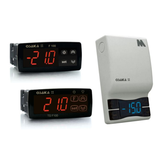
1.2 – DESCRIPTION OF FRONT PANEL
F 100 Front panel
it
is
TSF 100 Front panel
M1 Front panel
Advertisement
Table of Contents

Related Manuals for Osaka F 100


Summary of Contents for Osaka F 100
- Page 1 KEY LOCK FUNCTION INSTRUCTIONS FOR USE AND INSTALLATION MECHANICAL ASSEMBLY ELECTRICAL CONNECTIONS ELECTRICAL WIRING DIAGRAM OPERATION FUNCTION ON / OFF (STAND-BY) MEASURE AND DISPLAY - F 100 / TSF 100 / M1 - Manual de Usuario – V2.1 - PAG. 1 OSAKA...
- Page 2 The instrument has a parameter protection function with is locked. configurable password code in the "t, PP" parameter. - F 100 / TSF 100 / M1 - Manual de Usuario – V2.1 - PAG. 2 OSAKA...
- Page 3 Once reset visualize "---" Of display Menu at max. and min. the device will automatically exit in 15 seconds. - F 100 / TSF 100 / M1 - Manual de Usuario – V2.1 - PAG. 3 OSAKA...
- Page 4 = 3 - The buzzer is activated only to point out the keystrokes and O u t o ff o ff o ff alarm signals. P .P 2 P .P 2 P .P 2 - F 100 / TSF 100 / M1 - Manual de Usuario – V2.1 - PAG. 4 OSAKA...
- Page 5 An advantage and recommendation is the use of the supplied power supply KEY without connecting the F 100 / TSF 100 / M1 to power. - F 100 / TSF 100 / M1 - Manual de Usuario – V2.1 - PAG. 5 OSAKA...
- Page 6 Replace the device or 17 P.P2 Disabling postarrest oF/ 0.01 ÷ 9.59 memory send it to any repair output (relay) (min.sec ) ÷ 99.5 (min.sec.x10) - F 100 / TSF 100 / M1 - Manual de Usuario – V2.1 - PAG. 6 OSAKA...
- Page 7 - F 100/100 TSF: lateral Staples Temperature regulation: ON / OFF - M1: Area through screw Defrost control: interval for compressor failure. - F 100 / TSF 100 / M1 - Manual de Usuario – V2.1 - PAG. 7 OSAKA...
Need help?
Do you have a question about the F 100 and is the answer not in the manual?
Questions and answers