Advertisement
Quick Links
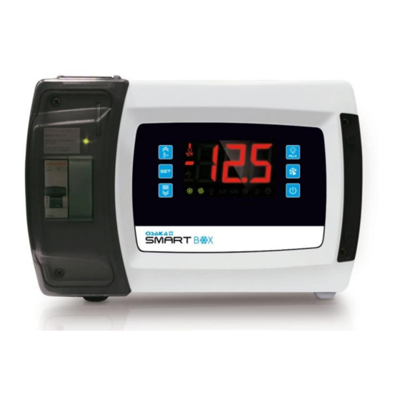
BOXED DIGITAL THERMOSTAT
FOR COLD ROOMS
Simple Manual – Version 1
www.osakasolutions.com
IMPORTANT
Read this document carefully before the installation and the
use of this device and respect all warnings; keep this
document alongside the device to solve further consults. Use
this device only as described in this document, and do not
use this device as a safety device.
To obtain further information, please consult the extensive
manual.
The device must be removed respecting the
local laws regarding the recollection of electronic
and electric devices.
1 – USER'S INTERFACE
1.1 Observations
Anytime you want to access the parameters or do an action,
make sure beforehand that the device is ON, that the
keyboard is not locked and that there isn't any other
procedure taking place.
1.2 Turn ON/OFF the device manually
1. Press the
key for 1 second.
1.3 The display
During the normal operation, the display will show the
selected temperature on the P5 parameter, except during a
defrosting, in which case the display will show the selected
temperature on the d6 parameter.
1.4 See other probes' temperature
1. Press the
key for 1 second: the display will show the
first variable that it's available to be read.
2. Press the
key or the
1.
"Pb1" room temperature or air input temperature
(according to the value of the P4 parameter)
2.
"Pb2" evaporator temperature
3.
"Pb3" auxiliary temperature
_
_
_
key to select:
– SMART BOX – Simple Manual – v1.1 – Page 1
OSAKA
4.
"Pb4" evaporation temperature
5.
"Pb5" low pressure
6.
"Pb6" CPT temperature ("Pb4" in SMART BOX,
SMART BOX M, SMART BOX MD, SMART BOX
SD, SMART BOX PLUS, SMART BOX PLUS M,
SMART BOX PLUS MD and SMART BOX PLUS
SD).
7.
"Pb7" auxiliary temperature 2
8.
"Pb8" auxiliary temperature 3
3. Press the
4. Press the
To exit the process:
5. Wait without pressing anything for 60 seconds or press the
key.
1.4 Activate / deactivate the "Turbo" mode
1. Make sure there is no ongoing defrosting, pre-dripping and
/ or evaporator's fan stoppage.
2. Press the
activation.
1.5 Activate the defrosting manually
1. Make sure that the "Turbo" mode is not running.
2. Press the
NOTE: If the evaporator's temperature is not below the d2
temperature, the defrosting won't be activated.
1.6 Turn ON/OFF the led manually
2. Press the
the status of the light.
_
1.7 Activate anti-fogging resistance
1.Press the
LED will turn on and the resistance will be activated.
Note: a configurable output must be configured as "anti-
fogging resistance".
1.8 Activate/deactivate the auxiliary output manually
1. Press the
LED will turn on.
NOTE: a configurable input must be configured as "auxiliary
output"
1.9 Some values related to the electronic expansion
valve (only available in SMART BOX VEX)
1. Press the
first variable that it's available to be read.
2. Press the
"SH" (instantaneous superheating)
"POS" (valve's opening required percentage)
_
"POr"
percentage).
3. Press the
4. Press the
To exit the process:
5. Wait without pressing anything for 60 seconds or press the
key.
1.10 Lock/Unlock the Keyboard
_
1. Press the
"Loc"/"UnL" whether it has been locked or unlocked.
1.11 Mute the warning buzzer
1. Press any key.
key to see the selected temperature.
key again to go back to the list.
key: the
LED will flash, indicating its
key for 4 seconds.
key: THE
LED will turn OFF/ON showing
key for 1 second: the "AUX1" or "AUX2"
key for 1 second: the "AUX1" or "AUX2"
key for 1 second: the display will show the
key or the
key to select:
(valve's
opening
key to see the data.
key again to go back to the list.
and
keys: The display will show
_
_
_
_
_
_
instantaneous
_
_
Advertisement

Subscribe to Our Youtube Channel
Related Manuals for Osaka Smart Box


Summary of Contents for Osaka Smart Box
- Page 1 1.11 Mute the warning buzzer “Pb1” room temperature or air input temperature 1. Press any key. (according to the value of the P4 parameter) “Pb2” evaporator temperature “Pb3” auxiliary temperature – SMART BOX – Simple Manual – v1.1 – Page 1 OSAKA...
- Page 2 1 second: the display will show the first variable that it’s available to be read. keys to select “rLS”. 2. Press the 3. Press the key. – SMART BOX – Simple Manual – v1.1 – Page 2 OSAKA...
- Page 3 To move from parameter to parameter: - Fixed: there is writing in progress; the SD 7. Press the keys. card cannot be removed. - Flashing: SD card not inserted/unrecognized – SMART BOX – Simple Manual – v1.1 – Page 3 OSAKA...
- Page 4 - Digital inputs: 100 m (328 ft). Resolution: 0.1 ºC (1 ºF). - Digital outputs: 100 m (328 ft). Protection: None. - RS-485 MODBUS port: 1.000 m (3.280 ft); – SMART BOX – Simple Manual – v1.1 – Page 4 OSAKA...
- Page 5 Additional features of the type 1 or type 2 action: C. Display: 3 digits display with decimal point and operation icons. Communication ports: 1 MODBUS RS-485 port (with MODBUS communication slave protocol). Signal and Alarm buzzer: incorporated. – SMART BOX – Simple Manual – v1.1 – Page 5 OSAKA...
-
Page 6: Parameter List
Enable the low pressure alarm (code “LP”; 1 = YES) - - - - Inferior limit in order activate the minimal low pressure alarm (code “LP”). (8) -0.5 Pt:10 (2) Minimal low pressure alarm delay (code “LP”). – SMART BOX – Simple Manual – v1.1 – Page 6 OSAKA... - Page 7 - - - - between two compressors. Type of compressor’s; 0 = timed, see also u3; 1 = by digital input, see also u3; - - - - 2 = by low pressure (only available in model SMART BOX VEX). PARAM. MIN. MAX.
- Page 8 - - - - protection, "C1t" will be shown; 8 = Compressor’s 2 thermal protection, "C2t" will be shown; 9 = Locked man alarm, “MiC” will be shown. – SMART BOX – Simple Manual – v1.1 – Page 8 OSAKA...
- Page 9 Management of the K4 digital output (only available in SMART BOX, SMART BOX M, SMART BOX MD and SMART BOX SD); 0 = ambient light; 1 = anti-fogging resistances; 2 = auxiliary output; 3 = alarm; 4 = - - - - door resistances;...
- Page 10 (16) This parameter only has a function if one of the outputs is configured as a resistance for a dead-zone operation. In such a case, u7 establishes at how many degrees below the working set point will the heat resistance be activated. – SMART BOX – Simple Manual – v1.1 – Page 10 OSAKA...
- Page 11 – SMART BOX – Simple Manual – v1.1 – Page 11 OSAKA...
- Page 12 13 – ELECTRICAL DIAGRAM_______________________________________________________________________ _____ – SMART BOX – Simple Manual – v1.1 – Page 12 OSAKA...
- Page 13 – SMART BOX – Simple Manual – v1.1 – Page 13 OSAKA...
- Page 14 – SMART BOX – Simple Manual – v1.1 – Page 14 OSAKA...
- Page 15 Connection for the models with data logging in compliance with the EN 12830 norm. – SMART BOX – Simple Manual – v1.1 – Page 15 OSAKA...
-
Page 16: Warranty And Repair
14 – WARRANTY AND REPAIR The controller has a repairing or replacement warranty due to manufacturing defects of 12 months from the purchasing date. OSAKA SOLUTIONS will automatically cancel aforementioned warranty and will not be held accountable for possible damages that result from: - The use, installation, usage or improper handling that differs from the one previously stated, and specially if it differs from the safety prescriptions established by the law.
Need help?
Do you have a question about the Smart Box and is the answer not in the manual?
Questions and answers