Table of Contents
Advertisement
USER'S MANUAL FOR COOL/HEAT
DIGITAL THERMOSTAT WITH
DEFROSTING
User's Manual – v1
www.osakasolutions.com
INTRODUCTION
in this manual there is the necessary
information for the proper installation and
usage instruction and maintenance of the
product, it is recommended to read it carefully
and to keep it.
In order to avoid dangerous or hazardous
circumstances for people, things or animals due to an
irregular operation or the malfunctioning of the thermostat, we
remind you that the installation must comply with and be
aware of the annexed safety systems, necessary to guarantee
the aforementioned safety.
Neither OSAKA SOLUTIONS nor its legal representatives are
responsible neither for the inadequate use of the
THERMOSTAT nor for the use of it not conforming to the
characteristics of the THERMOSTAT.
INDEX
1
DESCRIPTION OF THE CONTROLLER
1.1
GENERAL DESCRIPTION
1.2
FRONT PANEL DESCRIPTION
2
PROGRAMMING
2.1
QUICK SELECTION OF THE SET POINT
2.2
STANDARD PROGRAMMING OF THE PARAMETERS
2.3
PARAMETERS PROTECTION THROUGH PASSWORD
2.4
CUSTOMIZING PARAMETERS WITH / WITHOUT
PASSWORD
2.5
RESTORATION OF INITIAL PARAMETERS
2.6
KEYBOARD LOCKING FUNCTION
3
USAGE AND INSTALLATION WARNINGS
3.1
USAGE WARNING
3.2
MECHANICAL ASSEMBLING
3.3
ELECTRICAL CONNECTION
3.4
ELECTRICAL WIRING DIAGRAM
4
OPERATION
4.1
ON / OFF (STAND-BY) FUNCTION
"NORMAL" AND "ECONOMIC" MODE OF OPERATION
4.2
4.3
INPUTS AND DISPLAY CONFIGURATION
4.4
DIGITAL INPUT CONFIGURATION
4.5
4.6
4.7
4.7.1
4.7.2
4.7.3
4.7.4
4.7.5
4.7.6
4.8
4.8.1
4.8.2
4.8.3
4.9
4.10
5
6
6.1
6.2
6.3
7
7.1
7.2
7.3
7.4
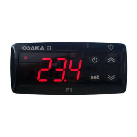
1 – DESCRIPTION OF THE CONTROLLER
1.1 – GENERAL DESCRIPTION
The F1 is an electronic digital thermostat with a microprocessor
adequate for applications of refrigeration and industrial processes,
equipped with temperature control with ON / OFF regulation and
defrosting control by compressor shutdown by time intervals.
The controller has one relay output and two NTC (10k) temperature
probe inputs, of which the second input can be used as a digital
input instead of as a probe input.
1.2 – FRONTAL PANEL DESCRIPTION
1 - "SET" KEY: By pressing and releasing quickly you can change
the Set Point.
By pressing for 5 seconds you can access the parameters
programming function. This function is used to edit the parameters
and to confirm the desired value.
It can be used alongside the "UP" key to modify the programming
level of the parameters.
Having the keyboard locked, if you press "SET" + "UP" during 5
seconds the keyboard will be unlocked automatically.
2 – "DOWN" Key:
You can lower the value of the SET POINT by pressing it directly
without having entered the menu. In the parameters menu you can
search the desired parameter and after pressing the selection of
the parameter with "SET" you lower or select the new value of the
parameter.
– F 1 – User's Manual – v1 – PAG. 1
OSAKA
TEMPERATURE REGULATION
COMPRESSOR PROTECTION AND STARTING DELAY
AUTOMATIC DEFROSTING CONTROL
DEFROSTING BY TIME INTERVALS
DEFROSTING BY THE TEMPERATURE OF THE
EVAPORATOR
DEFROSTING BY CONTINUAL TIME
OF THE COMPRESSOR'S OPERATION
MANUAL DEFROSTING
INTERVALS AND DURATION OF THE DEFROSTING
WITH EVAPORATOR PROBE ERROR
LOCKING OF THE DISPLAY DURING THE
DEFROSTING
ALARM FUNCTIONS
TEMPERATURE ALARMS
EXTERNAL ALARM OF DIGITAL INPUT
OPEN DOOR ALARM
OPERATING KEY "
" AND "DOWN / AUX"
PARAMETERS CONFIGURATION WITH KEY USB
PARAMETERS LISTING
PROBLEMS, MAINTENANCE AND WARRANTY
SIGNALING
CLEANING
WARRANTY AND REPAIRING
TECHNICAL DATA
ELECTRICAL FEATURES
MECHANICAL FEATURES
MECHANICAL DIMENSIONS, HOLES AND MOUNTING
FUNCTIONAL FEATURES
Panel frontal F 1
Advertisement
Table of Contents

Related Manuals for Osaka F1


Summary of Contents for Osaka F1
- Page 1 1 – DESCRIPTION OF THE CONTROLLER User’s Manual – v1 1.1 – GENERAL DESCRIPTION The F1 is an electronic digital thermostat with a microprocessor www.osakasolutions.com adequate for applications of refrigeration and industrial processes, equipped with temperature control with ON / OFF regulation and INTRODUCTION defrosting control by compressor shutdown by time intervals.
-
Page 2: Programming
“t.PP” parameter. To modify it the “UP” and “DOWN key must be pressed as well as “SP” to change the Set Point. – F 1 – User’s Manual – v1 – PAG. 2 OSAKA... -
Page 3: Electrical Connection
(blocked). To unlock the keyboard press “SET+UP” for 5 seconds and the display will show “LF” and all the keyboards functions will be operational again. – F 1 – User’s Manual – v1 – PAG. 3 OSAKA... -
Page 4: Electrical Wiring Diagram
(USA) [C0=ºC / 1º (no decimal); C1=ºC / 0.1º (with decimal); F0= ºF was a power failure, when the power comes back the system will / 1º; F1= ºF / 0.1º], always be as it was right before the interruption. -
Page 5: Temperature Regulation
Such function expects to activate up to 3 types of timing that you to make defrosting at the start of the controller, configure “d.Sd” = can choose according to the appropriate system regulation. “d.di” – F 1 – User’s Manual – v1 – PAG. 5 OSAKA... -
Page 6: Intervals And Duration Of The Defrosting
“A.PA” – Delay time when receiving power supply and turning the regulation controller on if it is in an alarm situation. “A.dA”- Delay time after a defrosting. “A.At” – Acting delay time of the temperature alarm. – F 1 – User’s Manual – v1 – PAG. 6 OSAKA... -
Page 7: Open Door Alarm
The KEY USB has a USB connection input, which allows connecting it to a PC, with which through the T e m p . Universal Conf or Osaka Set Up configuration software it is possible to configure the operation parameters. A . H A A . - Page 8 35 P.P3 output connections. 99.5 Delay of the oF ÷ 0.01 ÷ compressor’s start 9.59 (min.sec) 36 P.od when it gives voltage ÷ 99.5 to the controller. (min.sec) – F 1 – User’s Manual – v1 – PAG. 8 OSAKA...
-
Page 9: Signaling
2 = SPE 3 = SP and SPE 4 = Active SP 5, 6 = DO NOT USE Password to access 49 t.PP the operational oF ÷ 999 parameters. – F 1 – User’s Manual – v1 – PAG. 9 OSAKA... -
Page 10: Cleaning
Request a repairing B R A C K E T S document “RMA” (by email or fax) and fill it. It is necessary to send the RMA and the controller to the SAT OSAKA with prepaid shipping. 7 – TECHNICAL DATA 7.1 –... - Page 11 – F 1 – User’s Manual – v1 – PAG. 11 OSAKA...
Need help?
Do you have a question about the F1 and is the answer not in the manual?
Questions and answers