Table of Contents
Advertisement
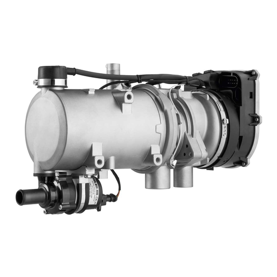
Coolant Heater
Thermo Pro 90 D (Diesel)
12 / 24 Volt
Installation Manual
– Improper installation or repair of Webasto heating and cooling systems can cause fire
or the leakage of deadly carbon monoxide leading to serious injury or death.
– To install and repair Webasto heating and cooling systems you need to have
completed a Webasto training course and have the appropriate technical
documentation, special tools and special equipment. Only genuine Webasto parts
may be used. See also Webasto air and water heaters accessories catalogue.
– Never try to install or repair Webasto heating or cooling systems if you have not
completed a Webasto training course, you do not have the necessary technical skills
and you do not have the technical documentation, tools and equipment available to
ensure that you can complete the installation and repair work properly.
– ALWAYS carefully follow Webasto installation and repair instructions and heed all
WARNINGS.
– Webasto heating and cooling systems require qualified and/or professional
installation and repair technicians. Warranty shall be void if not installed by a
certified or trained installer/repair technician who has successfully completed the
factory training course for installation and repair of Webasto heating and cooling
systems, and has been provided with the technical information, tools and equipment
required to properly complete the necessary installation /repairs.
– Product produces temperatures high enough to ignite surrounding combustible
materials such as inflammable liquids, gases, vapor, and other combustible matter.
The heater must be switched off when loading or unloading inflammable materials
to prevent the risk of explosion.
Advertisement
Table of Contents

Subscribe to Our Youtube Channel
Related Manuals for Webasto Thermo Pro 90 D


Summary of Contents for Webasto Thermo Pro 90 D
-
Page 1: Installation Manual
See also Webasto air and water heaters accessories catalogue. – Never try to install or repair Webasto heating or cooling systems if you have not completed a Webasto training course, you do not have the necessary technical skills and you do not have the technical documentation, tools and equipment available to ensure that you can complete the installation and repair work properly. -
Page 2: Table Of Contents
14.1 General Information ............... . 37 www.webasto.us Webasto Thermo & Comfort N.A., Inc. - Page 3 15.3 Thermo Pro 90 Dimensions ..............40 www.webasto.us Webasto Thermo & Comfort N.A., Inc.
-
Page 4: Safety And General Information
1.2 General Information Webasto Product North America, Inc. is pleased to provide this installation manual with the Thermo Pro 90 Heater. When used according to the guidelines stated in this manual, you can expect to provide years of trouble-free, enjoyable operation for your customer. -
Page 5: Regulation For Installation In The Vehicle
2.2.6 A clearly visible indicator within the user's field exclude all risk of injury or damage caused by of vision must show when the heater is switched direct contact. on or off. Webasto Thermo & Comfort N.A., Inc. www.techwebasto.com... - Page 6 Failure to follow the installation instructions and the notes contained therein will lead to all liability being refused by Webasto. The same applies if repairs are carried out incorrectly or with the use of parts other than genuine Webasto service parts. This will result in...
-
Page 7: Purpose / Version
Thermo Pro 90 3. Purpose / Version 3.1 Purpose of the Coolant Heater The Webasto Thermo Pro 90 coolant heaters are used in connection with the vehicle’s own heating system – to heat the cab, – to defrost vehicle windows and –... -
Page 8: Installation
The heater must be secured with at least three M8 represents sufficient screening. Please contact the screws. The screws must be tightened with a torque of Webasto technical support team in the event that radio 18 Nm. (13.3 lb-ft). interference occurs nevertheless. -
Page 9: Installation Location Examples
Installation Location Examples Thermo Pro 90 5. Installation Location Examples Figure 1: Installation locations Webasto Thermo & Comfort N.A., Inc. www.techwebasto.com... -
Page 10: Mounting The Heater To The Vehicle
B - Width 140mm (5.5”) L - Length 355mm (14”) L* - Length from control unit to inlet connection piece of circulation pump 381mm (15”) Figure 4: Thermo Pro 90 heater Inlets / Outlets / Dimensions www.webasto.us Webasto Thermo & Comfort N.A., Inc. - Page 11 Figure 5: Drill frame within the shaded area only! 310mm (12-13/64”) 80mm (3-5/32”) 70mm (2-3/4”) 150mm (5-29/32”) 23mm (29/32”) 50mm (1 31/32”) Figure 6: Mounting heater enclosure via back wall (Vertical or horizontal mounting) Webasto Thermo & Comfort N.A., Inc. www.techwebasto.com...
- Page 12 Thermo Pro 90 Mounting the Heater to the Vehicle 150mm 150mm 484mm 363mm 158mm 500mm Figure 7: Optional perpendicular mounting with bracket kit P/N 905838 www.webasto.us Webasto Thermo & Comfort N.A., Inc.
-
Page 13: Connection To The Vehicle Cooling System
Separate the heater supply and return connections at the engine as far apart as Optimum Cross-Flow Through Engine is practical for optimum engine heating and heater performance. See Figure 8. Figure 8: Ensure optimum cross-flow Webasto Thermo & Comfort N.A., Inc. www.techwebasto.com... -
Page 14: Various Plumbing Configurations
2. Vehicle heat exchangers 3. Coolant pump 4. Thermo Pro 90 heater 5. Coolant return connection 6. Engine coolant pump 7. Thermostat Figure 10: System configured in a “series” fashion with both heat exchangers. www.webasto.us Webasto Thermo & Comfort N.A., Inc. - Page 15 Figure 13: System configured with a bypass circuit within the rear heat exchanger circuit where an automated flow control valve is installed. Bypass is required in the event the valve is closed during heater operation. Webasto Thermo & Comfort N.A., Inc. www.techwebasto.com...
- Page 16 8. Automated control valve 9. Wye connectors 10. N/A 11. Auxiliary heat exchanger Figure 14: System configured with an additional auxiliary heat exchanger connected in “series / parallel” with rear heat exchanger circuit. www.webasto.us Webasto Thermo & Comfort N.A., Inc.
-
Page 17: Fuel Supply
Figure 15: Fuel system components 0 ° A. Fuel standpipe E. Fuel pump B. Connector hose F. Fuel line C. Fuel filter G. 90° Connector hose D. Hose clamp Webasto Thermo & Comfort N.A., Inc. www.techwebasto.com... -
Page 18: Fuel Standpipe Installation
B. Compression fitting C. Hex nut D. Metal washer E. Rubber washer F. Tank boss 1/4” NPT Figure 18: Standpipe installation - illustration 1 G. 25mm (1”) hole Figure 17: Webasto fuel standpipe www.webasto.us Webasto Thermo & Comfort N.A., Inc. -
Page 19: Fuel Tank
(item A in Figure 21). Do not over- tighten causing rubber washer to squeeze out! Figure 19: Standpipe installation - illustration 2 Fuel Tank Figure 21: Standpipe installation - illustration 3 Webasto Thermo & Comfort N.A., Inc. www.techwebasto.com... -
Page 20: Fuel Lines
The metering pump and fuel lines must not be installed within range of the radiated heat from hot vehicle parts. A heat shield must be used if necessary. Figure 22: Fuel line / coupler hose connection www.webasto.us Webasto Thermo & Comfort N.A., Inc. -
Page 21: Fuel Filter
8.5 Fuel Filter Only a Webasto filter is allowed to be used if the fuel is expected to be contaminated. Install vertically if possible, however at least horizontally (check flow direction). -
Page 22: Combustion Air Supply
The size of the ventilation opening must be increased accordingly if the temperature in the box exceeds the permitted ambient temperature of the heater (see Technical data). www.webasto.us Webasto Thermo & Comfort N.A., Inc. -
Page 23: Exhaust System
C. “L” bracket The exhaust muffler is secured to the heater using a coupler between the heater and muffler and a bracket fastened to the underside of the enclosure. See Figure 26 for details. Webasto Thermo & Comfort N.A., Inc. www.techwebasto.com... - Page 24 If the exhaust tube cannot be installed so that it slopes downwards at all points, a condensation drain hole with a diameter of 4 mm (5/32”) is to be made at its lowest point to allow condensate to drain. www.webasto.us Webasto Thermo & Comfort N.A., Inc.
-
Page 25: Electrical Connections
For sleeper and engine heating applications, Webasto recommends a four battery system for best results. A weather sealed fuse holder is to be fitted to protect the heater (supplied with the power / control harness). -
Page 26: Connecting The Controls
Thermo Pro 90 Electrical Connections 11.2 Connecting the Controls The heater can be switched on and off using the following Webasto controls: • Switch, see circuit diagrams in Figures 29 and 33. • Timer, see circuit diagrams in Figures 30 and 34. - Page 27 – Ensure good readability when selecting installation location. – Observe information on adhesive labels and colored markings when connecting the control element to vehicles wiring harness. Figure 32. SmarTemp drilling dimensions Webasto Thermo & Comfort N.A., Inc. www.techwebasto.com...
-
Page 28: Vehicle Fan
Engine “ON” 65°C (149°F) 75°C (167°F) 60°C (140°F) Engine “OFF” 80°C (176°F) 90°C (194°F) 75°C (167°F) If the terminal D+ signal is not applied, the temperatures are the same as those at “Engine off”. www.webasto.us Webasto Thermo & Comfort N.A., Inc. -
Page 29: Circuit Diagrams
Circuit Diagrams Thermo Pro 90 12. Circuit Diagrams Cable Cross Sections Cable Colors Legend Webasto Thermo & Comfort N.A., Inc. www.techwebasto.com... -
Page 30: Thermo Pro 90 Circuit Diagram Legend
To item M2 (Circulating pump) Plug connector, 9-pin To item X14 Plug connector, 9-pin To item S1 or P1 Plug connector, 4-pin To item X16 Plug connector, 4-pin To item P1 Metering pump Fuel pump for heater www.webasto.us Webasto Thermo & Comfort N.A., Inc. -
Page 31: Thermo Pro 90 With On/Off Switch
Circuit Diagrams Thermo Pro 90 Figure 33: Thermo Pro 90 with ON/OFF Switch - Connection Diagram Webasto Thermo & Comfort N.A., Inc. www.techwebasto.com... -
Page 32: Thermo Pro 90 With 7-Day Smartemp Control Fx Timer
Thermo Pro 90 Circuit Diagrams Figure 34: Thermo Pro 90 with 7-day SmarTemp Control fx Timer - Connection Diagram www.webasto.us Webasto Thermo & Comfort N.A., Inc. -
Page 33: Initial Start-Up
Has a pressure test been performed on the coolant system under all operating conditions? Have the coolant hoses been installed so that they are below the coolant filler cap? Has the coolant flow direction been verified? Webasto Thermo & Comfort N.A., Inc. www.techwebasto.com... - Page 34 Verify the correct fuses are in the specified locations per the installation manual. Ensure heater and vehicle fuse boxes are closed and secure. Was the Webasto fuse block installed in a location protected from water and / or moisture? Ω) Ensure blower motor resistor (1.0...
- Page 35 HEATER MUST BE SWITCHED “OFF” WHEN REFUELING AT FILLING STATIONS AND/OR WHILE LOADING OR UNLOADING FLAMMABLE MATERIALS FOR DANGER TRANSPORT, TO PREVENT THE RISK OF EXPLOSION. PLEASE REVIEW OWNER’S MANUAL FOR SAFETY AND USE INSTRUCTIONS. Webasto Thermo & Comfort N.A., Inc. www.techwebasto.com...
-
Page 36: Troubleshooting
If the system is operated with a switch, the nature of the fault is indicated by a flashing code on an indicator light (toggle of switch) during the run-on time of the heater. After five short signals, count the long flashes: No start (after 2 attempts to start) Flame failure Under-voltage or over-voltage www.webasto.us Webasto Thermo & Comfort N.A., Inc. - Page 37 F 13 Output vehicle fan short circuit F 14 Overheating protection defective F 15 Reference resistance not reached during start F 16 Exhaust gas temperature too high F 17 Exhaust temperature sensor defective Webasto Thermo & Comfort N.A., Inc. www.techwebasto.com...
-
Page 38: Technical Data
U4840 Coolant Pump Volume Flow @ 0.3bar (4.35 PSI) 700 l/h (3.08 gal/min) Dimensions 134 x 53 x 90 (5.28” x 2.08” x 3.5”) Weight .36 kg (.8 lbs) Table 1: Technical Data www.webasto.us Webasto Thermo & Comfort N.A., Inc. -
Page 39: Thermo Pro 90 Dimensions
Combustion air intake Exhaust outlet Fuel inlet pipe Coolant inlet Coolant outlet 355mm (14”) L* 381mm (15”) 232mm (9.13”) 140mm (5.5”) Figure 35: Dimensions of the Thermo Pro 90 Heater / Enclosure Box www.webasto.us Webasto Thermo & Comfort N.A., Inc. - Page 40 Thermo Pro 90 Technical Data NOTES www.webasto.us Webasto Thermo & Comfort N.A., Inc.
- Page 41 Technical Data Thermo Pro 90 Webasto Thermo & Comfort N.A., Inc. www.techwebasto.com...
- Page 42 Thermo Pro 90 Technical Data www.webasto.us Webasto Thermo & Comfort N.A., Inc.
- Page 43 Technical Data Thermo Pro 90 Webasto Thermo & Comfort N.A., Inc. www.techwebasto.com...
- Page 44 Webasto Thermo & Comfort N.A., Inc. 15083 North Road Fenton, MI 48430 Technical Assistance Hotline USA: (800) 860-7866 Canada: (800) 667-8900 www.techwebasto.com Org. 5/2014 Rev. 9/2015 P/N 5010926B...
Need help?
Do you have a question about the Thermo Pro 90 D and is the answer not in the manual?
Questions and answers