Table of Contents
Advertisement
Advertisement
Table of Contents

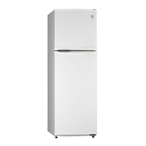
Summary of Contents for Daewoo FR-291
- Page 1 Refrigerator FR-291 JUL. 2006 Downloaded from Fridge-Manual.com Manuals...
-
Page 2: Major Accessories
FREEZER POCKET REF. SHELF COVER VEGETB CASE VEGETABLE CASE EGG CASE REFRIGERATOR ROOM EGG POCKET UTILITY POCKET JUMBO POCKET BOTTLE POCKET 2. QUALITY SPECIFICATION CONTENTS FR-291 CLASIFICATION FREEZER GROSS REFRIGERATOR 173L TOTAL 246L CAPACITY (L) FREEZER STORAGE REFRIGERATOR 159L TOTAL... - Page 3 2. NAME OF FARTS Downloaded from Fridge-Manual.com Manuals...
-
Page 4: Air Flow Diagram
3. AIR FLOW DIAGRAM Downloaded from Fridge-Manual.com Manuals... -
Page 5: Refrigerant Cycle Diagram
4. REFRIGERANT CYCLE DIAGRAM Downloaded from Fridge-Manual.com Manuals... -
Page 6: Machine Room View And Part List
5. MACHINE ROOM VIEW AND PART LIST Downloaded from Fridge-Manual.com Manuals... -
Page 7: Wire Diagram
6. WIRE DIAGRAM & SOLID WIRE DIAGRAM 1) WIRE DIAGRAM Downloaded from Fridge-Manual.com Manuals... - Page 8 2) SOLID WIRE DIAGRAM Downloaded from Fridge-Manual.com Manuals...
-
Page 9: Main Components
7. MAIN COMPONENTS 1. COMPRESSOR FR – 291 MODEL YX58LHP5 STARTING TYPE RSCR VOLTAGE 230V / 50Hz MAIN COIL RESISTANCE 19.4Ω SUB COIL RESISTANCE 25.6Ω 2. RELAY FR – 291 MODEL 4TM129SHBYY-52 RESISTANCE 33Ω MAX. VOLTAGE 355V MAX. CURRENT OL CURRENT 3.5A 3. -
Page 10: Power Cord
5. POWER CORD FR – 291 TYPE 3x0.75 ㎟ LENGTH 1.80m 6. TEMPERATURE FUSE FR – 291 VOLTAGE 250V CURRENT ℃ WORKING TEMP. 7. Bi-METAL FR – 291 MODEL PST - 3 ± OFF TEMP. 7. DEFROST TIMER FR – 291 MOEDL CF-3001-21 CYCLE TIME... -
Page 11: Fan Motor
9. FAN MOTOR FR – 291 MODEL DAI-6122-DESFD TYPE SHADED POLE RATING 230V/50HZ INPUT 5.0W POLE 2 POLE 2000 ± 150 rpm 10. R-THERMOSTAT FR – 291 MODEL GNF-175D-01F(1) RATING AC 250V/60Hz ℃ ON/OFF TEMP. 2.5 ± 2.5 11. DOOR SWITCH FR –... - Page 12 Downloaded from Fridge-Manual.com Manuals...
- Page 13 PART CODE PART NAME Q’TY REAMRK 3010815700 CABINET URT AS 3011755200 DOOR S/W AS WDS001C-01 3012924600 HINGE *T AS 3016000301 SPECIAL BOLT M5 x L14 3001400000 COVER *T HI 3012924500 HINGE *M AS 3016004000 SPECIAL BOLT M6 x L10 3012924700 HINGE *U AS 7650602511 BOLT HEX...
- Page 14 3015511000 WINDOW R GPPS 3011187300 CASE ICING 3017843700 SHELF F GPPS 3017843600 SHELF R GPPS 3001400700 COVER VEGETB CASE GPPS 3011187600 CASE VEGETB GPPS 3019027900 POCKET F GPPS 3012319500 GASKET F DR AS PVC-S+MAGNET 3011766900 DOOR F URT AS 3011187200 CASE EGG 3019027800 POCKET EGG...
-
Page 15: Methods Of Exchanging Main Parts
9. Methods of exchanging main parts. 1. F LOUVER PART - Remove the screw cap, and unscrew the fixing screw(2EA). Pull the louver forward, grasping at the fan cover and upper corner of louver. - Disassemble fan motor harness and remove Louver As.. - Page 16 2. EVAPORATOR PART - Pull the suction pipe and capi. Tube forward, with care not to bend the pipes sharply. - Hold up evaporator and pull it forward. - Remove the evaporator pad. - To remove defrost heater, cut the clamp cable first, disassemble the harness then pull down the heater.
- Page 17 - To exchange the Bi-Metal, first cut the clamp cable then disassemble the harness. - Extract the Temp. Fuse in the evaporator then disassemble the harness . - The new Temp. Fuse should be located in the same position in the evaporator. 3.
- Page 18 - Unscrew the fixing screw(1EA) . - Pull down the control box, then disassemble the harness. - Remove the lamp cover with screwdriver etc. pushing the front hooker part of the cover then lift up the cover. - Unscrew the fixing screw of the lamp socket. Downloaded from Fridge-Manual.com Manuals...
- Page 19 - Pull the lamp forward, then disassemble the connector. - The assembling procedure of new lamp is the reverse of disassemble steps. 4. DOOR SWITCH PART - In removing the door switch, push the door switch left, insert a pointed rods as screw- driver in the right gap, and push the rod left and pull the door switch forward.


Need help?
Do you have a question about the FR-291 and is the answer not in the manual?
Questions and answers