Advertisement
Table of Contents
- 1 Parts Listing
- 2 Exploded View
- 3 Step 1- Unfold Frame
- 4 Step 2- Handlebar Assembly
- 5 Handlebar 2
- 6 Backrest Pad &
- 7 Foot Rest Plate
- 8 STEP 5 -Final Assembly
- 9 Height Adjustment Knob
- 10 Head Pad
- 11 For any Parts Required, DO NOT CALL TECHNICAL SUPPORT. Please Visit Our Web Site: Www.extremeproductsgroup.com
- 12 Usage Guidelines
- Download this manual
S
Deluxe Heat & Massage Inversion Table
Model ITM 4500
Ver 080615
CAUTION:
WARNING: DO NOT USE THIS
INVERSION TABLE WITHOUT A
PHYSICIAN'S APPROVAL
It is recommended that Inverting
upside down be supervised.
Keep children away.
Read all instructions carefully
before using.
Tighten all bolts before using
equipment.
Leave adequate space to
properly invert.
Questions/ Comments
PLEASE DO NOT CONTACT THE
STORE FOR PARTS OR
SERVICE QUESTIONS
Extreme Products Group is committed to
providing the very best of quality and
customer satisfaction for all of the products
we distribute. If for any reason , you are
dissatisfied with the product you have
purchased or need assistance in any way,
please do not hesitate to contact our
technical support voicemail system
:623-888-6379
at:
and a service advisor
:
will return your call. Or send us an email at
service@extremeproductsgroup.com
For any and all parts, please visit:
Web: www.extremeproductsgroup.com
Mon.-Fri 9:00 am – 5:00 pm Phoenix Time
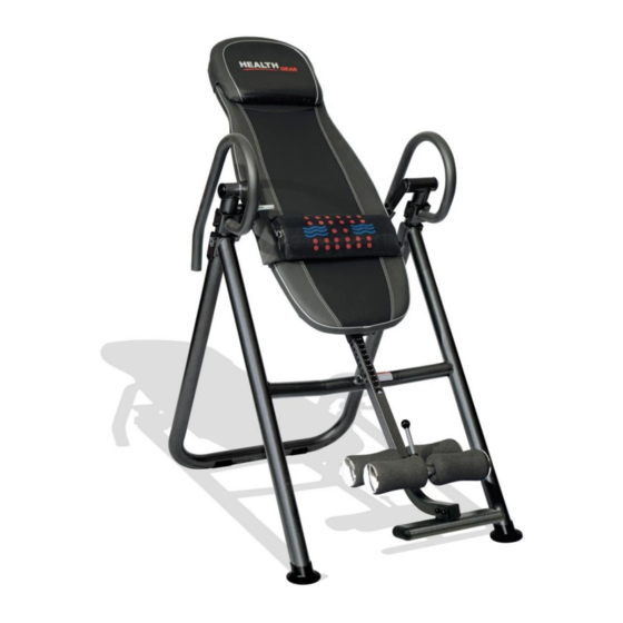
Photo may differ from actual product
1
Advertisement
Table of Contents

Related Manuals for Health GEAR ITM 4500


Summary of Contents for Health GEAR ITM 4500
- Page 1 Deluxe Heat & Massage Inversion Table Model ITM 4500 Ver 080615 CAUTION: WARNING: DO NOT USE THIS INVERSION TABLE WITHOUT A PHYSICIAN’S APPROVAL It is recommended that Inverting upside down be supervised. Keep children away. Read all instructions carefully before using.
- Page 2 BEFORE BEGINNING ASSEMBLY… Take a few moments to familiarize yourself with the specific parts and hardware included with your product. Make sure all the parts and hardware are included in the carton and examine them for any damage that may have occurred in transport. Some parts may be pre-assembled and pre-installed. CAUTION WARNING: BEFORE STARTING ANY INVERSION PROGRAM, CONSULT YOUR PHYSICIAN.
-
Page 3: Parts Listing
Parts Listing Part# Description Part# Description Base-frame-Front/Rear 1F/1R Hand Controller Handlebar Power Adaptor Base Frame End Caps Backrest Support Tube Back Rest Pad Arc Caps Body Height Adjustment Tube Connecting Bracket - Left Adjustable Leg Hold Tube Connecting Bracket - Right Leg Tube-REAR Wrench-#13/#17 Foot Rest Plate... -
Page 4: Exploded View
Exploded View 17 20 01 Rear 01 Front * For Any Parts Required, DO NOT CALL TECHNICAL SUPPORT. Please visit our web site: www.extremeproductsgroup.com * For Any Parts Required, DO NOT CALL TECHNICAL SUPPORT. Please visit our web site: www.extremeproductsgroup.com... -
Page 5: Step 1- Unfold Frame
Step 1- Unfold Frame Carefully remove Base Frame from carton, and unfold. Insert safety pin(26) into Right side of frame Note Front, Rear, Right and Left Sides for further assembly NOTE: Both Side Insert safety Rotational Brackets need pin(26) to point down toward floor for further assembly RIGHT 01 Rear... -
Page 6: Step 2- Handlebar Assembly
Step 2- Handlebar Assembly RIGHT LEFT STEP 2 Attach the Handlebar Right (02) to the Base frame Rear(01) using 2 Bolts (09), 2 Washers (10), and 2 Nuts (11). Repeat for Handlebar Left (02). TIGHTEN ALL BOLTS AT THIS TIME * For Any Parts Required, DO NOT CALL TECHNICAL SUPPORT. -
Page 7: Backrest Pad &
Step 3- Backrest Assembly to Base Frame Brackets must face down Note: Rotational Side Brackets must face DOWN toward floor Lift Entire Bed Assembly UP into Rotational Brackets And Secure with Bolts, Nuts, and Washers STEP 3 Connecting Backrest Pad & Assembly to Frame Attach the Completed Backrest Pad Assembly to the Base frame Unit using Bolts (13), Flat Washers (10) and Lock Nuts (11) as shown Note that side rotational brackets must face down and bed must be lifted... -
Page 8: Foot Rest Plate
STEP 4 -Body Height Adjustment Tube and Rollers A- Install Foot Rest B- Lift out front roller tube (06) from Height Plate (08) into Height Adjustment Selector Tube (05) and position as Adjustment Tube (05) shown. Slide Foam Rollers (22) over front Tube (06) using Hexagonal Bolts and insert Plastic End Caps (24) (14), &... -
Page 9: Step 5 -Final Assembly
STEP 5 -Final Assembly 17 20 Slide Completed Height Adjustment Tube and Foot Rest Assembly (05) into Backrest Support Tube (03) and lock into place using Height Adjustment Knob (17) and Safety Pin (20) This Height Adjustment Knob is spring loaded and should “lock”... -
Page 10: Head Pad
Heat / Massage Pad and Head Pad Assembly to Backrest Pad Step 6 Connecting Head Pad and Heat/Massage Lumbar Pad Attach the Heat / Massage Lumbar Pad(48)and the Head Pad(45) to Backrest Pad(47) in Desired Position using Velcro. Controller(46) can be stored in Right Side Pocket of Backrest Pad(44) for easy access. -
Page 11: For Any Parts Required, Do Not Call Technical Support. Please Visit Our Web Site: Www.extremeproductsgroup.com
PRECAUTIONS WARNING: 300 LB WEIGHT CAPACITY To reduce the risk of serious injury, read all important precautions instructions and warnings in this manual before using the Inversion System. Extreme Products Group assumes no responsibility for personal injury or property damage sustained by or through the use of the Inversion System. - Page 12 Controller Instruction Connect the product with power source by 12V adaptor and the indicator light of "POWER" will blink into standby. Press the "POWER" button to start the massage function, the power indicator light will Press "HEAT" button to stop blinking, the massage start the heat function.
-
Page 13: Usage Guidelines
USAGE GUIDELINES INVERSION SELECTOR PIN Familiarize yourself with the Inversion Selector Pin located on the Right Side of the Inversion Table. The positioning of the pin will determine the degree of Inversion that you are comfortable with. The 3 selections are: 20- Slight Inversion 40-Moderate Inversion 60- Enhanced Inversion... - Page 14 USAGE GUIDELINES- Securing Feet and Ankles Photos may be different than actual product Step 2- Slide Feet under Foam Rollers and rest heels against rear Heel Cups. Release top button and slowly “ratchet back” front rollers against legs. Step 3- Ratchet front rollers tight against legs and secure legs and ankles in place by making sure leg assembly...
- Page 15 USAGE GUIDELINES- How to Invert Photos may be different than actual product * For Any Parts Required, DO NOT CALL TECHNICAL SUPPORT. Please visit our web site: www.extremeproductsgroup.com...
- Page 16 Health Gear is a licensed Trademark and Distributed By: Extreme Products Group 6635 W. Happy Valley Rd Suite A-104, #213 Phoenix, AZ 85310 Technical Support Voicemail: 623-888-6379 Calls will be returned in the order they were received Fax: 623-434-9100 Email: service@extremeproductsgroup.com...
Need help?
Do you have a question about the ITM 4500 and is the answer not in the manual?
Questions and answers