Table of Contents
Advertisement
S
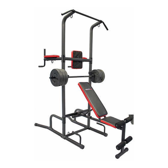
Functional Cross Training Tower System With Bench
Model CFT2.0
Version: 712017
CAUTION:
WARNING: CHECK WITH YOUR
PHYSICIAN BEFORE STARTING
ANY EXERCISE PROGRAM
Do Not Allow Children to Play on
or Around this Product.
Read all instructions carefully
before using.
Tighten all bolts before using
equipment.
Leave adequate space to
properly exercise
Questions/ Comments
PLEASE DO NOT CONTACT THE
STORE FOR PARTS OR
SERVICE QUESTIONS
Extreme Products Group is committed to
providing the very best of quality and
customer satisfaction for all of the products
we distribute. If for any reason , you are
dissatisfied with the product you have
purchased or need assistance in any way,
please do not hesitate to contact our
knowledgeable support staff as follows:
Phone:623-888-6379
Email: service@extremeproductsgroup.com
Web: www.extremeproductsgroup.com
Photo may differ from actual product
Mon.-Fri 9:00 am – 5:00 pm Phoenix Time
1
Advertisement
Table of Contents

Subscribe to Our Youtube Channel
Related Manuals for Health GEAR CFT2.0


Summary of Contents for Health GEAR CFT2.0
- Page 1 Functional Cross Training Tower System With Bench Model CFT2.0 Version: 712017 CAUTION: WARNING: CHECK WITH YOUR PHYSICIAN BEFORE STARTING ANY EXERCISE PROGRAM Do Not Allow Children to Play on or Around this Product. Read all instructions carefully before using. Tighten all bolts before using equipment.
- Page 2 BEFORE BEGINNING ASSEMBLY… Take a few moments to familiarize yourself with the specific parts and hardware included with your product. Make sure all the parts and hardware are included in the carton and examine them for any damage that may have occurred in transport. Some parts may be pre-assembled and pre-installed. CAUTION WARNING: BEFORE STARTING ANY EXERCISE PROGRAM, CONSULT YOUR PHYSICIAN.
-
Page 3: Parts Listing
Parts Listing DESCRIPTION Q'TY DESCRIPTION Q'TY ITEM ITEM SEAT FRAME RIGHT BASE FRAME FOAM ROD LEFT BASE FRAME BACKREST ADJUSTABLE VKR PAD SUPPORT VERTICAL STABILIZER SEAT INCLINE BAR SUPPORT PLATE DIP HANDLE BASE CONNECT FRAME SEAT CUSHION BENCH SUPPORT FOAM ROLL FRAME LOWER UPRIGHT FRAME BENCH LOCKING KNOB... - Page 4 Parts Identifiler...
-
Page 5: Hardware Identifier
Hardware Identifier... - Page 6 Hardware Identifier...
- Page 7 Hardware Identifier...
-
Page 8: Exploded View
Exploded View TO VIEW AN ASSEMBLY VIDEO OF THIS PRODUCT, PLEASE VISIT OUR WEB SITE AT: WWW.EXTREMEPRODUCTSGROUP.COM * For Any Parts Required, DO NOT CALL TECHNICAL SUPPORT. Please visit our web site: www.extremeproductsgroup.com * For Any Parts Required, DO NOT CALL TECHNICAL SUPPORT. Please visit our web site: www.extremeproductsgroup.com... -
Page 9: Step 1- Lower Frame Assembly
Step 1- Lower Frame Assembly Connect #1 Right Base Frame, #2 Left Base Frame and 2- #8 Lower Uprights With #6 Base Connect frame using 4-#39 M10X80 Bolts and 8 #43 M10 washers And 4- #45 M10 Locknuts as pictured in Diagram 1. Diagram 1 Hand Tighten Bolts * For Any Parts Required, DO NOT CALL TECHNICAL SUPPORT. - Page 10 Step 2- Support Braces & Middle Frame Assembly A. Insert 2-#10 upright Frames over Tapered end of #8 Lower Uprigh Frame and line up holes. B. Using 2-#38 M10X75 Bolts and 2 # 43 M10 washers connect #7 Bench support frame as pictured in Diagram 2 C.
- Page 11 Step 3- VKR & Upper Frame Assembly A. Insert #9 Top Upright Frame over tapered end of #10 Upright Frame And line up holes so curved portion of #9 Faces towards back of the Tower. B. Attach # 5 Dip Handle and # 3 VKR Pad Support to #9 Top Upright Frame Using 4-#37 M10X75, 4-# 43 M10 Washers and 4-# 44 Locknuts C.
- Page 12 Step 4- Bench Frame Assembly A. Attach #20 Bench Front Leg to #19 Bench Main Frame and #28 Support Plate Using 2-#38 M10X75 Bolts,2-#46 M10X20 Bolts,6-#43 M10 Washers and 2-#45 M10 Locknuts. B. Hook Bench Main Frame U Clamp over #7 Bench Support Frame and Secure with two # 31 Bench Locking Knob as Pictured in Diagram 4 Diagram 4 Hand Tighten Bench Bolts...
- Page 13 Step 5- Seat & Backrest Frame Assembly A. Attach two #24 Seat Frames and two #21 Backrest Frames to #19 Bench Main Frame using 1-# 42 M10X180 Bolt, 2-#43 M10 Washers and 1-# M10 Locknut as Pictured In Diagram 5. (Note Middle Holes on two # 24 should face inwards;Middle Holes on two # 21 should face inwards.) B.
- Page 14 Step 6- Bench Pads and Roller Assembly A. Attach #29 Seat Cushion to two #24 Seat Frames Using 4-#41 M8X38 Bolts and 4-# 44 M8 Washers. (Note make sure #27 is Still mounted between two #24) B. Attach #23 Long Backrest Cushion to two #21 Backrest Frames using 4-#41 M8X38 Bolts and 4 M8 Washers .
- Page 15 STEP 7- Arm Pads & Back Pad A. Attach # 13 Backrest Cushion to #3 VKR Pad Support using 2#40 M8X16 Bolts and 2-# 44 M8 Washers B. Attach #14 VKR Cushions to #5 Dip Handles using 4 M8X65 Bolts and 4-# M8 Washers as pictured in Diagram 7 C.
-
Page 16: Warnings And Precautions
WARNINGS & PRECAUTIONS WARNING: 300 LB WEIGHT CAPACITY To reduce the risk of serious injury, read all important precautions instructions and warnings in this manual before using this Power Tower. Extreme Products Group assumes no responsibility for personal injury or property damage sustained by or through the use of this Tower. - Page 17 Health Gear is a licensed Trademark and Distributed By: Extreme Products Group 6635 W. Happy Valley Rd Suite A-104, #213 Phoenix, AZ 85310 Technical Support: 623-888-6379 Fax: 623-434-9100 Email: service@extremeproductsgroup.com For All parts requests, please do not call our Technical service number but visit our web site at www.extremeproductsgroup.com...
Need help?
Do you have a question about the CFT2.0 and is the answer not in the manual?
Questions and answers
Hello, The adjustable seat hinge broke off so that the seat is no longer connected. Is it possible to get a replacement part.