Vapotherm precision flow Operating Instructions Manual
Hide thumbs
Also See for precision flow:
- Quick reference manual (2 pages) ,
- Instructions for use (2 pages) ,
- Instructions for use manual (32 pages)
Advertisement
Table of Contents
- 1 Table of Contents
- 2 Symbols
- 3 Indications, Warnings and Cautions
- 4 Overview
- 5 Controls, Displays & Connections
- 6 Modes of Operation
- 7 Initial Assembly
- 8 Setting up
- 9 Adjustments
- 10 Connecting to Patient
- 11 Changing the Disposable Patient Circuit
- 12 Alarms
- 13 Shut down
- 14 Cleaning and Disinfection
- 15 Specifications
- Download this manual
Advertisement
Table of Contents

Related Manuals for Vapotherm precision flow


Summary of Contents for Vapotherm precision flow
- Page 1 Precision Flow ® Operating Instruction Manual...
-
Page 2: Table Of Contents
Cleaning and disinfection Section 16 Specifications Appendix: Audio Tone Characteristics Software modes EMC Guidance Precision Flow ® Packaging contains: Precision Flow ® Unit Operating Instruction Manual Quick Reference Guide Power Cord O2 Sensor cell Air & Oxygen Inlet Particulate Traps with Connectors... -
Page 3: Symbols
Symbols Vapotherm Inc. has declared that this product conforms with the European Council Directive 93/42/EEC Medical Device Directive when it is used in accordance with the instructions provided in the Operation Manual. 0297 This symbol indicates that the waste of electrical and electronic equipment must not be disposed as an unsorted municipal waste and must be collected separately. -
Page 4: Indications, Warnings And Cautions
Service on the device should only be performed by qualified, certified service technicians. To prevent injury, do not attempt to do any service to the Precision Flow® while a patient is connected to the device. If the device is damaged or not working properly, do not use. Contact Vapotherm or your authorized Vapotherm representative. - Page 5 4 psi (28 kPa). However, for the full specified range of gas flows and oxygen percentages, both gas inlet pressures must be 40 psi (276 kPa) or above. Precision Flow has not been tested for use in Field transport. When used with approved ancillary equipment the Precision Flow may be used for transferring patients within the hosiptal.
-
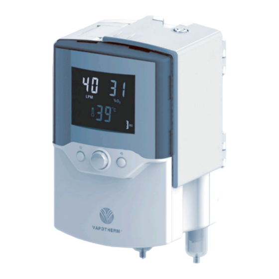
Page 6: Overview
Section 2 Overview The Precision Flow® is a system for high flow humidified respiratory therapy by nasal cannula. It incorporates the Vapotherm core humidification technology with an electronic blender and flow controller. The water and gas pathways are both incorporated into a removable, disposable patient circuit. - Page 7 Unlike most humidifiers, there is no direct contact between the water and gas streams. The gas stream leaves the cartridge saturated with vapor at the set temperature. Note: Use only approved cartridges from Vapotherm Inc. • Patient delivery tube.The warmed humidified gas passes through the center of a triple-lumen heated delivery tube.
-
Page 8: Controls, Displays & Connections
5. Gas supply fault 13. Blocked tube 6. Status LED 7. Run/Standby button (see note) ® Note:The Precision Flow has no ON/OFF switch. Plug the unit into a wall outlet to keep the battery fully charged Page 8 3001002 Rev. P... - Page 9 Section 4 Controls, displays & connections Front view 1. Folding carrying handle 2. Multi-function display: • Shows set values for oxygen %, flow and temperature • Icons indicate alarm conditions 3. Alarm mute: • Press to silence alarms for up to 2 minutes •...
- Page 10 Section 4 Controls, displays & connections Rear view 1. Hinged door • Open forward to install or remove disposable water path 2. Vent 3. Access panel for oxygen sensor (see note) 4. Pole clamp 5. Power cord connection and fuse holder 6.
-
Page 11: Modes Of Operation
Section 4 Controls, displays & connections WARNING: Heater plate may Docking station for disposable water path be hot! Arrows show location of optical sensor ports. Do not scratch or scrub the ports. Do not apply organic solvents or bleach. Section 5 Modes of operation Mode Action Indicator light color... -
Page 12: Initial Assembly
Section 6 Initial assembly ® Certain accessories must be installed in the Precision Flow unit before it can be used. These will normally be supplied in a separate package from the main unit as some are country- specific.The power cord plugs into the IEC60320-compliant receptacle on the rear panel. -
Page 13: Setting Up
5-wheel IV pole, with the base of the unit not more than 40” (102cm) above the floor. Fixed rail supports may also be used. Use with Vapotherm approved IV poles. 7-4. Connect oxygen and air supply hoses to correct inlets, then connect them to the wall outlets. - Page 14 Section 7 Setting up 7-5-2. Fit the delivery tube to the disposable water path as shown. Press firmly into place. Insert fully. Both latches must click shut. Tube clamp Water inlet tube Spike Assembled disposable patient circuit ready for insertion. Patient delivery tube Page 14...
- Page 15 Section 7 Setting up 7-6. Inserting disposable patient circuit: 7-6-1. Open hinged door to expose the docking station. 7-6-2. Hold disposable patient circuit by its handle, with the delivery tube downward as shown. 7-6-3. Slide disposable patient circuit downward into the docking station until it stops.
- Page 16 Section 7 Setting up WARNING: Use high–flow cartridge for flows 5-40 lpm and low-flow cartridge for flows 1-8 lpm. 7-7. Plug in power cord, and check that all the display indicators light. The Precision Flow ™ performs a self-test: • all icons and numeric displays light up for a few seconds •...
-
Page 17: Adjustments
(276 kPa) the full specified range of flows and oxygen mixtures is not available. The ® Precision Flow detects the actual inlet pressures and calculates the range of values that can be achieved. An alarm sounds if the operator attempts to make settings outside this range. -
Page 18: Connecting To Patient
Section 8 Adjustments • If oxygen is not connected, the blender setting will be fixed at 21%. If air is not connected the setting is fixed at 100%. An audio signal sounds if the operator attempts to set any other value. •... - Page 19 Section 9 Connecting to patient WARNINGS: • Always follow aseptic technique (including proper hand washing and avoiding direct hand contact with connection points) when setting up the Precision Flow and Standard ™ Precautions when placing on a patient. • Cannula should not obstruct the nares of the patient.
-
Page 20: Changing The Disposable Patient Circuit
11-1. Stop the unit by pressing the Run/Standby button. 11-2. Clamp the water inlet tube connected to the sterile water. 11-3. Open the door to expose the disposable water path. 11-4. Lift the disposable patient circuit out of the Precision Flow unit and discard in accordance ™... -
Page 21: Alarms
(fast triple beeps). • LOW PRIORITY alarms require attention as soon as reasonably possible and are indicated by infrequent intermittent tones (slow double beeps). In addition to the medium and low alarms, the Precision Flow emits the following audio ™... - Page 22 Section 12 Alarms Alarm Table Alarm icon Audio Signal Indicates Cause Action General fault Medium Malfunction of Internal compo- Cannot be corrected (flashing) Priority sensor or con- nent failure by user: disconnect Cannot be trol system patient. Shut off unit, muted send for service.
- Page 23 Section 12 Alarms Alarm Table Alarm icon Audio Indicates Cause Action Signal Cartridge fault Medium Cartridge and/ RUN mode: Disconnect patient. Remove Priority or DPC not faulty sensor disposable patient circuit. detected. Unit or cartridge Check cartrridge installation. will not run not detected.
-
Page 24: Shut Down
AC source. It is recommended that the unit is connected to AC for at least two hours once a month to maintain battery charge. Section 14 Routine maintenance Note: The internal backup battery should be replaced every two years. Contact Vapotherm for further information. 14.a Oxygen sensor The oxygen sensor (part no. -
Page 25: Cleaning And Disinfection
Do not expose the surface of the heater plate on the Precision Flow unit to concentrations of Chlorine solution (Sodium Hypochlorite) for a prolonged period of time, as this may cause surface damage to the metal plating. -
Page 26: Specifications
Section 16 Specifications PHYSICAL CHARACTERISTICS Dimensions: Height 11.5”(300mm), width 8”(200mm), depth 7”(180mm), excluding IV pole clamp and gas filters. Weight: 10.6 lb (4.81 kg) without disposable patient circuit Circulating Water Volume: 400 ml approx. including delivery tube and cartridge. Mounting: Rear mounted clamp fits IV poles up to 1.5”(38mm) diameter. - Page 27 Section 16 Specifications PERFORMANCE Flow rate: STANDARDS Designed to conform to the following standards: IEC 60601-1 UL60601-01 CSA C.22.2/No. 601.1 AS/NZS 3200.1.2 EN60601-1 ISO 8185 ISO 11195 ISTA-2A ENVIRONMENTAL Operating Ambient temperature: 18-30°C Ambient relative humidity: 0-90% RH non-condensing Ambient Pressure: Standard atmospheric – Not to be used in hyperbaric conditions Storage and Shipping Ambient temperature: -10 - +50°C Ambient relative humidity: 20-90% RH...
- Page 28 Appendix Standard Cannula Prong Outer Size Part No. Dia. (mm) Max. Flow Premature MN1100A Neonatal MN1100B Infant MI1300 Intermediate Infant MI1300B SOLO cannula SOLO1300 Pediatric Small MPS1500 Pediatric/Adult Small MP1500 Adult (base) MA1700 Audio Tone Characteristics Page 28 3001002 Rev. P...
- Page 29 The diagram illustrates the operating modes for the unit. • Immediately on connection to AC power a POST (Power-On Self Test) is run to verify proper function of subsystems, sensors and actuators in the Precision Flow ® • On successfully completing the POST the unit enters STANDBY unless there is a test failure, when the system alarms, enters FAULT mode and can not be started.
- Page 30 Guidance and manufacturer’s declaration - electromagnetic emissions The Precision Flow™ is intended for use in the electromagnetic environment specified below. The customer or the user of the Precision Flow™ should assure that it is used in such an environment. Emissions test...
- Page 31 The sole remedy for this warranty is that Vapotherm shall repair or, at its option, replace any part or all of any Product that is defective at no cost to the Customer. Vapotherm shall pay any shipping charges required in repairing or replacing any part or all of a Product provided that such Product is shipped within three (3) months of the date of purchase by the Customer.
- Page 32 Vapotherm Inc. 22 Industrial Drive Exeter, NH 03833 Phone: 603-658-0011 Fax: 603-658-0181 3001002 Rev. P Page 32 3001002 Rev. P...
Need help?
Do you have a question about the precision flow and is the answer not in the manual?
Questions and answers