Advertisement

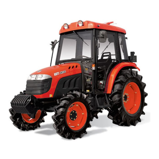
Congratulations,and welcome to the fabulous world of KIOTI DK451/501/551 ownership,where serious work is
made fun again!
This versatile tractor is a culmination of the entire tractor and diesel knowledge gained by the DAEDONG
INDUSTRIAL CO.,LTD over the years since 1947 and has been designed with the finest materials and under
rigid quality control standards set forth by the DAEDONG ENGINEERING DEPARTMENT.
Knowledge of tractor operation is essential for many years of dependable service and reliability.to help new
owners familiarize themselves with the KIOTI DK451/501/551, it is the policy of KIOTI tractor to provide an
owners manual which includes helpful information about tractor safety,operation and maintenance. If the infor-
mation you seek is not found in this manual, your KIOTI tractor dealer will be happy to help you.please feel free
to contact DAEDONG INDUSTRIAL CO.,LTD with your questions/concerns. Throughout this manual you will
see text in bold type, preceded by the worlds DANGER, WARNING, CAUTION or IMPORTANT.
Such text has the following significance.
Signs
DANGER
WARNING
CAUTION
IMPORTANT
FOREWORD
This mark indicates hazardous situation which, if not observed, may result in death or
fatal injury.
This mark should be indicated for most dangerous situations only.
This mark indicates potentially hazardous situation which, if not observed, may result in
death or moderate injury.
This mark indicates potentially hazardous situation which, if not observed, may result in
minor or moderate injury. And this mark can be used as a warning against unsafe activities.
This mark indicates emphasis on notable characteristics in working procedures or infor-
mation on working procedures and technology for convenient use.
Description

Advertisement

Table of Contents
loading

Summary of Contents for Kioti DK451

  • Page 1 If the infor- mation you seek is not found in this manual, your KIOTI tractor dealer will be happy to help you.please feel free to contact DAEDONG INDUSTRIAL CO.,LTD with your questions/concerns. Throughout this manual you will see text in bold type, preceded by the worlds DANGER, WARNING, CAUTION or IMPORTANT.
  • Page 2 ABBREVIATION LIST Abbreviations Definitions Four Wheel Drive American Petroleum Institute ASAE American Society of Agricultural Engineers, USA ASTM American Society of Testing and Materials, USA Feet Per Minute Hi-Lo High Speed-Low Speed Hydrostatic Transmission Meters Per Second P.T.O Power Take Off RH/LH Right-hand and Left-hand sides are determined by facing in the direction of forward travel...
  • Page 3 UNIVERSAL SYMBOLS Various universal symbols have been used on the instruments and controls of your KIOTI tractor. Below is a list of the universal symbols and their meanings. Safety Alert Symbol Hazard Warning Lights Fuel-Level Headlight-Low Beam Engine Coolant-Temperature Headlight-High Beam...
  • Page 5 PRE-DELIVERY SERVICE CHECK AND ADJUST AS REQUIRED 20. Air cleaner element and hose INOPERATIVE SERVICE CHECKS 11. Upper link, draw-bar and pin connections ......in position ......1. Tire pressure and condition ..21. Seat mounting and adjust- 12. Wheel-to-rim clamp bolts and 2.
  • Page 6 OPERATIVE SERVICE CHECKS • Draft control for tension and compression loads ..All operative checks are to be • Auxiliary services control performed with the tractor at nor- and remote control valves(If mal operating temperature. installed) ......1. Lights and instruments for proper operation ....
  • Page 7: Table Of Contents

    CONTENTS 1. SAFETY PRECAUTIONS ........... 2. SERVICING OF TRACTOR ..........3. SPECIFICATIONS ............... 4. DESCRIPTION OF OPERATING SYSTEM ...... 5. OPERATING ................. 6. MAINTENANCE ..............7. STORAGE ................8. TROUBLESHOOTING ............9. INDEX ..................
  • Page 9: Safety Precautions

    BEFORE OPERATING THE TRACTOR OPERATING THE TRACTOR DRIVING THE TRACTOR PARKING THE TRACTOR OPERATING THE P.T.O SAFETY PRECAUTIONS USING 3-POINT HITCH SERVICING THE TRACTOR TRACTOR SAFETY LABELS...
  • Page 10 1-2 DK451/501/551 BEFORE OPERATING THE TRACTOR A careful operator is the best operator. Most accidents can be avoided by ob- serving certain precautions. To help pre- vent accidents, use these safety precautions, and pay attention to the job at hand. If you can prevent an accident, your time will have been well spent.
  • Page 11 13. Do not start your tractor by shorting across the starter. 18.No alterations should be made to your KIOTI tractor without first consulting your KIOTI dealer.
  • Page 12 1-4 DK451/501/551 20. For your safety ROPS with a seat belt is recommended for most applications. NOTE Always use seat belt when the tractor is equipped with a ROPS and CABIN. Never use the seat belt when tractor is not equipped with a ROPS and CABIN.
  • Page 13 SAFETY PRECAUTIONS 1-5 OPERATING THE TRACTOR A12O108A A12O109A A12O110A 1. Avoid accidental contact with gear shift 2. Do not park your tractor on a steep 3. Do not operate your tractor in an en- levers while the engine is running. Un- incline, and remember to shut off the closed building without the proper expected tractor movements can result...
  • Page 14 1-6 DK451/501/551 A12O111A A12O112A A12O113A (1) Drawbar 4. Make sure that all pressure lines are 6. If The front of the tractor tends to rise 7. Do not leave equipment in the raised tight before starting the tractor. up when heavy implements are at-...
  • Page 15 SAFETY PRECAUTIONS 1-7 11. Driving forward out of a ditch or steep inclines can cause the tractor to tip over backwards. To avoid this you should back out of these positions. Four wheel drive tractors can give you a false sense of security in the trac- tors ability to maneuver out of these positions, so extra caution should be taken.
  • Page 16 1-8 DK451/501/551 DRIVING THE TRACTOR A12O116A A12O117A A12O118A (1) Brake Pedal (L) (2) Brake Pedal (R) (1) SMV Emblem (USA, AU) (3) Brake Pedal Lock (2) Number plate (EU) 1. Lock the brake pedals together when 2. Always slow the tractor before 3.
  • Page 17 SAFETY PRECAUTIONS 1-9 PARKING THE TRACTOR 4. Observe all local traffic and safety regulations. 5. Turn the headlights on. Dim them when meeting another vehicle. 6. Drive at speeds that allow you to main- tain control at all times. 7. Do not apply the differential lock while traveling at road speeds.
  • Page 18 1-10 DK451/501/551 OPERATING THE P.T.O USING 3-POINT HITCH A12O120A A12O121A A12O122A (1) P.T.O Shaft Cover (2) P.T.O Shaft Cap (1) 3-point hitch lowering speed knob (A) “LOCK” 1. Make sure the tractor is completely 3. Before installing or using P.T.O driven 1.
  • Page 19 SAFETY PRECAUTIONS 1-11 SERVICING THE TRACTOR A12O123A A12O124A A12O125A In order to service your tractor you must park it on a flat level surface, set the park- ing brake, place the gear shift lever in 4. Before jump starting a dead battery, 6.
  • Page 20 1-12 DK451/501/551 A12O126A A12O127A A12O128A (1) Cardboard (3) Magnifying Glass (2) Hydraulic Line 9. Tire mounting should be done by quali- 11. Securely support the tractor when 7. When working with your tractors elec- changing wheels or the wheel tread...
  • Page 21 SAFETY PRECAUTIONS 1-13 A12O129A A12O130A 14. Fluid escaping from pinholes may be 15. Keep the environmental pollution in invisible. Do not use hands to search mind. When replacing cooling water for suspected leaks; or oil, disuse it to the right way. Use a piece of cardbord or wood, Be sure to observe the relevant regu- instead.
  • Page 22 1-14 DK451/501/551 TRACTOR SAFETY LABELS DK451 A12O131A...
  • Page 23 SAFETY PRECAUTIONS 1-15 DK451C A12O132A...
  • Page 24 1-16 DK451/501/551 DK501/DK551 A12O133A...
  • Page 25 SAFETY PRECAUTIONS 1-17 DK501C/DK551C A12O132A...
  • Page 26 1-18 DK451/501/551 3. T4837-52121 5. T2325-50743 1. T4689-52191 2. T4837-51181 4. T4818-52142 6. T4625-52351 7. T4625-52361...
  • Page 27 SAFETY PRECAUTIONS 1-19 8. T4625-53191 10. T2445-50724 11. T4837-51093 9. T2241-50702 13. T4818-52132 14. T2615-55112...
  • Page 28 1-20 DK451/501/551 16. T2615-53561 12. T2615-54112 15. T4817-52201...
  • Page 29: Servicing Of Tractor

    SERVICING SERVICING OF TRACTOR...
  • Page 30 Transmission Serial No. them in the space provided. However, when in need of parts or major service, be sure to see your KIOTI dealer. Before using implements not sold by KIOTI For service, contact the KIOTI dealership DISTRIBUTOR, contact your nearest...
  • Page 31: Specifications

    SPECIFICATIONS TRAVELING SPEED SPECIFICATIONS...
  • Page 32 SPECIFICATIONS MODEL DK451 DK501 DK551 Engine Power Gross HP(kW)/rpm 45(33.6)/2600 49(36.5)/2600 54(40.3)/2600 4A200TLXB Model 4A220LXB 4A220TLXB Indirect injection, vertical, water- Indirect injection, vertical, water-cooled, Type cooled, 4-cycle diesel engine turbocharged 4-cycle diesel engine Number of Cylinder 87x92.4(3.43x3.63) Bore and stroke mm(in.)
  • Page 33 SPECIFICATIONS MODEL DK451 DK501 DK551 Overall length 3,120(122.8) 3,171 (124.8) 3,202 (126.1) (without 3p) mm(in.) 3,663 (144.2) 3,663 (144.2) 3,630(142.9) Overall length (with 3p&front weight) mm(in.) 1,540 (60.6) 1,645 (64.8) 1,735 (68.3) Overall width (minimum tread) mm(in.) 2,685 (105.7) 2,716 (106.9) 2,589 (101.9)
  • Page 34 MODEL DK451 DK501 DK551 1,204 (2,654) Maximum lifting capacity kg(lbs) Remote control valve 2ea, port 4ea No. of standard remote valves (Option : Joy-stick valve) SAE 1-3/8, 6 splines PTO Shaft Revolution (rpm) (independent PTO) (rpm) (rpm) Min. Turning Radius (without brake) mm(in) 2,820(111.0)
  • Page 35 SPECIFICATIONS TRAVELING SPEED * At rated engine speed(2,600rpm) with Std. tires. [Forward] Km/h(mile/h) Operating the lever Model Shuttle Hi-Low Mian DK451 DK501 DK551 0.4(0.24) 0.4(0.25) 0.42(0.26) 0.5(0.34) 0.6(0.37) 0.59(0.37) L o w 0.8(0.50) 0.8(0.50) 0.87(0.54) 1.3(0.80) 1.3(0.81) 1.39(0.86) 1.8(1.13) 1.9(1.18) 1.95(1.21)
  • Page 36 [Reverse] Km/h(mile/h) Operating the lever Model Shuttle Hi-Low Main DK451 DK501 DK551 0.3(0.20) 0.3(0.19) 0.3 (0.21) 0.5(0.31) 0.5(0.31) 0.5 (0.30) L o w 0.7(0.43) 0.7(0.43) 0.7 (0.45) 1.1(0.68) 1.1(0.68) 1.2 (0.71) 1.5(0.93) 1.5(0.93) 1.6 (0.72) Reverse 2.1(1.30) 2.2(1.37) 2.3 (1.42) Middle 2.1(1.93)
  • Page 37: Description Of Operating System

    EXTERIOR VIEW AND APPELLATION DESCRIPTION OF INSTRUMENTS PANEL AND SWITCHES OPERATING SYSTEM OPERATING THE CONTROLS DESCRIPTION OF CAB OPERATING SYSTEM...
  • Page 38 4-2 DK451/501/551 EXTERIOR VIEW AND APPELLATION DK451 A12O401A (1) Head Light (6) Turn Signal Lamp (11) Telescopic Sway bar (2) Hood (7) Top Link (12) Lower Link (3) Side Cover (8) Transmission Oil Gauge (13) Draw Bar (4) Step(LH) (9) PTO Shield Cover...
  • Page 39 DESCRIPTION OF OPERATING SYSTEM 4-3 DK451C A12O402A (1) Working Lamp (6) Front Grill (11) Side Cover (2) Rear View Mirror (7) Turn Signal Lamp (12) Top Link (3) Wiper (8) Door Grip (13) Lift Rod (4) Hood (9) Muffler (14) Lower Link (5) Head Lamp (10) Step (15) Draw Bar...
  • Page 40 4-4 DK451/501/551 DK501 / DK551 A12O403A (1) Head Light (5) Steering Wheel (9) PTO Shield Cover (2) Hood (6) Turn Signal Lamp (10) Crank Lifting Rod (3) Side Cover (7) Top Link (11) Lower Link (4) Step(LH) (8) Draw Bar...
  • Page 41 DESCRIPTION OF OPERATING SYSTEM 4-5 DK501C / DK551C A12O404A (1) Working Lamp (6) Front Grill (11) Side Cover (2) Rear View Mirror (7) Turn Signal Lamp (12) Top Link (3) Wiper (8) Door Grip (13) Lift Rod (4) Hood (9) Air Cleaner (14) Lower Link (5) Head Lamp (10) Step...
  • Page 42 4-6 DK451/501/551 INSTRUMENTS PANEL AND SWITCHES (1) Panel (2) Turn Signal Light Switch (3) Head Light Switch (4) Hazard Lamp Switch (5) Horn Switch (6) PTO Change Switch (7) Key Switch (8) Tachometer (9) Temperature Gauge (10) Fuel Gauge (11) Differential Lock Indicator...
  • Page 43 DESCRIPTION OF OPERATING SYSTEM 4-7 KEY SWITCH TURN SIGNAL/ HEAD LIGHT SWITCH A key position for stopping the engine. A key position for operating accessory function. A key position at which the engine is running. Heat A key position for preheating the inside of the combustion chamber.
  • Page 44 4-8 DK451/501/551 PTO CHANGE SWITCH HAZARD LAMP SWITCH (MT/AT) A12O408A A12O409A (1) PTO Change Switch (N) Neutral (1) Hazard Lamp Switch (A) Auto (B) Manual (A) Hazard Lights OFF (B) Hazard Lights ON The PTO change switch must be placed When a hazard lamp switch is pulled to to the “neutral”...
  • Page 45 DESCRIPTION OF OPERATING SYSTEM 4-9 TACHOMETER/HOUR METER COOLANT TEMPERATURE GAUGE FUEL GAUGE A12O411A A12O412A A12O413A (1) Hour Meter (1) Coolant temperature Gauge (1) Fuel Gauge (2) Engine Revolution Meter This meter shows the number of hours Wait until Engine is warm enough. Do not Fuel gauge indicates the amount of fuel.
  • Page 46 4-10 DK451/501/551 DIFFERENTIAL LOCK INDICATOR PTO ON INDICATOR COOLANT LEVEL WARNING LAMP A12O414A A12O415A A12O416A This lamp lights up red while operating The light will illuminate when the differ- Light will illuminate when the engine cool- PTO. ential lock pedal is engaged.
  • Page 47 DESCRIPTION OF OPERATING SYSTEM 4-11 HYDRAULIC SYSTEM WARNING LAMP ENGINE OIL PRESSURE WARNING BATTERY CHARGE WARNING LAMP LAMP A12O417A A12O418A A12O419A This lamp lights up yellow when certain The oil pressure lamp will glow red when The battery charge lamp will glow red problems occur in hydraulic system.
  • Page 48 4-12 DK451/501/551 GLOW PLUG INDICATOR PARKING BRAKE INDICATOR HIGH-BEAM INDICATOR A12O420A A12O421A A12O422A This indicator lights up blue when the When the key switch is turned to the This lamp lights up red when locking the headlamp switch is in high-beam position.
  • Page 49 DESCRIPTION OF OPERATING SYSTEM 4-13 4WD OPEATION INDICATOR A12O423A This lamp lights up yellow when 4WD switch is in “4WD” position. At this time, the machine drives with 4 wheel drive mode.
  • Page 50 4-14 DK451/501/551 OPERATING THE CONTROLS DK451(ONLY AU) (1) Hi-Lo Shift Lever (2) Main Gear-Shift Lever (3) Seat Reclining Lever (4) PTO Shift Lever (5) Clutch Pedal (6) Brake Pedal (L) (7) Brake Pedal (R) (8) Parking Brake Lever (9) Draft Control Lever...
  • Page 51 DESCRIPTION OF OPERATING SYSTEM 4-15 DK501 / DK551(ONLY AU) (1) Front Wheel Drive Switch (2) Hi-Lo Shift Lever (3) PTO Change Lever (4) Seat Adjusting Lever (5) Clutch Pedal (6) Steering Wheel Tilt Lever (7) Parking Brake Lever (8) Brake Pedal (L) (9) Brake Pedal (R) (10) Foot Throttle (Option)
  • Page 52 4-16 DK451/501/551 DK451(ONLY EU) (1) Hi-Lo Shift Lever (2) Main Gear-Shift Lever (3) Front Wheel Drive Switch (4) PTO Shift Lever (5) Clutch Pedal (6) Brake Pedal (L) (7) Brake Pedal (R) (8) Parking Brake Lever (9) Draft Control Lever...
  • Page 53 DESCRIPTION OF OPERATING SYSTEM 4-17 DK501 / DK551(ONLY EU) (1) Front Wheel Drive Switch (2) Hi-Lo Shift Lever (3) PTO Change Lever (4) PTO Safety Switch (5) Clutch Pedal (6) Steering Wheel Tilt Lever (7) Parking Brake Lever (8) Brake Pedal (L) (9) Brake Pedal (R) (10) Foot Throttle (Option)
  • Page 54 4-18 DK451/501/551 MAIN / HI-LOW SHIFT LEVER DK501/551 DK451 A12O426B (1) Main Shift Lever (2) Hi-Low Shift Lever The main shift lever pattern is in the form CAUTION of an “H”. The range lever is used to se- lect three stage, “High”, “Middle” and...
  • Page 55 DESCRIPTION OF OPERATING SYSTEM 4-19 SHUTTLE SHIFT LEVER PTO SWITCH(ON/OFF) PTO CHANGE LEVER DK451 DK501/551 A12O427A A12O429B A12O428A (1) Shuttle Shift Lever (1) PTO Switch (1) 540rpm (3) 1000rpm (2) 750rpm (4) PTO Change Lever (A) Forward (B) reverse - OFF - ON The tractor’s driven forward or in...
  • Page 56 4-20 DK451/501/551 FRONT WHEEL DRIVE SWITCH CLUTCH PEDAL BRAKE PEDAL(RIGHT AND LEFT) A12O430A A12O431A A12O432A (1) Front Wheel Drive Switch (1) Clutch Pedal (1) Brake Pedal (R) (3) Brake Lock (2) Brake Pedal (L) - ENGAGE - DIS ENGAGE When the clutch pedal is fully depressed, the clutch is disengaged.
  • Page 57 DESCRIPTION OF OPERATING SYSTEM 4-21 PARKING BRAKE LEVER STEERING WHEEL ADJUSTMENT DK451 DK501/551 A12O433A A12O434A A12O435A (1) Parking Brake Lever (1) Tilting Steering Lever (1) Tilte Lever (A) Pull 1. To set the parking brake: Steering Wheel tilt lever is a ratchet type It is possible to adjust the steering wheel of lever.
  • Page 58 4-22 DK451/501/551 FOOT THROTTLE HAND THROTTLE LEVER DIFFERENTIAL LOCK PEDAL DK451 DK501/551 A12O436A A12O437A A12O438A (1) Hand Throttle Lever (1) Differential Lock Pedal (1) Foot Throttle (A) Decrease (A) Press to “ENGAGE” (B) Increase (B) Release to “DISENGAGE” Differential lock is applied only in cases...
  • Page 59 DESCRIPTION OF OPERATING SYSTEM 4-23 POSITION CONTROL LEVERS EXTERNAL POSITION CONTROL LEVER WARNING DK501/551 To prevent loss of control of trac- tor, never use the differential lock at speeds above 8 km/h (5 MPH). Never use the differential lock when turning the tractor. When engaged, the differential lock will prevent the tractor from turning.
  • Page 60 4-24 DK451/501/551 JOY STICK LEVER(OPTION) A12O442A Joystick valve/lever is installed by stan- dard to be used as outer hydraulic oil pressure valve for only loader. Joystick lever operates along the way in form of cross. When joystick moves toward front &...
  • Page 61 DESCRIPTION OF OPERATING SYSTEM 4-25 DESCRIPTION OF CAB OPERATING SYSTEM INTERNAL ADJUSTMENT SYSTEM DK451 A12O443A (1) Air conditioner Switch (6) Air Outlet(Cool) (11) Cigar Jack (2) Heater Switch (7) Room Lamp (12) Ashtray (3) Working Light(Front) Switch (8) Air Outlet(Hot)
  • Page 62 4-26 DK451/501/551 DK501/551 A12O444A (1) Air conditioner Switch (6) Air Outlet(Cool) (11) Cigar Jack (2) Heater Switch (7) Room Lamp (12) Ashtray (3) Working Light(Front) Switch (8) Air Outlet(Hot) (13) Speaker (4) Working Light(Rear) Switch (9) Cassette Tape Recorder (14) Rear Wiper Operating Switch...
  • Page 63 DESCRIPTION OF OPERATING SYSTEM 4-27 EXTERNAL NAME OF THE CABIN REAR WINDOW ENTRANCE ON EITHER SIDE A12O445A A12O446A A12O447A (1) Working Lamp(Front) (3) Rear View Mirror (1) Handle Of Rear Window (1) Handle Of Entrance (2) Working Lamp(Rear) (4) Wiper (2) Button (2) Button 1.
  • Page 64 4-28 DK451/501/551 WORKING LIGHT (FRONT/REAR) To turn on, position the switch marked DK451 (front) to “ON” the position. To turn on, position the switch marked (rear) to “ON” the position. WARNING Do not drive with the working light (rear) turned on when you are on the road at night.
  • Page 65 DESCRIPTION OF OPERATING SYSTEM 4-29 WIPER HEATER 1. To turn on, position the switch marked DK451 (wiper) to the “ON” position. 2. When you press the ON direction of the switch, wash fluid will spray from the nozzle connected to the wind- shield wiper.
  • Page 66 4-30 DK451/501/551 AIR CONDITIONER ADJUSTMENT OF THE DIRECTION OF DK451 DK451 THE WIND The direction of the warm wind can be adjusted forward, backward, left and right. FOR HEATER USE 1. Please use antifreezing solution suit- able for the external temperature in winter.
  • Page 67 DESCRIPTION OF OPERATING SYSTEM 4-31 CASSETTE TAPE RECORDER FOR AIR CONDITIONER USE 1. The air conditioning system uses the Therefore, compressor oil should always new refrigerant HFC-134a. Therefore, be changed or refilled with prescribed if you put old refrigerant CFC-12 by amount as the refrigerant.
  • Page 68 4-32 DK451/501/551 INDOOR LAMP SUNROOF DK451 DK501/551 DK451 DK501/551 A12O455A A12O456A A12O457A (1) Antenna (1) Indoor Lamp (1) Sunroof INSERTING A CASSETTE TAPE 1. You can use it, to let the fresh air in If you press the symbol , the indoor the cap.
  • Page 69 DESCRIPTION OF OPERATING SYSTEM 4-33 ACCESSORIES A12O458A (1) Cigar Jack (2) Ashtray (3) Hanger 1. To increase more convenience in the cabin, the accessories are attached. 2. Cigar jack for vehicle, ash tray, room mirror, and clothes hanger are equipped so that it brings you more comfort.
  • Page 70 4-34 DK451/501/551...
  • Page 71: Operating

    PRE-OPERATION CHECK OPERATING NEW TRACTOR OPERATING THE ENGINE OPERATING THE TRACTOR HYDRAULIC UNIT OPERATING 3 POINT HITCH TIRES, WHEELS AND BALLAST...
  • Page 72 5-2 DK451/501/551 PRE-OPERATION CHECK OPERATING NEW TRACTOR DAILY CHECK ITEM It is a good practice to know the condi- - Walk around inspection. How a new tractor is handled and main- tion of your tractor before you start it. tained determines the life of the tractor.
  • Page 73 OPERATING 5-3 CHANGING LUBRICATING OIL FOR NEW TRACTORS In handling a new tractor, the following Special attention should be given to new precautions should be observed. tractors lubrication oil. New parts are not accustomed to each other and are not You Should not operate the your trac- broken in properly.
  • Page 74 5-4 DK451/501/551 OPERATING THE ENGINE STARTING THE ENGINE WARNING Carefully read and understand the instructions in “Safe Operation” chapter in the owner’s manual and warning and warning plates attached to the tractor. Avoid engine starting in con- cealed space as much as possible.
  • Page 75 OPERATING 5-5 A12O504A A12O505A (1) Hand Accelerator Lever (1) Position Control Lever (A) Decrease (B) Increase 4. Lower the attachment by pushing the 5. Pull the hand accelerator lever position control lever forward. halfway. 6. Step on the clutch pedal. WARNING If you do not step on the clutch pedal, the safety switch will not...
  • Page 76 5-6 DK451/501/551 HOW TO START IN WINTER STOPPING THE ENGINE 7. Turn the switch key to “Start” position. 1. First, you place the start switch in Reduce engine revolution and apply even “ON” position, and please wait (about foot pressure on both brake pedals. De-...
  • Page 77 OPERATING 5-7 WARMING UP WARM-UP AND TRANSMISSION OIL IN THE LOW TEMPERATURE RANGE IMPORTANT CAUTION Hydraulic oil serves as transmission Remove the key whenever you To avoid personal injury: fluid. In cold weather, the oil may be cold leave the tractor. Then you are During warm up of the engine be with increased viscosity.
  • Page 78 5-8 DK451/501/551 JUMP STARTING 4. Attach the red clamp to the positive WARNING terminal of the dead battery and at- tach the other end to the positive ter This tractor has a 12 volt nega- minal of the helper battery.
  • Page 79 OPERATING 5-9 OPERATING THE TRACTOR STARTING THE TARCTOR WEARING THE SEAT BELT WARNING Always wear the seat belt when cabin or ROPS is installed In case where cabin or ROPS is absent or ROPS is folded, do not wear the seat belt. When the seat belt is worn at the waist or belly other than at the pelvis, it may cause abdominal...
  • Page 80 5-10 DK451/501/551 A12O510A A12O511A A12O512A (1) Hand Accelerator Lever (1) Position Control Lever (1) Parking Brake Lever (A) Decrease (A) Release (B) Increase 4. Pull the position control lever backward 5. Increase slowly the engine RPM from 7. Release the parking brake.
  • Page 81 OPERATING 5-11 8. Change the main and Hi-Lo shift, and CAUTION forward and reverse lever shuttle le- Do not put one of your feet on the ver to the position you want. clutch while driving. If you put it, 9. The tractor starts to move if you take the clutch stays in the slip posi- away the clutch pedal slowly.
  • Page 82 5-12 DK451/501/551 STOPPING THE TRACTOR PARKING PARKING BRAKE LEVER IMPORTANT When you park and stop the tractor, you should push the park- ing brake to fix it. As the tractor is constructed in transmission that is always engaged, if the Hi- Lo shift is put in “Low”, the trac-...
  • Page 83 OPERATING 5-13 HOW TO TURN HOW TO DRIVE ON A SLOPE When parking or stopping the tractor, You should turn slowly by lowering the 1. Please drive according to the condi- secure it by applying the brake pedal. engine rotation if possible. tions of the slope at safe speed so When applying the parking brake, con- that the engine is not under heavy load...
  • Page 84 5-14 DK451/501/551 THE CAUTIONS WHEN COMING IN AND OUT OF PAVED ROAD 1. Make sure that the left and right pedal are connected. 2. If the difference of the height is large when coming in and out of the culti- vated land, it is dangerous.
  • Page 85 OPERATING 5-15 LOADING INTO AND UNLOADING CAUTIONS WHILE DEALING THE OUT OF THE TRUCK POWER STEERING 1. When you load the tractor, do it by 1. Power steering is only possible while WARNING driving backward. the engine is running. If the engine ro- Do not stay in the cabin except the tation is at low speed, the handle is 2.
  • Page 86 5-16 DK451/501/551 THE CAUTIONS ON DEALING OF THE IMPLEMENT 5. In cold weather, use it after enough 1. When you remove and attach the 8. Do not load any person or objects in- preheating. implement, make sure that no one stead of the balance weight.
  • Page 87 OPERATING 5-17 THE CAUTIONS WHEN ATTACHING SEVEN PIN ELECTRICAL POWER AN IMPLEMENT OUTLET A12O518A CAUTION A plate describing how to attach the implement is placed on the standard implement company. When you are attaching an imple- ment (like rotary) not requiring any traction, mount the assem- bling spot of the top link into the A12O519A...
  • Page 88 Contact your KIOTI 5. By placing the lever closer to shallow, the Dealer for adjustment. attachment can be lifted up by smaller draft resistance.
  • Page 89 OPERATING 5-19 [REMOTE HYDRAULIC CONTROL SYSTEM (IF EQUIPPED)] MIXED CONTROL 3-POINT HITCH LOWERING SPEED DEALING OF SINGLE-DOUBLE ACTING VALVE A12O522A A12O523A (1) Ground Surface (2) Soft Soil (1) 3-point hitch lowering speed knob (3) Implement Penetration Limit A12O524A (A) Lock ) Fast ) Slow In draft control, when draft decreases,...
  • Page 90 5-20 DK451/501/551 Connection and disconnection of OPERATION OF DOUBLE ACTING LEVER 1,2 Remote control valve lever coupler Pressure Returning Lever 1 Push Pull How to connect the coupler 1. Clean up female coupler and male cou- Port pler of the tractor by removing dust...
  • Page 91 OPERATING 5-21 3 POINT HITCH ATTACHING DEVICES FOR AN IMPLE- ADJUSTMENT OF THE LIFT ROD MENT (FOR GENERAL IMPLEMENT) WARNING Before disconnecting a lift rod from the lower link, stop the en- gine and lower attached equip- ment to the ground. Ensure at- tached equipment is correctly supported and that no residual pressure remains in the hydrau-...
  • Page 92 5-22 DK451/501/551 WHEN IMPLEMENT IS NOT ATTACHED ADJUSTMENT OF TELESCOPIC STAY BAR 1. Fix lower link (LH. RH) not to touch with wheels when implement is not attached. 2. Fix Top link into fixed bracket. ADJUSTMENT OF TOP LINK 1. Extend or reduce Top link to adjust the inclination of an attachment.
  • Page 93 Qualified persons 205 kPa with the proper tire mounting Front 9.5x16PR (2.1kgf/cm²,30psi) equipment should recognize the DK451 following warning. 150 kPa Never exceed 241 kPa (35 psi) Rear 13.6x26PR (1.5kgf/cm²,22psi) when attempting to seat a bead. If...
  • Page 94 5-24 DK451/501/551 TREAD FRONT WHEELS A12O531A A12O530A Front axle is not adjustable. Check and (1) Bolt (2) Rim Bolt (3) Disc tighten as instructed. When working the fields where plants Model Tread (A) IMPORTANT are in rows, it is necessary to change...
  • Page 95 (2) Rim Bolt Model Torque The rear axle tread width are adjustable 28 ~ 32.5 kgf.m DK451 by changing the installation of the tire (together with rim) to the disk, to suit the DK501 274.6 ~ 318.7 N.m type or condition of work. In either case, DK551 202.5 ~ 235.1 lbf.ft...
  • Page 96 5-26 DK451/501/551 DK451 DK501 DK551 A12O533A...
  • Page 97 Maximum 50kg X 1 Pieces Model •Maximum weight weight (110.2lbs. X 1Pieces) 27 kg x 6Pieces DK451 (59.5 lbs x 6Pieces) DK501 27 kg x 8Pieces DK551 (59.5 lbs x 8Pieces)
  • Page 98 5-28 DK451/501/551...
  • Page 99: Maintenance

    SERVICE INTERVALS LUBRICANTS DAILY CHECK INITIAL 50 HOURS EVERY 50 HOURS EVERY 100 HOURS MAINTENANCE EVERY 200 HOURS EVERY 400 HOURS EVERY 600 HOURS EVERY 800 HOURS EVERY 1 YEAR EVERY 2 YEARS SERVICE AS REQUIRED...
  • Page 100: Service Intervals

    6-2 DK451/501/551 SERVICE INTERVALS Indication on hour meter R e f e r e n c e P e r i o d Since then p a g e Engine oil Change Every100Hr Every200Hr Engine oil filter Replace Replace Every200Hr...
  • Page 101 MAINTENANCE 6-3 R e f e r e n c e Indication on hour meter P e r i o d Since then p a g e Check Fuel line Replace Check Intake air line Replace Every2years Toe-in Adjust Every200Hr Adjust Every800Hr Engine valve clearance...
  • Page 102 6-4 DK451/501/551 LUBRICANTS To prevent serious damage by hydraulic systems, use only DAEDONG genuine fluid or its equivalent. Capacity / U.S.gal.) Section Lubricants DK451 DK501 DK501/551 58(15.3) 68(18.0) 68(18.0) Fuel Smokeless diesel Coolant 8.6(2.27) 8.7(2.3) 8.5(2.25) An antifreezing solution + Pure water (50:50) Engine crankcase 8.0(2.1)
  • Page 103 MAINTENANCE 6-5 DAILY CHECK HOW TO DISCONNECT THE SIDE WALK AROUND INSPECTION COVER AND HOOD When the upper side of the side cover is For your own safety and maximum ser- pulled to outward, rocker "A" fixed at the vice life of the machine, make a thorough upper side is lifted.
  • Page 104 6-6 DK451/501/551 CHECKING AND REFUELING DK451 Model Fuel tank capacity IMPORTANT DK451 58 (15.3 U.S.gal.) Do not permit dirt or trash to get into the fuel system. DK501 68 (18.0 U.S.gal.) Be careful not to let the fuel tank DK551...
  • Page 105 MAINTENANCE 6-7 AIR DISCHARGE CHECKING TRANSMISSION FLUID LEVEL Air discharge is needed, NOTE • When disengaging the fuel filter or the No.2-D is a distillate fuel of lower vola- fuel pipe. tility for engines in industrial and heavy • When the fuel is used up fully. mobile service.
  • Page 106 6-8 DK451/501/551 CHECKING ENGINE OIL LEVEL CHECKING COOLANT LEVEL IMPORTANT When using an oil of different maker or viscosity from the pre- vious one, remove all of the old oil. Never mix two different types of oil. If oil level is low, do not run engine.
  • Page 107 CHECKING HEAD LIGHT, HAZARD If water should leak, consult your LIGHT ETC. 1. Check front grill and side screens to local KIOTI Dealer. be sure they are clean of debris. 1. Inspect the lights for broken bulbs and lenses. 2. Lift out the screen and remove all the 2.
  • Page 108 (A) Oil level is acceptable within this range notch on the dipstick. IMPORTANT Model Oil capacity with filter To prevent serious damage to the DK451 8.0 (2.11 U.S.gal.) engine, use only a KIOTI genuine filter. DK501 9.7 (2.56 U.S.gal.) DK551 A12O609A (1) Drain Plug...
  • Page 109 2. Remove the oil filter. IMPORTANT 3. Place a film of clean transmission fluid To prevent serious damage to the of the rubber seal of the new filter. hydraulic system, use only a KIOTI genuine filter.
  • Page 110 2. After draining reinstall the drain plug. A12O613A A12O615A 3. Fill with the new KIOTI TF65 fluid up to the upper line of the gauge. (1) Drain Plug (1) Gauge (2) Oil Filler Plug (See “LUBRICANTS”...
  • Page 111 MAINTENANCE 6-13 CHANGING FRONT AXLE CASE OIL ADJUSTING BRAKE PEDAL 25 ~ 40 mm (1.0 ~ 1.6in.) Proper on the pedal. brake pedal Keep the free travel free travel in the right and left brake pedals equal. 1. Release parking brake. 2.
  • Page 112 6-14 DK451/501/551 EVERY 50 HOURS LUBRICATING GREASE FITTINGS CHECKING WHEEL BOLT TORQUE You should apply a small amount of multi- purpose grease to the following points every 50 hours or as needed. If your tractor is operated in extremely wet, muddy, or dusty conditions you should lubricate the fittings more often.
  • Page 113 MAINTENANCE 6-15 EVERY 100 HOURS CLEANING AIR CLEANER PRIMARY CHANGING ENGINE OIL ELEMENT 1. Look at page 6-10. 3. Do not touch the filter element except in cases where cleaning is required. ADJUSTING BRAKE PEDAL 4. When cleaning the element, refer to the instructions that follow.
  • Page 114 6-16 DK451/501/551 DEHYDRATE IN THE FUEL FILTER CHECKING FUEL LINE IMPORTANT The air cleaner uses a dry ele- ment, never apply oil. Do not run the engine with filter element removed. Be sure to refit the cover with the arrow (on the rear of cover) upright.
  • Page 115 MAINTENANCE 6-17 ADJUSTING FAN BELT TENSION Although checking the fuel pipe connec- tion is recommended every 100 service 1. Stop the engine and remove the key. hours, it should be done every 6 months if operation does not exceed 100 hours 2.
  • Page 116 6-18 DK451/501/551 ADJUSTING CLUTCH PEDAL BATTERY A12O626A A12O627A A12O628A (1) Battery (1) Plug (1) Clutch Pedal (A) Highest Level (B) Lowest Level (A) Clearance WARNING WARNING 20 ~ 30 mm Proper clutch Never remove the battery cap Gas given off by batteries is (0.8 ~ 1.2 in.)
  • Page 117 MAINTENANCE 6-19 BATTERY ELECTROLYTE OPERATING INSTRUCTION 1. Battery must be fixed tightly in case 8. Battery should be charged once each holder. month when in service. 2. The battery should be secured and 9. To charge the battery connect the the connecting cables properly fitted battery positive terminal to the and sufficiently long to prevent pull-...
  • Page 118 6-20 DK451/501/551 DIRECTION FOR STORAGE CHARGING DRY TYPE BATTERY 1. When shutting down the tractor for 1. Remove vent plugs and discard tem- IMPORTANT long period of time, remove the bat- porary sealing cardboards and tapes. When connecting the battery, do tery from the tractor, adjust the elec- 2.
  • Page 119 MAINTENANCE 6-21 5. Batteries are preferably charged by 6. Check temperature of electrolyte, if it current showed in Table 2. Keep vent reaches 40°C (105°F), lower the plugs removed during charging. charging rate. When temperature is too high, reduce charging rate and charge <...
  • Page 120 6-22 DK451/501/551 EVERY 200 HOURS REPLACING ENGINE OIL FILTER CHECKING RADIATOR HOSE AND CLAMP PRECAUTION AT OVERHEATING 1. Look at page 6-10. Take the following actions in the event the coolant temperature be nearly or REPLACING HYDRAULIC OIL more than the boiling point, what is called FILTER “Overheating”.
  • Page 121 MAINTENANCE 6-23 POWER STEERING LINE ADJUSTING TOE-IN A12O632A A12O633A A12O634A (1) Power Steering Oil Line (A) Wheel - to - wheel distance at rear (1) Tie rod (B) Wheel - to - wheel distance at front (2) Lock Nut 1. Check to see that all hydraulic lines 1.Park tractor on a flat place ADJUSTING PROCEDURE and hose clamps are tight and...
  • Page 122 6-24 DK451/501/551 ADJUSTING AIR CONDITIONER REPLACING AIR FILTER (CABIN CLEANING AIR CONDITIONER COOLER (CABIN MODEL) BELT TENSION (CABIN MODEL) MODEL) A12O635A A12O636A A12O637A (1) Adjusting Bolt (1) Roof (2) Roof Support (1) Butterfly Bolt (3) Net (2) Air-conditioner Belt (3) Element / filter...
  • Page 123 MAINTENANCE 6-25 EVERY 400 HOURS EVERY 600 HOURS FULE FILTER ELEMENT REPLACE- ADJUSTING FRONT AXLE PIVOT CHANGING TRANSMISSION FLUID MENT 1. Look at page 6-12. CHANGING FRONT AXLE CASE OIL 1. Look at page 6-13. A12O638A A12O639A (1) Fuel Filter Ass’y (2) Fuel Filter (1) Lock Nut (2) Adjusting Bolt...
  • Page 124 EVERY 800 HOURS EVERY 1 YEAR ADJUSTING ENGINE VALVE CLEAR- REPLACING AIR CLEANER ELE- ANCE MENT Consult your local KIOTI DEALER for this (See “Cleaning Air Cleaner Element” in service. every 100 hours maintenance.) CHECKING AIR CONDITIONER HOSE Check the linkage and damage of the air conditioner hose and pipe.
  • Page 125 50%. Model Coolant capacity Securely tighten radiator cap. If DK451 8.6 (2.27 U.S.gal.) the cap is loose or improperly DK501 8.7 (2.3 U.S.gal.) fitted, water may leak out and the engine could overheat.
  • Page 126 Boiling Point* tains an anti-corrosive agent, which REPLACING INTAKE AIR LINE will react with the radiator cleaning Anti-freeze °C °F °C °F Consult your local KIOTI Dealer for this agent forming sludge which will af- service. fect the engine parts.)
  • Page 127 MAINTENANCE 6-29 SERVICE AS REQUIRED DRAINING CLUTCH HOUSING STEERING WHEEL BLEEDING FUEL SYSTEM WATER 1. When the fuel filter and pipes are removed. 2. When tank is completely empty. 3. After the tractor has not been used for a long period of time. CAUTION Do not bleed the fuel system when the engine is hot.
  • Page 128 Refer to Fuse Capacity the troubleshooting section of this manual or your local Kioti Dealer for specific information dealing with electrical problems.
  • Page 129 MAINTENANCE 6-31 REPLACING LIGHT BULB CHECKING REFRIGERANT 1. Head lights and rear combination lights: Take the bulb out of the light body and replace with a new one. 2. Other lights: Detach the lens and replace the bulb. Light Capacity Head light 12V 35W/35W Turn Signal light...
  • Page 130 6-32 DK451/501/551...
  • Page 131: Storage

    STORAGE STORAGE REMOVING THE TRACTOR FROM STORAGE...
  • Page 132 7-2 DK451/501/551 STORAGE If you intend to store your tractor for an CAUTION extended period of time, follow the pro- To avoid personal injury: cedures outlined below. These proce- Do not clean the machine with en- dures will insure that the tractor is ready gine running.
  • Page 133 STORAGE 7-3 REMOVING THE TRACTOR FROM STORAGE 10.Keep the tractor in a dry place where 1. Check the tire air pressure and inflate the tractor is sheltered from rain. the tires if they are low. Cover the tractor. 2. Jack the tractor up and remove the 11.
  • Page 134 7-4 DK451/501/551...
  • Page 135: Troubleshooting

    ENGINE TROUBLESHOOTING TROUBLESHOOTING TRACTOR TROUBLESHOOTING BATTERY TROUBLESHOOTING...
  • Page 136 Fuel injection timing is wrong - Adjust injection timing. - The injection timing (before top dead center) DK451: 18° (0.3 rad), DK501/551: 12° (0.21 rad) Engine oil become thick in cold weather and - Change grade of oil according to the weather (temperature).
  • Page 137 - Check to see if bearing clearance are within factory specs. - Check engine timing. - Adjusting timing DK451: 18° (0.3 rad), DK501/551: 12° (0.21 rad) before top dead center. - Adjust to proper valve clearance. Valve out of adjustment inlet N/A: 0.25 mm (0.0098 in.), Turbo: 0.2 mm (0.0079 in.)
  • Page 138 8-4 DK451/501/551 WHEN COLOR OF EXHAUST IS SPECIALLY BAD Cause Countermeasures Fuel governing device is bad - Contact dealer for repairs. Fuel is of extremely poor quality - Select good quality fuel. Temperature Fuel type above -10°C (14°F) NO.2 Diesel below -10°C (14°F)
  • Page 139 TROUBLESHOOTING 8-5 WHEN ENGINE MUST BE STOPPED IMMEDIATELY Cause Countermeasures Speed suddenly decreases or increases - Check the adjustments and timing of injection and the fuel system. Unusual sound is heard suddenly - Check all moving parts carefully. Color of exhaust suddenly turns dark - Check the fuel injection system, especially the fuel injection nozzle.
  • Page 140 8-6 DK451/501/551 TRACTOR TROUBLESHOOTING WHEN TRACTOR DOES NOT MOVE WHILE ENGINE IS RUNNING Cause Countermeasures Speed change lever is at neutral - Check speed change lever. Parking brake is working - Release the parking brake. WHEN 3 POINT HITCH DOES NOT MOVE...
  • Page 141 TROUBLESHOOTING 8-7 BATTERY TROUBLESHOOTING Condition of Battery Cause Countermeasure Cause Starter does not function - Key is not “ON” - Turn key “ON” - Do not overuse the battery - Battery is over-used until light - Charge for long period by ordi- and charge before fully dis- becomes dim.
  • Page 142 8-8 DK451/501/551...
  • Page 143: Index

    INDEX INDEX...
  • Page 144 9-2 DK451/501/551 AIR CLEANER ..............6-15 CLUTCH AIR CONDITIONER ............. 4-28 Adjusting ............... 6-18 ANTIFREEZE ..............6-28 COOLANT AUXILIARY HYDRAULICS ........4-22 / 5-18 Temperature Gauge ............4-9 Joystick Valve ............ 4-22 / 5-18 Antifreeze ............... 6-28 Remote Control Valve lever ....... 4-22 / 5-18 Checking level ..............
  • Page 145 INDEX 9-3 Entrance On Either Side ..........4-25 Adjusting clutch pedal ..........6-18 Working Light ..............4-26 Battery ................6-18 Wiper ................4-27 EVERY 2 YEARS ............... 6-27 Heater ................4-27 Flushing Cooling System and Changing Coolant ..6-27 Air Conditioner .............. 4-28 Anti-Freeze ..............
  • Page 146 9-4 DK451/501/551 Changing Transmission Fluid ........6-12 FAN BELT ................6-17 Changing Front Axle Case Oil ........6-13 FILTERS ................6-22 Adjusting Brake Pedal ..........6-13 FRONT AXLE INSTRUMENT PANEL AND SWITCHS ........4-6 Case oil,changing ............6-25 Key Switch ..............4-7 Pivot, adjusting ..............
  • Page 147 INDEX 9-5 Differential Lock Pedal ..........4-20 LIGHTS .................4-7 Seat ................4-21 Bulbs,replacing .............6-31 Position Control Levers ..........4-22 LUBRICANTS ............... .6-4 External Position Control Lever ........4-22 Joy-stick Lever ............. 4-22 OPERATING NEW TRACTOR ..........5-3 Changing Lubricating Oil for New Tractor ....5-3 MAINTENANCE (see Daily Check and Every XXhours above) OPERATING THE ENGINE .............
  • Page 148 9-6 DK451/501/551 SERVICING THE TRACTOR ..........1-11 PARKING ................5-12 SERVICING ................2-2 PARKING BRAKE ..............4-19 SHUTTLE SHIFT ..............4-17 PARKING THE TRACTOR ............. 1-9 SPECIFICATIONS ..............3-2 POWER STEERING SUNROOF ................4-30 Checking line ..............6-23 STORAGE ................7-2 PRE-OPERATION ..............
  • Page 149 INDEX 9-7 TREAD ................5-24 Front Wheels ..............5-24 Rear Wheels ..............5-25 TROUBLESHOOTING ............8-2 USING 3-POINT HITCH ..........1-10 / 5-21 VALVE CLEARANCE,ADJUSTING ........6-26 WARM UP ................5-7 WORKING LIGHT ..............4-26 WIPER ................. 4-27...
  • Page 150 9-8 DK451/501/551...

This manual is also suitable for:

Dk551Dk501

Table of Contents