Sekonic SPEEDMASTER L-858D Operating Manual
Light meter
Hide thumbs
Also See for SPEEDMASTER L-858D:
- Installation manual ,
- Operating manual (223 pages) ,
- Startup manual (16 pages)
Table of Contents
Advertisement
Quick Links
SPEEDMASTER
L-858D
L-858D-U
Operating Manual
Thank you for purchasing our product.
Please read the "Operating Manual" and "Safety Precaution" so that you will fully
understand the features and operation of this product.
Then keep the operating manual in a safe place for future use.
Please see the Startup Guide for information about the basic operations.
Light Meter
Advertisement
Table of Contents

Related Manuals for Sekonic SPEEDMASTER L-858D


Summary of Contents for Sekonic SPEEDMASTER L-858D
- Page 1 Light Meter SPEEDMASTER L-858D L-858D-U Operating Manual Thank you for purchasing our product. Please read the "Operating Manual" and "Safety Precaution" so that you will fully understand the features and operation of this product. Then keep the operating manual in a safe place for future use. Please see the Startup Guide for information about the basic operations.
- Page 2 Please read this operating manual thoroughly to gain a full understanding of the contents and ensure safe and correct use of this product. The SPEEDMASTER L-858D is a photographic light meter with the following features; Flash duration measurement Multi-brand wireless triggering & control (with optional transmitter) make it the perfect tool for all light measurement needs.
- Page 3 Terms and Trademarks and/or other countries. ® ® Windows Operating System". United States and/or other countries. Adobe Reader is a registered trademark of Adobe Systems Inc. ® broncolor Elinchrom is the registered trademark of Elinchrom SA. ® Godox ® Phottix is the registered trademark and Strato™...
-
Page 4: Safety Precautions
Safety Precautions WARNING injury if the product is not used properly. CAUTION personal injury or product damage if the product is not used properly. NOTICE product. Please read all notes to avoid errors in operation. The reference symbol indicates additional information about the NOTE controls or related functions. - Page 5 CAUTION Do not handle this product with wet hands, or leave it in the rain or in a location where it may be splashed with water, submerged, or come into contact with moisture. There is a danger of electric shock if the "Cord Flash Mode"...
- Page 6 NOTICE Precautions for Operating malfunction of the meter. acts and control errors. damaged. will form on the meter and may damage it. normal condition. Precautions for Storage damaged. rise and may result in damage. Please be careful when using the meter in these types of locations.
-
Page 7: Intended Usage
Intended Usage The meter is designed for: Display of latitude (dynamic range) from the shadow to the highlight of a digital camera Flash unit triggering and power control functions with the transmitter (sold separately) Measurement for all shooting situations from outdoor to indoor with all weather design. -
Page 8: Intended Users
We recommend that you download the latest operating manual from our website and use this product. URL: https://www.sekonic.com/support/downloads The safety-related precautions such as "Safety Guide and Maintenance" and "Safety Precautions" conform to the legal and industry standards that were applicable at the time to the latest operating manual. -
Page 9: Accompanying Accessories
Accompanying Accessories The following items are included with the meter in the package. Please be sure to check that all noted items are included. meter from. package. Please obtain this separately. included in the package. Please obtain these separately. Meter Lens cap Soft case (Attached to the meter) -
Page 10: Table Of Contents
Table of Contents Terms and Trademarks ..........................Safety Precautions ......................................................................................................................Intended Usage ............................. Features of the L-858D ..........................Intended Users ............................. Disclaimer ............................... Restrictions ..............................Accompanying Accessories ........................1. Names and Functions of Parts ............................................Functions of Parts ........................ - Page 11 4. Basic Operations ............................................Switch the Light Receiving Method ..................Incident Light System ......................................................3) Interchanging the Extended Lumisphere and Retracted Lumisphere ........................................................3) Measuring Area ........................................❻ ❼ ............Selecting the Measuring Mode ....................
- Page 12 ..............1) Measuring ............................................................................................................1) Measuring ................................................. Radio Triggering Flash Mode ......................................................1) Measuring ..............................................HSS (High Speed Synchro) Flash Radio Triggering Mode (for RT-GX only) .... Measuring in Flash Duration Analysis Mode ..............
- Page 13 Memory Recall ............................................1) Average Function ..................................................................................................................................................Selecting a Filter ....................................... Deselecting a Filter ......................Mid. Tone Function ....................... Mid. Tone Setting ........................................2) Set from Memory ........................................Mid. Tone Recall ........................
- Page 14 ........................................................................................................❻ ❼ ..... 7) Ambient Mode Setting ....................8) Flash Mode Setting ....................... 9) HSS Flash Mode Setting ................................181 11) Additional Data Setting ..................183 ....... 185 ..................187 ................189 ...................................
- Page 15 ........................ ISO Sensitivity ........................Shutter Speed ........................F-stop (Aperture) ........................Frame Rate ..........................Shutter Angle ..................................................................11. Legal Requirement ......................... 12. Troubleshooting ..........................13. After-sales Services ........................xiii...
-
Page 16: Names And Functions Of Parts
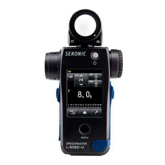
Names and Functions of Parts Names of Parts ❶ Lumisphere Retracting Ring ❷ Lumisphere ❸ Objective Lens ❹ (with diopter adjustment) ❺ ❻ ❼ ❽ ❾ ❿ ⓫ ⓬ Synchro Terminal ⓭ ⓮ ⓯ ⓰ Strap Eyelet Tabs (Three) Lumisphere Lock Extended Mark Lever ⓴... -
Page 17: Functions Of Parts
Functions of Parts The following table lists the functions of each part. Part Name Function Lumisphere Retracting Turn this to switch between the extended lumisphere and ❶ Ring retracted lumisphere. ( P35) Position the meter at subject with Lumisphere facing toward ❷... -
Page 18: Before Use
Before Use Attaching the Strap Eyelet ⓰ Pass the opposite end of the strap through the loop at the end of the strap. Strap Eyelet ⓰ Strap WARNING Infants or toddlers may accidentally wrap the strap around their neck, so CAUTION Infants or toddlers may accidentally grasp and swing the strap, so please place it in a location out of their reach. - Page 19 Inserting the Batteries Prepare two AA batteries. ⓯ ⓮ Unlock the Battery Cover Latch , and remove the Battery Cover Insert the batteries according to the "+" and "–" symbols in the ⓴ Battery Compartment ⓮ to the holes ⓮ of the meter.
- Page 20 Power ON Press the Power Button ❺ The meter turns on. The Startup Screen appears on the LCD for ❺ one second. Then operating assignment for the ❻ Measuring Button Memory Button ❼ on the Measuring Screen for two seconds. ❼...
- Page 21 NOTICE The blue lettered "SEKONIC" Logo Screen is displayed after battery replacement and 24 hours after power OFF. progress bar is moving on the Logo Screen, so please do not turn OFF the power, as doing so may lead to damage.
- Page 22 button is pressed. NOTE All settings and measurements are saved in memory even ❺ The graph displayed during the Flash Duration Analysis Mode ❺ ( P189) ❺ is inadvertently and and then automatically turn OFF to save battery power.
- Page 23 Measuring Screen Adequate battery life remaining. Indicator Have a spare battery ready. Replace the battery immediately. NOTE should be replaced immediately. It is recommended that spare batteries be kept on hand. 15 hours (based on Sekonic testing methods). Replacing Batteries them.
-
Page 24: Screen Operations
3. Screen Operations Screen Operations Basic Operations ( P191)) Touch operations Touch each icon to change the display to a desired screen. ( P44) Measuring Screen Measuring Mode Screen optional accessory installed. Measuring Screen If you touch the arrow icon ( increase the setting value or change to an item above. - Page 25 3. Screen Operations Slide operations Setting Value Areas areas at any time to change setting values. slide it to change the setting value. Touch and move the slider to change the setting Slider value on the scale. Radio button operations Set Filter Compensation Screen Touching a Radio button selects the item to the right of it.
- Page 26 3. Screen Operations The input value is displayed in this area. ② ① ③ ④ Description 0-9, Decimal ① point, Sign displayed at the top of the screen. ② Deletes the input value. ③ ④ Cancel...
- Page 27 3. Screen Operations Character Input Screen Upper Case Input Screen ① ④ ⑤ ② ⑥ ⑦ ③ Lower Case Input Screen How to input characters and numbers Description ① The cursor indicates the location at which to input a value. ABC, abc, 0-9, Decimal ②...
-
Page 28: Locking And Unlocking The Screen
3. Screen Operations Locking and Unlocking the Screen You can lock the screen to prevent misoperation. ❺ ❻ ❼ still operational. Measuring Screen Measuring Screen operations in locked state) Lock ❾ on the Measuring Screen to lock the screen (the [Locked] screen). -
Page 29: Screen Transition
3. Screen Operations Screen Transition The basic screen transition is as follows. A change in the Measuring Mode or settings can be made on the Measuring Screen. Power ON Measuring Mode Startup Screen ( P175) Set the Measuring Mode that matches your intended use. -
Page 30: Screen Display
3. Screen Operations Screen Display 3-4-1 Measuring Screen Screen has been displayed for one second. * This example of the Measuring Screen shows all the items for explanation purposes. The values shown are not defaults. installed. Measuring Screen item list Name Description Status Bar... - Page 31 3. Screen Operations Name Description Displays information such as measured values and measuring units. Measuring Unit Display Area Displays the additional data for the measured value. ( P183) Displayed when "Select Incident/Spot" is not assigned to Function Spot ( P33) Analog Scale depending on the Measuring Mode.
- Page 32 3. Screen Operations Status bar This example shows all the items for explanation purposes. The displayed information vary depending on settings. Displayed item list Name Description Full battery power remaining. Battery Capacity Indicator Low battery power remaining. Have spare batteries ready. Display Replace the batteries immediately.
-
Page 33: Measuring Operation/Display Area
3. Screen Operations 3-4-2 The measuring operation/display area consists of the following components: Measuring Mode Icon Setting Value Icon Measured value/measuring unit display area Analog scale Measuring Mode Icon Setting Value Icon (Ambient Mode) Measured Value/Measuring Unit Display Area Analog Scale Measuring Mode Measuring Mode Icon Touch the [Measuring Mode] Icon (... - Page 34 3. Screen Operations The setting value is displayed in the icon. The displayed icon varies depending on the Measuring Mode. Measuring Screen Mode, Flash Measuring Mode Mode Priority Mode HD CINE Mode CINE Mode * The character on the upper-left side of the Setting Value Icon indicates the setting.
- Page 35 3. Screen Operations Displays information such as measured values and measuring units. Measuring Screen Unit of Measured Value: ISO (ISO sensitivity) Measured Value Measured Value/ Measured Value Measuring Unit (Additional data display) Display Area Measuring Mode information display : Ambient light illuminance lx independent display cd/m : Ambient light luminance (cd/m ) independent display...
- Page 36 3. Screen Operations Measuring Screen Unit of Measured Value: F (aperture) Flash component: The ratio of Measured Value/ Measuring Unit is displayed as a percentage Display Area Measured Value NOTE Display in Measuring Screen Fraction hidden Fraction displayed Fraction hidden Fraction displayed...
- Page 37 3. Screen Operations Analog scale The analog scale displays the exposure setting for a current measurement and value relationships between two or more memorized measurements. Memory Pointer Memory Pointer Measured Value Pointer Measured value scale scale. Aperture scale Shutter speed scale ) scale This scale has two modes that can be selected: measured value scale and EV scale.
- Page 38 3. Screen Operations Flash analyzing scale whether to display components or not. ( P74) Ambient Light (Orange) Component displayed No component displayed Mid tone scale point and dynamic range are displayed. ( P143) Measuring display Measuring display Dynamic Dynamic Range [-] Point 3-4-3 USB Connection Screen...
- Page 39 3. Screen Operations 3-4-4 Name Description Measured value ① Displays the measured value. display ② Additional display Displays only the plus or minus sign when exposure compensation ③ compensation is set for the actually measured exposure value. Appears when the shutter speed is set in minutes. ④...
- Page 40 3. Screen Operations multiplier symbol. multiplier symbol.
- Page 41 3. Screen Operations 3-4-5 ) on the Measuring Screen to make the following settings. Function Screen Measuring Screen To next page Compensation Spot Screen Screen Filter Compensation Set Mid. Tone Screen Screen Mid. Tone Clear Mid. Tone Recall Screen Screen...
- Page 42 3. Screen Operations Memory Clear Screen Memory Recall Screen Page 2 Multi Clear Flash Duration Analysis Page 2 Screen (sold separately) is installed.
- Page 43 3. Screen Operations Name Description ( P121) Function Select the light receiving method (Incident/Spot). ( P32) Input an Exposure compensation value. The allowable Compensation ( P128) Filter Compensation ( P131) Set the mid-tone (from the current measured value or Set Mid. Tone memorized value) or edit the mid tone value.
-
Page 44: Menu Screen
3. Screen Operations 3-4-6 Menu Screen ❾ to make the following settings. Custom Setting Menu Analog Scale Screen Screen ❾ Menu Screen Edit Frame Rate Page 1 Screen Screen Edit Shutter Angle Screen Edit Filter Screen Menu Screen Page 2 Product Information Screen * The contents on the Regulation... - Page 45 3. Screen Operations Menu item list Name Description Analog Scale Set the display of the analog scale. ( P22) Select a function or set and edit the displayed information. Custom Setting Menu meter side (about setting values and names). ( P152) Edit Frame Rate rates.
-
Page 46: Basic Operations
Basic Operations Power ON P35) Incident light Switch the light receiving P32) Retracted lumisphere P35) method P32) • P37) P48) • F P51) Ambient light Select a Measuring • P48) Mode P44) Priority Mode P53) • HD CINE Mode P55) •... -
Page 47: Switch The Light Receiving Method
Switch the Light Receiving Method 4-2-1 Incident Light System The incident light system measures the light that is falling on the subject using the Extended lumisphere or Retracted Lumisphere Function. Point the lumisphere at the camera lens (lens optical axis) from a location Using the Function Button for Setting system to the incident light system. - Page 48 NOTICE If you used Custom Functions to change the Function Measuring Screen P34) NOTE Icon Description Displayed when the extended lumisphere is selected for incident light. Displayed when the retracted lumisphere is selected for incident light.
- Page 49 ) on the Measuring Screen. Touch the [Incident Light] Radio Button. This changes the system to the incident light system, and the display returns to the Measuring Screen. Measuring Screen. Measuring Screen Measuring Screen NOTICE Measurement values for the current Measuring Mode will be cleared when going to...
-
Page 50: Interchanging The Extended Lumisphere And Retracted Lumisphere
Lumisphere three dimensional subjects. Rotate the top of the Lumisphere Retracting Ring ❶ to securely align the mark on the ring with the lumisphere mark ( 2. Retracting Lumisphere and simply measure the illuminance. Rotate the Lumisphere Retracting Ring ❶ to securely align the mark on the ring with the retracted lumisphere mark ( Lumisphere Retracting Ring... - Page 51 NOTE Lumisphere If the Lumisphere ❷ Retracting Ring ❶ replace the defective lumisphere with the new one. 1) How to replace the Lumisphere ❷ Push down the Lumisphere Lock Lever . While holding both the upper and lower parts of Lumisphere Retracting Ring ❶...
- Page 52 4-2-2 system measures the brightness (luminance) of the light measured at the camera position or in the camera direction. Using the Function Button for Setting * This section describes how to switch the light receiving method from the incident light ) on the Measuring Screen.
- Page 53 NOTICE If you used Custom Functions to change the Function Measuring Screen P39) NOTE Icon Description Displayed when the extended lumisphere is selected for incident light. Displayed when the retracted lumisphere is selected for incident light.
- Page 54 ) on the Measuring Screen. Screen. Measuring Screen. Measuring Screen Measuring Screen NOTICE Measurement values for the current Measuring Mode will be cleared when going to...
- Page 55 Measuring Area The measuring area is the inside of circle in the The light receiving angle is 1 degree. Diopter Scale Compensation ❹ ❹ so that the circle and digital display can be seen clearly. WARNING Be careful not to directly look at the sun or bright light sources during measurement.
-
Page 56: ❻ ❼
❻ ❼ 4-2-3 Setting the Measuring Button and Memory Button ❻ ❼ ( P173) ❺ 1. When mainly using the incident light system Memory Measuring ❼ ❻ NOTE Right after the setting is changed and returning to Measuring Measuring Screen seconds. - Page 57 NOTE Right after the setting is changed and returning to Measuring Measuring Screen seconds. ( P173) Auto Spot: Reverse) Memory Memory Measuring Measuring In Incident Light System...
- Page 58 4. When inactivating the Memory Button ( P193) ❼ NOTE Right after the setting is changed and returning to Measuring Measuring Screen ❺ will be displayed for two seconds. not function.
-
Page 59: Selecting The Measuring Mode
Selecting the Measuring Mode Select the desired Measuring Mode. NOTICE If you change the Measuring Mode, the measured value is cleared. Touch the [Measuring Mode] Icon ( ) on the Measuring Screen to display the Measuring Mode Screen. Here you can select any Measuring Mode to suit your light measuring needs. - Page 60 Ambient Light CINE Mode ⑤ values. ( Displays brightness value in lux (lx) unit. ( Displays brightness value in foot-candle (fc) unit. ( ⑥ Displays brightness values in cd/m unit. ( P72) ( P72) NOTE Ambient Light refers to natural light (sunlight) as well as continuous light like tungsten Measuring Mode: Flash Mode ( P177) Icon Description...
- Page 61 ⑫ F-stop value for input shutter speed and ISO sensitivity (When a transmitter sold separately is installed). ( P92) Measuring Mode: HSS Mode ( P179) Icon Description ⑬ ISO sensitivity. ( P93) Speed Synchro) Flash Mode. ⑭ for input shutter speed and ISO sensitivity (When a transmitter sold separately is installed).
- Page 62 Operation * This section describes how to switch from the Ambient T Priority Mode to the Touch the [Measuring Mode] Icon on the upper left of the screen. The Measuring Mode Screen is displayed. Measuring Screen Measuring Mode Screen [Measuring Mode] Icon Touch the desired icon on the Measuring Mode Screen.
-
Page 63: Measuring
5. Measuring Measuring Measuring in Ambient Light Mode The following measuring methods are available in Ambient Light Mode. T (shutter speed) priority F (f-stop) priority Illuminance Mode (Lux or Foot-candle) (in incident light measurement) Luminance Mode (cd/m NOTE ) at the bottom of the screen activates the Average Function. -
Page 64: T (Shutter Speed) Priority Mode
5. Measuring 5-1-1 Displays the measured value (F-stop) for input ISO sensitivity and shutter speed values. Operation Touch the [Measuring Mode] Icon on the Measuring Screen. The Measuring Mode Screen is displayed. ) on the Measuring Mode Screen. When it is selected, the display changes to the Measuring Screen. Measuring Screen Measuring Mode Screen Measuring Screen... - Page 65 5. Measuring Set the ISO sensitivity value on the [ISO] Icon. P207) Set the shutter speed on the [T] Icon. P207) Measuring Screen Setting Value ❻ Press the Measuring Button on the side of the meter to measure the light. ❻...
- Page 66 5. Measuring 5-1-2 Displays the measured value (shutter speed) for input ISO sensitivity and F-stop values. Operation Touch the [Measuring Mode] Icon on the Measuring Screen. The Measuring Mode Screen is displayed. ) on the Measuring Mode Screen. When it is selected, the display changes to the Measuring Screen. Measuring Screen Measuring Mode Screen Measuring Screen...
- Page 67 5. Measuring Set the ISO sensitivity value on the [ISO] Icon. P207) P207) Measuring Screen Setting Value ❻ Press the Measuring Button on the side of the meter to measure the light. ❻ the button is released. ❻ measured value at that time will be displayed in the measured value/measuring unit display area and on the analog scale.
- Page 68 5. Measuring 5-1-3 Displays the measured value (ISO sensitivity) for input shutter speed and F-stop values. appropriate exposure. Operation Touch the [Measuring Mode] Icon on the Measuring Screen. The Measuring Mode Screen is displayed. ) on the Measuring Mode Screen. When it is selected, the display changes to the Measuring Screen.
- Page 69 5. Measuring Set the shutter speed on the [T] Icon. P207) P207) Measuring Screen Setting Value ❻ Press the Measuring Button to measure the light on the side of the meter. The measured ISO sensitivity value will be displayed. ❻ the button is released.
-
Page 70: Measuring
5. Measuring 5-1-4 HD CINE Mode frame rate (f/s). Measuring Operation Touch the [Measuring Mode] Icon on the Measuring Screen. The Measuring Mode Screen is displayed. ) on the Measuring Mode Screen. When it is selected, the display changes to the Measuring Screen. Measuring Screen Measuring Mode Screen Measuring Screen... - Page 71 5. Measuring Set the ISO sensitivity value on the [ISO] Icon. P207) Touch the [ISO] Icon to expand it. The icon will return to its reduced size after the icon is not touched for a short time. Measuring Screen Touch the [f/s] Icon to expand it. The icon will return to its reduced size after the icon is not touched for a short time.
- Page 72 5. Measuring Press the Measuring Button ❻ on the side of the meter to measure the light. ❻ the button is released. ❻ measured value at that time will be displayed in the measured value/measuring unit display area and on the analog scale. ( P22 P24) Measuring Screen Measured Value (F-stop) NOTE...
-
Page 73: Frame Rate Editing
5. Measuring Frame Rate Editing customized and displayed in the Meter Screen. The stored frame rates can be edited as desired. ( Menu Screen, Page 1 Edit Frame Rate Edit Frame Rate Screen Page 1 Page 2 Page 3 Page 4 To next page To next page To next page... - Page 74 5. Measuring Touch [Edit Frame Rate] Button to display the Edit Frame Rate Screen. Touch [Frame Rate] Button to display the Frame Rate Screen. Menu Screen Edit Frame Rate Frame Rate Screen Page 1 Screen Input a numeric value in the Input Frame Rate Screen. P11) Touch [OK] Button.
- Page 75 5. Measuring Touch the box ( ) to check it (check mark ). The checked frame rate is displayed Edit Frame Rate Screen The input numeric value is displayed. To next page Measuring Screen Measuring Screen Touch [Close] Button on the Edit Frame Rate Screen. The display returns to the Menu Screen.
- Page 76 5. Measuring 5-1-5 CINE Mode shutter angle (Ang). Measuring Operation Touch the [Measuring Mode] Icon on the Measuring Screen. The Measuring Mode Screen is displayed. ) on the Measuring Mode Screen. When it is selected, the display changes to the Measuring Screen. Measuring Screen Measuring Mode Screen Measuring Screen...
- Page 77 5. Measuring Set the ISO sensitivity value on the [ISO] Icon. P207) Touch the [ISO] Icon to expand it. The icon will return to its reduced size after the icon is not touched for 3 seconds. Measuring Screen Set the shutter angle on the [Ang] Icon. Touch the [Ang] Icon to expand it.
- Page 78 5. Measuring Press the Measuring Button ❻ on the side of the meter to measure the light. ❻ the button is released. ❻ measured value at that time will be displayed in the measured value/measuring unit display area and on the analog scale. ( P22 P24) Measuring Screen Measured Value (F-stop) NOTE...
- Page 79 5. Measuring Frame Rate Editing customized and displayed in the Meter Screen. The stored frame rates can be edited as desired. Menu Screen, Page 1 Edit Frame Rate Edit Frame Rate Screen Page 1 Page 2 Page 3 Page 4 To next page To next page To next page...
- Page 80 5. Measuring Touch [Edit Frame Rate] Button to display the Edit Frame Rate Screen. Touch [Frame Rate] Button to display the Frame Rate Screen. Menu Screen Edit Frame Rate Frame Rate Screen Page 1 Screen Input a numeric value in the Input Frame Rate Screen. P11) Touch [OK] Button.
- Page 81 5. Measuring Touch the box ( ) to check it (check mark ). The checked frame rate is displayed Edit Frame Rate Screen The input numeric value is displayed. To next page Measuring Screen Measuring Screen Touch [Close] Button on the Edit Frame Rate Screen. The display returns to the Menu Screen.
- Page 82 5. Measuring Shutter Angle Editing can be customized and displayed in the Meter Screen. The input shutter angle can be edited as desired. Menu Screen, Page 1 Edit Shutter Angle Edit Shutter Angle Screen Page 1 Page 2 Page 3 Page 4 To previous page To next page...
- Page 83 5. Measuring Touch the [Edit Shutter Angle] Button. The Edit Shutter Angle Screen is displayed. Touch the [Shutter Angle] Button. The Input Shutter Angle Screen is displayed. Menu Screen Edit Shutter Angle Screen Shutter Angle Screen Page 1 Input a numeric value on the Input Shutter Angle Screen. P11) Touch [OK] Button.
- Page 84 5. Measuring Touch the box ( ) to check it (check mark ). The checked shutter angle is displayed When checked (check mark Edit Shutter Angle Screen The input numeric value is displayed. To next page Measuring Screen Measuring Screen Touch the [Close] Button on the Edit Shutter Angle Screen.
- Page 85 5. Measuring 5-1-6 The following are the units that can be set. Select the Illuminance/Luminance Unit in Lux (Unit: lx) Incident light measurement Foot-candle (Unit: fc) ( P72) NOTE or luminance. Illumination Measuring Operation Switch the light receiving method to incident light. P32) Touch the [Measuring Mode] Icon on the Measuring Screen.
- Page 86 5. Measuring Switch to the retracted lumisphere. ❶ to switch to the retracted lumisphere ( ) position. Measuring Screen Lumisphere Retracting Ring ❶ Retracted Mark ( Point the light receptor directly toward the light source. Press the Measuring Button ❻ on the side of the meter to measure the light.
-
Page 87: Luminance Measuring
5. Measuring Luminance Measuring Operation P37) Touch the [Measuring Mode] Icon on the Measuring Screen. The Measuring Mode Screen is displayed. ) on the Measuring Mode Screen. When it is selected, the display changes to the Measuring Screen. Measuring Screen Measuring Mode Screen Measuring Screen [Measuring... - Page 88 5. Measuring ❻ on the side of the meter to measure the light. ❻ meter (measured value). ❻ the button is released. ❻ measured value at that time will be displayed in the measured value/measuring unit display area and on the analog scale. ( P22 P24) Measuring Screen Measuring Screen Measured Value (cd/m...
-
Page 89: Measuring In Flash Light Mode
5. Measuring Measuring in Flash Light Mode Flash illumination is light that is produced by the very brief light pulse of an modes: Radio Triggering Flash Mode *Available when a transmitter (sold separately) is installed separately) is installed Screen Display Details exposure) is displayed on the screen. -
Page 90: Measuring
5. Measuring NOTE display the corresponding aperture. ) at the bottom of the screen ( P121) and Mid-Tone Mode selected as well as "Set Analog Scale" (Measurement Scale or EV Scale) in Menu list. ( P22) aperture or adjust the brightness. ( P111) 5-2-1 Cordless Flash Mode ❻... - Page 91 5. Measuring Set the light receiving method. )/retracted lumisphere ( P32 P37) Set the ISO sensitivity value on the [ISO] Icon. P207) Set the shutter speed on the [T] Icon. P207) Measuring Screen Setting Value NOTICE Press the Measuring Button ❻...
- Page 92 5. Measuring ) is blinking. Measuring Screen Measured Value (F-stop) NOTICE In case of the following, please follow "5-2-3 Cord Flash Mode". P86) meter may fail to detect the light. receptor, measurement may be made. NOTE for three seconds after measurement. canceled.
- Page 93 5. Measuring Operation ) on the Measuring Screen. Mode. Measuring Screen Page 1 Page 2 To next page...
- Page 94 5. Measuring The display returns to the Measuring Screen. Screen. NOTE...
- Page 95 5. Measuring 5-2-2 until the desired F-stop value is displayed. ❻ sensitivity is displayed. Measuring Operation Touch the [Measuring Mode] Icon on the Measuring Screen. The Measuring Mode Screen is displayed. ) on the Measuring Mode Screen. When it is selected, the display changes to the Measuring Screen. Measuring Screen Measuring Mode Screen Measuring Screen...
- Page 96 5. Measuring Set the ISO sensitivity value on the [ISO] Icon. P207) Set the shutter speed on the [T] Icon. P207) Measuring Screen Setting Value NOTICE ❻ Press the Measuring Button The meter will enter the Measuring Standby Mode, and the [Measuring Mode] Icon ) will blink for 90 seconds.
- Page 97 5. Measuring ) is blinking. Measuring Screen Measured Value (F-stop) NOTICE In case of the following, please follow "5-2-4 Mode". P88) ambient light, the meter may fail to detect the light. receptor, measurement may be made. NOTE and is only illuminated for three seconds after measurement. Standby Mode again.
- Page 98 5. Measuring Multi Clear Operation ) on the Measuring Screen. This button is only enabled during measurement. count cannot be cleared. The multiple cumulate value is cleared, and the display returns to the Measuring Screen. Measuring Screen. Measuring Screen Page 1 Page 2 To next page Measuring Screen...
- Page 99 5. Measuring NOTE ❻ Operation ) on the Measuring Screen. This button is enabled if Flash Mode is selected. Measuring Screen Page 1 Page 2 To next page...
- Page 100 5. Measuring The display returns to the Measuring Screen. Screen. NOTE...
- Page 101 5. Measuring 5-2-3 Cord Flash Mode ❻ F-stop value for input shutter speed and ISO sensitivity. Operation separately), which is connected to P204) ⓬ the meter's Synchro Terminal Touch the [Measuring Mode] Icon on the Measuring Screen. The Measuring Mode Screen is displayed. ⓬...
- Page 102 5. Measuring Set the ISO sensitivity value on the [ISO] Icon. P207) Set the shutter speed on the [T] Icon. P207) Measuring Screen Setting Value NOTICE Press the Measuring Button ❻ Measuring Screen Measured Value (F-stop) NOTICE ⓬ When the synchro cord is connected to the Synchro Terminal or when the meter's Power Button ❺...
- Page 103 5. Measuring 5-2-4 value (F-stop) for input shutter speed and ISO sensitivity is displayed. The Measuring Operation separately), which is connected to P204) the meter's Synchro Terminal ⓬ Touch the [Measuring Mode] Icon on the Measuring Screen. The Measuring Mode Screen is displayed. Synchro Terminal ⓬...
- Page 104 5. Measuring Set the ISO sensitivity value on the [ISO] Icon. P207) Set the shutter speed on the [T] Icon. P207) Measuring Screen Setting Value NOTICE ❻ Press the Measuring Button will be displayed. Press the Measuring Button ❻ until the desired F-stop is displayed.
- Page 105 5. Measuring NOTE ❼ Multi Clear Operation ) on the Measuring Screen. This button is only enabled during measurement. count cannot be cleared. The multiple cumulate value is cleared, and the display returns to the Measuring Screen. Measuring Screen. Measuring Screen Page 1 Page 2 To next page...
- Page 106 5. Measuring Measuring Screen Multiple Cumulative Count 5-2-5 Radio Triggering Flash Mode ❻ is pressed to send radio Measuring Screen Measuring Mode Screen Measuring Screen [Measuring Mode] Icon...
- Page 107 5. Measuring 5-2-6 the desired F-stop value is displayed. ❻ is pressed to send measured value (F-stop) for input ISO sensitivity and shutter speed is displayed. In measurement is available). Measuring Screen Measuring Mode Screen Measuring Screen [Measuring Mode] Icon NOTE ❼...
- Page 108 5. Measuring HSS (High Speed Synchro) Flash measurement is available in the following modes: ・ ・HSS (High Speed Synchro) Flash Radio Triggering Mode (with RT-GX installed) 5-3-1 ❻ speed and ISO sensitivity is displayed. Measuring Operation Touch the [Measuring Mode] Icon on the Measuring Screen. The Measuring Mode Screen is displayed.
- Page 109 5. Measuring Set the light receiving method. )/retracted lumisphere ( P32 P37) Set the ISO sensitivity value on the [ISO] Icon. P207) Set the shutter speed on the [T] Icon. P207) Measuring Screen Setting Value NOTICE Press the Measuring Button ❻...
- Page 110 5. Measuring ) is blinking, release the shutter Measuring Screen Measured Value (F-stop) NOTE illuminated for three seconds after measurement. Standby Mode again. can be accomplished by mounting the meter on a tripod or stand using the tripod socket on the bottom of the meter. Operation ) on the Measuring Screen.
- Page 111 5. Measuring Mode. ( P45) Measuring Screen Page 1 Page 2 To next page The display returns to the Measuring Screen. NOTE...
- Page 112 5. Measuring 5-3-2 ❻ is pressed to send This measuring mode is available only when the RT-GX (sold separately) is installed on the meter. Measuring Screen Measuring Mode Screen Measuring Screen [Measuring Mode] Icon...
- Page 113 5. Measuring Measuring in Flash Duration Analysis Mode waveform can be measured for input shutter speed and ISO sensitivity. Flash Duration Analysis is performed with incident light Measuring Mode only. Flash duration measurement is available in the following modes: Flash Duration Analysis Radio Triggering Mode *Available when a transmitter (sold separately) is installed 5-4-1 Flash Duration Analysis Cordless Mode...
- Page 114 5. Measuring Set the light receiving method. Incident light system Switch to the extended lumisphere ( )/retracted lumisphere ). ( P32) Set the ISO sensitivity value on the [ISO] Icon. P207) Set the shutter speed on the [T] Icon. P207) Measuring Screen Setting Value NOTICE...
- Page 115 5. Measuring ) is blinking. Measuring Screen Flash Duration Time Measured Value (F-stop) NOTICE In case of the following, please follow "5-4-2 Flash Duration Analysis Code Mode". P105) meter may fail to detect the light. receptor, measurement may be made. Mode, however, they cannot be stored in the memory.
- Page 116 5. Measuring NOTE previous screen. Flash Duration Analysis Cordless Mode Flash Waveform Graph Screen Measuring Screen Touching the Measured value area changes the display. * The Graph Screen cannot be used to make measurements. can be accomplished by mounting the meter on a tripod or stand using the tripod socket on the bottom of the meter.
- Page 117 5. Measuring Measuring Screen Page 1 Page 2 To next page The display returns to the Measuring Screen. Screen. NOTE...
- Page 118 5. Measuring Operation ) on the Measuring Screen. check the Measuring Mode. Measuring Screen Page 1 Page 2 To next page...
- Page 119 5. Measuring Input the "Reference" of 0.1 to 0.9 by touching the numeric value. Flash Duration Analysis Flash Duration Analysis The input numeric value is displayed. Touch [OK] Button. The setting is input, and the display returns to the Measuring Screen. Measuring Screen NOTE...
- Page 120 5. Measuring 5-4-2 Flash Duration Analysis Code Mode ❻ measured for input shutter speed and ISO sensitivity. Measuring Operation separately), which is connected to P204) the meter's synchro terminal ⓬ Touch the [Measuring Mode] Icon on the Measuring Screen. Synchro Terminal ⓬...
- Page 121 5. Measuring Set the ISO sensitivity value on the [ISO] Icon. P207) Set the shutter speed on the [T] Icon. P207) Measuring Screen Setting Value NOTICE Measuring Screen input shutter speed, an appropriate F-stop cannot be measured. The yellow "Under" indication appears. duration time and measure again.
- Page 122 5. Measuring NOTICE Mode, however, they cannot be stored in the memory. They are cleared if the Measuring Mode is changed or the POWER switch is turned OFF. The incident light measurement can only be used in Flash Duration Analysis Mode. When the synchro cord is connected to the Synchro Terminal ⓬...
- Page 123 5. Measuring Operation ) on the Measuring Screen. check the Measuring Mode. Measuring Screen Page 1 Page 2 To next page...
- Page 124 5. Measuring Input the "Reference" of 0.1 to 0.9 by touching the numeric value. Flash Duration Analysis Flash Duration Analysis The input numeric value is displayed. Touch [OK] Button. The setting is input, and the display returns to the Measuring Screen. Measuring Screen NOTE...
- Page 125 5. Measuring 5-4-3 Flash Duration Analysis Radio Triggering Mode ❻ is pressed to send radio Measuring Screen Measuring Mode Screen Measuring Screen [Measuring Mode] Icon...
- Page 126 5. Measuring Out of Displayed Range or Measuring Range 5-5-1 take the following actions. again. The correct F-stop will be displayed for input values. again. The correct F-stop will be displayed for input values. NOTE each measurement mode in "5. Measurement" ( P48) .
- Page 127 5. Measuring 5-5-2 "Under" will appear and blink. level and measure again. When brightness is under the When brightness is over the measuring range measuring range NOTE Display Range Ambient light Incident light system -5EV to EV22.9...
-
Page 128: F (Aperture) Priority Mode
Functions Memory Function This meter can save measured values in the memory. This function is available in the following Measuring Modes. Ambient Mode T Priority Mode F Priority Mode TF Priority Mode Flash Mode Radio Triggering Mode HSS Flash Mode HSS Flash Radio Triggering Mode You can save (in the memory) and recall up to nine measured values regardless of NOTE... - Page 129 6-1-1 Operation Press the Measuring Button ❻ The measured value at that time will be displayed. ❻ make measurements. ❻ value at that time will be displayed in the measured value/measuring unit display area and on the analog scale. ( P22 P24) Press the Memory Button ❼...
- Page 130 NOTICE The Memory Function cannot be used in the following Measuring Modes. Flash Duration Analysis Cordless Mode Flash Duration Analysis Cord Mode Flash Duration Analysis Radio Triggering Mode NOTE Memory count warning Measuring Screen Up to nine measured values can be saved in the memory. If measured value cannot be saved in the memory.
- Page 131 6-1-2 Memory Clear This function individually or collectively clears measured values that are saved in in which they are saved in the memory. Measured values that are saved in the memory are displayed as dots ( ) on the analog scale. Operation ) on the Measuring Screen.
- Page 132 Individual Clear Operation Select the memory value to be deleted on the Memory Clear Screen. Multiple memory values are selectable. Touch [Clear] Button. the "Selected memory is cleared. Are you sure?" message is displayed. clearing the memory value. Touch [OK] Button. The selected item is cleared, and the display returns to the Memory Clear Screen.
- Page 133 Collective Clear The measured values that are saved in the memory can be cleared collectively. Operation Touch [ALL] Button on the Memory Clear Screen. memory is cleared. Are you sure?" message is displayed. Touch [OK] Button. All the memory values are cleared, and the display returns to the Measuring Screen.
- Page 134 6-1-3 Memory Recall This function recalls the measured values that are saved in the memory to enable the user to view details. This screen displays memory information incident light ( in the order in which they are saved in the memory. Measured values that are saved in the memory are displayed as dots ( ) on the analog scale.
- Page 135 Touch the item to be recalled. background) Memory Recall Screen Recall Screen Recalled Memory NOTE even if the mode is switched. Values saved in the memory in each Measuring Mode are displayed in the value type corresponding to the measurement mode in which memory recall was carried out.
- Page 136 Touch [Memory Recall] Button. If you touch [Memory Recall] Button on the Recall Screen to display another memory value, the display returns to the Memory Recall Screen. returning to the Memory Recall Screen. Touch [Close] Button. If you touch [Close] Button, the display returns to the Measuring Screen instead of returning to the Memory Recall Screen.
- Page 137 Operation Measuring ❻ ❻ Press the Measuring Button Press this button to make a measurement. ❼ Press the Memory Button The measured value is saved in the memory. Each measured value that is saved in the memory is displayed Memory ) on the analog scale.
- Page 138 NOTE The Average Function can be used only in the modes that the memory function is valid. ( P127). ) again. ) returns to ). Then, the "Ave" symbol disappears from the screen. The last measured value is displayed. Measuring Screen Measuring Screen NOTE Button...
- Page 139 Contrast Function This function is useful for checking studio lighting or illumination unevenness. This intermediate value and the highlight and/or shadow value for landscape shooting. ❻ at the comparison position after between the standard value and the value at the comparison position is displayed with an scale.
- Page 140 ) is highlighted ( Measuring Screen Measuring Screen Measured Reference Value Value Turn ON the second light source only. Turn OFF the main light source. ❻ Hold down the Measuring Button Point the light receptor at the second light source from the subject position to make a ❻...
- Page 141 Measuring Screen Measuring Screen Enlarge Analog Scale Measured Reference Value Value " EV" Symbol The Average Function is active. Illumination Ratio NOTE optical axis of the camera to make a measurement. ( P127). Function is valid. ( P113) ( P22)
- Page 142 Operation ) on the Measuring Screen. Touch the [ON] or [OFF] radio button or an area around an item name. If there are values in the memory, the standard value will be the average of all values saved in the memory. If there are no values in the memory, the standard value will be the last measured value.
- Page 143 Measuring Screen Measuring Screen "Ave" Symbol Function is "OFF" (When values in memory) (When values in memory) This function is useful when compensation is necessary for highlight and/or shadow Minus Compensation If a lighter image is obtained when shooting was carried out based on the measured darker value.
- Page 144 NOTE ( P171) NOTE Button Description Disabled when Exposure compensation is not set. Displayed when Exposure compensation is OFF. Operation ) on the Measuring Screen. Set the compensation value. P11 for details about how to input the value.) Touch [OK] Button. The display returns to the Measuring Screen, and the ( ) icon and the compensation value are displayed on the status bar.
- Page 145 Measuring Screen Input Value Value Measuring Screen Value...
- Page 146 Filter Compensation Function value is applied. value measured with the light meter. ) is displayed on the status bar. 2. Filter Pack in Use ) is displayed on the status bar. ) disappears from the status bar. NOTICE Note that this Filter compensation is applied in the incident light system and the NOTE Selecting the plus compensation decerases the exposure (the meter displays a higher shutter speed or F-stop).
- Page 147 6-4-1 Operation ) on the Measuring Screen. Screen. The Filter Compensation Screen is displayed. an item name. Measuring Screen Filter Compensation Page 1 Screen...
- Page 148 P11 for details about how to input the value.) Touch [OK] Button. The value is applied, and the display returns to the Filter Compensation Screen. Touch [OK] Button on the Filter Compensation Screen. The value is applied, and the display returns to the Measuring Screen. Then, the ) and the compensation value are displayed on the status bar.
- Page 149 6-4-2 Selecting a Filter Operation ) on the Measuring Screen. Screen. The Filter Compensation Screen is displayed. Touch [Filter Pack in Use] radio button or an area around an item name. The Filter Pack in Use Screen is displayed. Measuring Screen Filter Compensation Page 1 Screen...
- Page 150 Touch any of four [Filter Name] Buttons on the Filter Pack in Use Screen. The Select User Filter Screen is displayed. pages. ( Touch the radio button on the Filter Pack in Use Screen to select Screen. Filter Pack in Use Select User Filter Filter Pack in Use Screen...
- Page 151 Touch [OK] Button on the Filter Compensation Screen. The value is applied, and the display returns to the Measuring Screen. Then, the ) and the compensation value are displayed on the status bar. Filter Compensation Screen Measuring Screen Filter Filter Display NOTE See "...
- Page 152 6-4-3 values can be edited freely. Menu Screen Edit Filter Edit Filter Page 1 Page 1 Page 2 Edit Filter To next page To next page Edit Filter Edit Filter Edit Filter Page 3 Page 4 Page 5 To next page To next page To previous page...
- Page 153 Operation ❾ Press the Menu Button on the meter. The Menu Screen is displayed. Touch the [Edit Filter] Button. The Edit Filter Screen is displayed. ❾ The Edit Filter Screen is displayed. Menu Screen Edit Filter Screen Edit Filter Screen Page 1 Touch the [Filter Name] Button on the Edit Filter Screen.
- Page 154 P12) Touch [OK] Button. The display returns to the Edit Filter Screen. Filter Name Screen Displays the alphanumeric characters you entered. Edit Filter Screen...
- Page 155 P11) Touch [OK] Button. The display returns to the Edit Filter Screen. Displays the numeric value you entered. NOTICE displays a higher value of shutter speed or F-stop). Selecting the minus shutter speed or F-stop). Touch [Close] Button on the Edit Filter Screen. The display returns to the Edit Filter Screen.
- Page 156 Touch the box ( ) to check (check mark ( P134) listed. Edit Filter Screen Select User Filter Screen Touch [Close] Button on the Edit Filter Screen. The display returns to the Menu Screen. Touch [Close] Button on the Menu Screen. The display returns to the Measuring Screen.
- Page 157 6-4-4 Deselecting a Filter Operation ) on the Measuring Screen. The Filter Compensation Screen is displayed. Touch [No Filter] radio button or an area around an item name. "No Filter" is selected. Measuring Screen Filter Compensation Screen Touch [OK] Button on the Filter Compensation Screen. Screen.
- Page 158 Mid. Tone Function This function is used to specify a measured value as the standard of light measurements and put it at the center of EV scale. The Mid. Tone Function has four modes: Setting name Description Set from Current Specify the measured value as the Mid.
- Page 159 ) on the Measuring Screen. The Set Mid. Tone Screen is displayed. Touch the [Set from Current Measurement] Button on the Set Mid. Tone Screen. Set the current measured value as the Mid. Tone value, and return to the Measuring Screen. The newly set Mid. Tone value is then displayed on the analog scale.
- Page 160 Operation ) on the Measuring Screen. The Set Mid. Tone Screen is displayed. Touch the [Set from Memory] Button on the Set Mid. Tone Screen. This displays the Mid. Tone Set from Memory Screen, which shows memory ), and measured value). Measured values that are saved in the memory are displayed as dots on the analog scale.
- Page 161 Modify Current Mid. Tone Fine-tune the currently set Mid. Tone value. Operation ) on the Measuring Screen. The Set Mid. Tone Screen is displayed. Touch the [Modify Current Mid. Tone] Button on the Set Mid. Tone Screen. The Modify Current Mid. Tone Screen is displayed. Measuring Screen Set Mid.
- Page 162 ) or slide the number on the Modify Current Mid. Tone Screen. Select the desired Mid. Tone value. Touch [OK] Button. The change is applied and the display returns to the Measuring Screen. Modify Current Mid. Tone Modify Current Mid. Tone Measuring Screen Screen Screen...
- Page 163 6-5-2 Mid. Tone Recall Recall the set Mid. Tone value to view details. Operation ) on the Measuring Screen on The current Mid. Tone setting is displayed on the Measuring Screen. Touch [Close] Button. The display returns to the Measuring Screen. Measuring Screen Mid.
- Page 164 6-5-3 Mid. Tone Clear Operation ) on the Measuring Screen on which the Mid. Tone value is set. The Mid. Tone Clear Screen is displayed, and the message of "A Mid. Tone value is cleared. Are you sure?" is displayed. Touch [OK] Button.
- Page 165 Data Transfer Software is application software for creating and editing camera meter unit as well as for implementing all other related settings. Sensitivity characteristic Exposure area (wide) Measuring Screen curve Exposure area (intermediate) Exposure area (narrow) Target II Exposure Profile Target www.sekonic.com)
- Page 166 6-6-2 Operation ) on the Measuring Screen. Measuring Screen ) is displayed on the status bar. Page 1 Page 2 To previous page To next page NOTICE P152)
- Page 167 6-6-3 Menu Screen, Page 1 Edit Exposure Page 1 Page 2 To next page To previous page...
- Page 168 Operation ❾ Press the Menu Button on the meter. The Menu Screen is displayed. ❾ Menu Screen, Page 1 Touch the box ( ) to check it (check mark ). The selected item can be displayed mark ( not displayed on the screen. * Only the check box ( To next page...
- Page 169 Touch [Close] Button. The display returns to the Menu Screen. Menu Screen Touch [Close] Button on the Menu Screen. The display returns to the Measuring Screen. into the meter manually. Operation touch the check box ( ) to mark (check mark...
- Page 170 To next page Input the name. P12) Input the name here.
- Page 171 Touch [OK] Button. input is displayed. Touch the icon for the desired light receiving method and light [Light Receiving Method / Light Source] Icon NOTE Ambient Mode Flash Mode Ambient Mode Flash Mode...
- Page 172 edit. Touch the arrow icon ( Three buttons of ISO sensitivity that are able to be selected are displayed. Edit Screen [ISO Sensitivity] Edit the camera sensitivity characteristics. Set Camera Sensitivity Characteristic Screen (Synchronized with the cursor) Dynamic Range (-) ①...
- Page 173 ② Dynamic range and clipping point ③ Default is a convenient tool. Touch [OK] Button. Screen. Data Screen without changing any data. Touch [Close] Button on the ISO sensitivity selection on Edit Repeat steps 6 to 9. Edit another light receiving method and light source as needed. Edit Screen [Light Receiving...
- Page 174 The display returns to the Menu Screen. Touch [Close] Button on the Menu Screen. The display returns to the Measuring Screen. Menu Screen...
- Page 175 Custom Setting The meter can be customized to desired measuring and display preferences. Menu Screen, Page 1 Custom Setting Menu Page 1 To next page Custom Setting Menu Custom Setting Menu Custom Setting Menu Page 2 Page 3 Page 4 To next page To next page To previous...
- Page 176 6-7-1 Custom Setting List Custom Setting Default Setting Item Setting Name Average/ Average/ Incident/ Exposure Filter Function Mid. Tone All Memory/ Spot Button -1 Function Function Selection Average/ Incident/ Exposure Filter Incident/ Function Mid. Tone All Memory/ Spot Spot Button -2 Function Selection Selection...
- Page 177 Custom Setting Default Setting Item Setting Name Radio Triggering *4, *7 Mode *4, *6 d) Multi Mode HSS Flash Mode Cordless Mode Radio Triggering *4, *7 Mode Flash Duration Analysis Mode Cordless Mode b) Cord Mode Radio Triggering *4, *7 Mode Additional Illuminance /...
- Page 178 ❻ ❼ are placed in the standard selected. Flash Mode are available on the Measuring Mode Screen. Displayed if a transmitter RT-EL/PX (sold separately) is installed. The contents may See the transmitter operating manual for details.
- Page 179 6-7-2 Custom Setting Procedure Operation Press the Menu Button ❾ on the meter. The Menu Screen is displayed. Touch the [Custom Setting] Button. The Custom Setting Menu Screen is displayed. ❾ Custom Setting Menu Menu Screen, Page 1 Page 1 To next page Custom Setting Menu Custom Setting Menu...
- Page 180 Select the page to display the desired item to set. ) to display the target page. Touch the desired item name. The Item Setting Screen is displayed. Touch the radio button to select the desired item. Custom Setting Menu Function Button -1 Page 1 Page 1 Function Button -1 Setting...
- Page 181 Operation Touch the [Function Button -1] Button on page 1 of the Custom Setting Menu Screen. The Function Button -1 Screen is displayed. Touch the desired item. Touch the desired radio button or an area around the item name to select. Touch [Close] Button.
- Page 182 Function Button -2 Setting Measuring Screen Function Button -2 Screen Function Button -2 Screen Page 1 Page 2 To next page To previous page Operation Touch the [Function Button -2] Button on page 1 of the Custom Setting Menu Screen. The Function Button -2 Screen is displayed.
- Page 183 Touch [Close] Button on the Custom Setting Menu Screen. The display returns to the Menu Screen. Touch [Close] Button on the Menu Screen. The display returns to the Measuring Screen. on the Measuring Screen. Custom Setting Menu Screen Menu Screen Measuring Screen "Increments of T+F"...
- Page 184 Touch the desired item. Touch the desired radio button or an area around the item name to select. Touch [Close] Button. The display returns to the Custom Setting Menu Screen. Custom Setting Menu Screen Increments of T+F Screen Default Touch [Close] Button on the Custom Setting Menu Screen. The display returns to the Menu Screen.
- Page 185 Measuring Screen Measuring Screen Display of Increments Operation Custom Setting Menu Screen. Touch the desired item. Touch the desired radio button or an area around the item name to select. Touch [Close] Button. The display returns to the Custom Setting Menu Screen. Custom Setting Menu Screen Default...
- Page 186 Touch [Close] Button on the Custom Setting Menu Screen. The display returns to the Menu Screen. Touch [Close] Button on the Menu Screen. The display returns to the Measuring Screen, and the updated content is applied to the Measuring Screen. Custom Setting Menu Screen Menu Screen Operation...
- Page 187 Touch [Close] Button. The display returns to the Custom Setting Menu Screen. Custom Setting Menu Screen Default Touch [Close] Button on the Custom Setting Menu Screen. The display returns to the Menu Screen. Touch [Close] Button on the Menu Screen. The display returns to the Measuring Screen.
- Page 188 ❻ Setting for Switching the Measuring Button and Memory ❼ Button NOTE Standard: Used for measurement in the incident light system. Measuring Screen Memory Measuring Measuring Screen Measuring Memory Auto: The button arrangement is set to "Standard" when the incident light system is the power has been turned on.
- Page 189 Operation 1 of the Custom Setting Menu Screen. Touch the desired item. Touch the desired radio button or an area around the item name to select. Touch [Close] Button. The display returns to the Custom Setting Menu Screen. Custom Setting Menu Screen Memory Buttons Screen Default...
- Page 190 Ambient Mode Setting You can select Measuring Modes to be displayed on the Measuring Mode Screen. Measuring Mode Screen Measuring Mode Screen Measuring Mode Screen All OFF in Ambient Mode Individually OFF in Ambient Mode Operation Touch the [Ambient Mode] Button on page 2 of the Custom Setting Menu Screen.
- Page 191 under "Ambient Mode" without clearing the "Ambient Mode" check box. Measuring Mode Screen Measuring Mode Screen All OFF in Ambient Mode Individually OFF in Ambient Mode Touch [Close] Button. The display returns to the Custom Setting Menu Screen. Touch [Close] Button on the Custom Setting Menu Screen. The display returns to the Menu Screen.
- Page 192 Flash Mode Setting You can select Measuring Modes to be displayed on the Measuring Mode Screen. Measuring Mode Screen Measuring Mode Screen Measuring Mode Screen All OFF in Flash Mode Individually OFF in Flash Mode Operation Touch the [Flash Mode] Button on page 2 of the Custom Setting Menu Screen.
- Page 193 you will not be able to select any Measuring Mode under "Flash Mode". To individually without clearing the "Flash Mode" check box. Measuring Mode Screen Measuring Mode Screen All OFF in Flash Mode Individually OFF in Flash Mode Touch [Close] Button. The display returns to the Custom Setting Menu Screen.
- Page 194 HSS Flash Mode Setting You can select Measuring Modes to be displayed on the Measuring Mode Screen. Measuring Mode Screen Measuring Mode Screen HSS Flash Mode OFF Operation Touch the [HSS Flash Mode] Button on page 2 of the Custom Setting Menu Screen.
- Page 195 HSS Flash Mode Screen Touch [Close] Button. The display returns to the Custom Setting Menu Screen. Touch [Close] Button on the Custom Setting Menu Screen. The display returns to the Menu Screen. Touch [Close] Button on the Menu Screen. The display returns to the Measuring Screen. Custom Setting Menu Screen Menu Screen...
- Page 196 Flash Duration Analysis Mode Setting You can select Measuring Modes to be displayed on the Measuring Mode Screen. Measuring Mode Screen Measuring Mode Screen Measuring Mode Screen Flash Duration Analysis Mode Each Flash Duration Analysis Mode All OFF OFF individually Operation Touch the [Flash Duration Analysis Mode] Button on page 2 of the Custom Setting Menu Screen.
- Page 197 display or hide. Mode under "Flash Duration Analysis Mode". To individually display or hide each without clearing the "Flash Duration Analysis Mode" check box. Flash Duration Analysis Mode Screen Touch [Close] Button. The display returns to the Custom Setting Menu Screen. Touch [Close] Button on the Custom Setting Menu Screen.
- Page 198 Additional Data Setting Set the contents of additional data to be displayed on the lower right of the measurement value on the Measuring Screen. Measuring Screen Measuring Screen Measuring Screen Default Additional data for Additional data for Operation Touch the [Additional Data] Button on page 2 of the Custom Setting Menu Screen.
- Page 199 Touch [Close] Button on the Custom Setting Menu Screen. The display returns to the Menu Screen. Touch [Close] Button on the Menu Screen. The display returns to the Measuring Screen, and the updated content is applied to the Measuring Screen. Custom Setting Menu Screen Menu Screen NOTICE...
- Page 200 Set the unit of illuminance and luminance. You can select the unit of “lux or cd/m ” or “Foot-candle or Foot-lambert”. Measuring Screen Measuring Screen Measuring Screen Candela per square meter Measuring Screen Measuring Screen Additional Data Additional Data Operation Custom Setting Menu Screen.
- Page 201 Touch [Close] Button. The display returns to the Custom Setting Menu Screen. Custom Setting Menu Screen Unit Screen Default Touch [Close] Button on the Custom Setting Menu Screen. The display returns to the Menu Screen. Touch [Close] Button on the Menu Screen. The display returns to the Measuring Screen, and the updated content is applied to the Measuring Screen.
- Page 202 Color Theme Setting Set the color theme of the Measuring Screen. White Rose Blue NOTICE Operation Touch the [Color Theme] Button on page 3 of the Custom Setting Menu Screen. The Color Theme Screen is displayed. Touch the desired item. Touch the desired radio button or an area around the item name to select.
- Page 203 Touch [Close] Button. The display returns to the Custom Setting Menu Screen. Custom Setting Menu Screen Color Theme Screen Default Touch [Close] Button on the Custom Setting Menu Screen. The display returns to the Menu Screen. Touch [Close] Button on the Menu Screen. The setting is applied, and the display returns to the Measuring Screen.
- Page 204 period from the time when the last operation on the meter was carried out to the time Operation Setting Menu Screen. Touch the desired item. Touch the desired radio button or an area around the item name to select. Touch [Close] Button. The display returns to the Custom Setting Menu Screen.
- Page 205 Touch [Close] Button on the Menu Screen. The display returns to the Measuring Screen. Custom Setting Menu Screen Menu Screen Backlight Brightness Setting Set the backlight brightness. Operation Touch the [Backlight Brightness] Button on page 3 of the Custom Setting Menu Screen. The Backlight Brightness Screen is displayed.
- Page 206 Touch [Close] Button. The display returns to the Custom Setting Menu Screen. Custom Setting Menu Screen Backlight Brightness Screen Default Touch [Close] Button on the Custom Setting Menu Screen. The display returns to the Menu Screen. Touch [Close] Button on the Menu Screen. The display returns to the Measuring Screen.
- Page 207 Operation Touch the [Auto Dimmer] Button on page 3 of the Custom Setting Menu Screen. The Auto Dimmer Screen is displayed. Touch the desired item. Touch the desired radio button or an area around the item name to select. Touch [Close] Button. The display returns to the Custom Setting Menu Screen.
- Page 208 Memory Button ) is displayed at memory count area on the status bar. ( P43 Operation Touch the [Memory Button] Button on page 3 of the Custom Setting Menu Screen. The Memory Button Screen is displayed. Touch the desired item. Touch the desired radio button or an area around the item name to select.
- Page 209 Touch [Close] Button on the Menu Screen. ) is displayed at memory count part on the status bar to show the memory function is invalid. P43, P193) Custom Setting Menu Screen Menu Screen Radio System Preference Setting Select the radio system used in Radio Triggering Flash Mode and Flash Duration Analysis Radio Triggering Mode.
- Page 210 Reset Custom Setting You can only reset the "custom setting item" in the meter setting. To reset all the meter Operation Touch the [Reset custom setting] Button on page 4 of the Custom Setting Menu Screen. The Reset Custom Setting Screen is displayed. All of the custom setting items are reset to the default, and the display returns to the Custom Setting Menu Screen.
- Page 211 Touch [Close] Button on the Custom Setting Menu Screen. The display returns to the Menu Screen. Touch [Close] Button on the Menu Screen. The display returns to the Measuring Screen. Custom Setting Menu Screen Menu Screen...
- Page 212 7. Hardware Setting Hardware Setting Hardware Setting Screen The following settings can be made on the Hardware Setting Screen. User calibration of measured value Adjustment of touch panel display position Reset to factory settings (default settings) User information editing Operation ❺...
- Page 213 7. Hardware Setting 7-1-1 User Calibration light meter. Operation <When you know the compensation value in advance> Touch the [User Calibration] Button. The User Calibration Screen is displayed. User Calibration Screen ) or ( ) to adjust the calibration value in Touch [Close] Button.
- Page 214 7. Hardware Setting obtained using another light meter> Touch the [User Calibration] Button. The User Calibration Screen is displayed. User Calibration Screen Value ❻ Press the Measuring Button measured values obtained using another light meter under the same light source. ) or ( ) to adjust the calibration value in Touch [Close] Button.
- Page 215 7. Hardware Setting 7-1-2 This function allows you to adjust the coordinate position that is recognized by the touch sensor of the touch panel. Operation The white cross cursor appears on the screen. The "Touch center of the cursor." message is displayed. Touch the white cross cursor.
- Page 216 7. Hardware Setting Perform this procedure twice at each of four positions. After being touched, the white cross cursor is displayed at another position. Repeat this procedure in sequence. When you have touched the cursor in all the corners, the "Data is determined by pressing the "OK"."...
- Page 217 7. Hardware Setting 7-1-3 Factory Setting See " " for the factory default of custom settings only. ( Operation Touch the [Factory Setting] Button. The "Reset to factory default settings. Are you sure?" message is displayed on the Factory setting Screen. The "All measurements will be lost when you perform this operation.
- Page 218 7. Hardware Setting 7-1-4 Edit User Information This function allows you to edit user information. The input user information is displayed on the Product Information Screen of the Menu. Operation Touch the [Edit User Information] Button. The User Information Screen is displayed. User Information Screen Displays the text you input.
- Page 219 8. Optional Accessories Optional Accessories Synchro Cord connected at the same time without having to plug or terminal (male) on the light meter side of the synchro cord has a locking mechanism to ensure it remains connected to the meter. and 1 female terminal) to determine digital camera white balancing and spot metering.
- Page 220 8. Optional Accessories Step-up Ring to the objective lens side to use a commercially available The step-up ring can also be used as a lens hood to protect the spot lens from damage or dirt and avoid lens glare which could cause incorrect light measurements etc. RT-20PW Installing the transmitter in the L-858D enables to trigger of modeling lamps...
- Page 221 8. Optional Accessories RT-BR Installing the transmitter in the L-858D enables to trigger system (EL-Skyport) and Phottix radio system (Strato II wirelessly with radio signal for measurement. With EL- OFF of modeling lamps. wirelessly with radio signal for measurement. With Godox modeling lamps.
- Page 222 9. Various Setting Values ISO Sensitivity Shutter Speed settings. after the fastest shutter speed is old shutter speed. The displayed old shutter speeds 1 step increments increments increments The following special shutter speeds appear after the fastest shutter speed setting. HD CINE Mode only...
- Page 223 9. Various Setting Values 1 step increments increments increments Frame Rate Shutter Angle...
- Page 224 9. Various Setting Values Filter Name ND0.3 ND0.6 ND0.9 CTO Double -2.1 CTO Full -1.1 CTO Three-Quarter CTO Half CTO Quarter CTO Eighth No.85 CTB Double -3.3 CTB Full -1.5 CTB Three-Quarter -1.3 CTB Half CTB Quarter CTB Eighth Minusgreen Full Minusgreen Half Minusgreen Quarter Minusgreen Eighth...
- Page 225 Type Light Receiving Method Light Receptor Incident light Extended lumisphere convertible to retracted lumisphere (The lumisphere also functions as a retracted lumisphere when it is retracted into the meter) receiving angle: 1 degree) Light Receptor Element Silicon photo diodes Measuring Mode Ambient light T (shutter speed) priority F (f-stop) priority...
- Page 226 Flash light Incident light Illuminance Incident light Luminance Calibration Constant Incident light Display Range Shutter speed Ambient light Flash light Flash duration time Aperture Incident light Frame rate (f/s) Shutter angle Analog display EV scale Luminance cd/m (candela per square meter) Multiple cumulative count...
- Page 227 Filter compensation value Filter name compensation Up to four types can be used simultaneously selection Exposure compensation User calibration Other Functions Flash Analyzing Function Memory Function Up to 9 measurements can be memorized Average Function Out of display or measurement range Four levels display Auto power OFF function...
- Page 228 Weight Standard Accessories...
- Page 229 11. Legal Requirement Legal Requirement This product complies with the following legal requirements. Destination Standard Details Europe SAFETY Wireless Environmental North America (US) Wireless Wireless Japan Environmental Standard Radio Act Article 38-24 paragraph (1) of the Radio Act Korea This symbol mark indicates the registration of use in locations in residential environments for...
- Page 230 12. Troubleshooting Troubleshooting purchased or Sekonic for service and repair. Condition Possible reasons What to do The power does not turn ❺ ❺ down pressed and held in for more for more than one second. ( P4) Replace the batteries. ( P8) Wipe them with a dry cloth.
- Page 231 12. Troubleshooting Condition Possible reasons What to do Measured value does not Is the lumisphere retracting ring Rotate the lumisphere retracting look correct. ring until it clicks into place. ( P128) Is the light receiving method Make sure if the light receiving between Incident light and measurement correctly.
- Page 232 12. Troubleshooting Condition Possible reasons What to do The Memory Function can't be Use the Memory Function in used in the following Measuring modes other than those on the Modes. left. Flash Mode Flash Mode - Radio Triggering Multiple - Illuminance/Luminance Measuring Mode Is "Memory Full"...
- Page 233 12. Troubleshooting Condition Possible reasons What to do data transfer software "Update" screen. data transfer software "Update"...
- Page 234 13. After-sales Services After-sales Services and service. The warranty is not valid unless the copy of proof of purchase with the date of receipt) in a safe location. We will retain performance parts for repairs for approximately seven years after period has elapsed.
- Page 235 FCC & IC Compliance Information This equipment has been tested and found to comply with the limits for a Class B digital device, pursuant to part 15 of the FCC Rules. These limits are designed to provide reasonable protection against harmful interference in a residential installation. This equipment generates, uses and can radiate radio frequency energy and, if not installed and used in accordance with the instructions, may cause harmful interference to radio communications.
- Page 237 https://www.sekonic.com...
Need help?
Do you have a question about the SPEEDMASTER L-858D and is the answer not in the manual?
Questions and answers