Newco ACE-S Installation, Operation And Service Manual

Newco ACE-S Installation, Operation And Service Manual

The ace series automatic coffee equipment
Hide thumbs Also See for ACE-S:

Advertisement

INSTALLATION, OPERATION, AND SERVICE MANUAL FOR
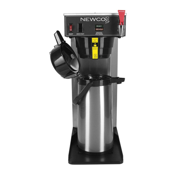
THE ACE SERIES - AUTOMATIC COFFEE EQUIPMENT
Model
Warmers
ACE-S
3
ACE-LP
3
ACE-AP
0
ACE-D
0
ACE-TC
0
ACE-LD
0
ACE-TS
0
Newco Enterprises, Inc. * 3650 New Town Blvd * St. Charles, MO 63301 * Ph 800.325.7867 * Fax 636.925.0029
Width
Depth
Height
8-1/2
16-1/2
17-7/16
15-1/2
16-1/2
15-7/8
8-1/2
17-11/16
22-1/4
8-1/2
17-11/16
26-1/4
8-1/2
17-11/16 16-9/16
8-1/2
17-11/16
20-1/8
8-1/2
17-11/16
Varies
120 V Watts
Weight
US
Canada
29
1710
1410
31
1710
1410
29
1760
1410
32
1760
1410
28
1760
1410
28
1760
1410
34
1760
1410
Man PN 102863
Rev 20170209
120 V Amps
240 V
US
Canada Watts Amps
14.3
11.8
3810
14.3
11.8
3810
14.7
11.8
3510
14.7
11.8
3510
14.7
11.8
3510
14.7
11.8
3510
14.7
11.8
N/A
17.2
17.2
14.6
14.6
14.6
14.6
N/A

Advertisement

Table of Contents
loading

Summary of Contents for Newco ACE-S

  • Page 1 11.8 3510 14.6 ACE-LD 8-1/2 17-11/16 20-1/8 1760 1410 14.7 11.8 3510 14.6 ACE-TS 8-1/2 17-11/16 Varies 1760 1410 14.7 11.8 Newco Enterprises, Inc. * 3650 New Town Blvd * St. Charles, MO 63301 * Ph 800.325.7867 * Fax 636.925.0029...
  • Page 2 ACE CONTROL OVERVIEW The ace series brewers have been upgraded to include the “Super Ace” control. This control has all the features of the previous Ace control board with the additional options of pulse brewing, auto arm and half/full brew in one new compact control.
  • Page 3: Plumber's Installation Instructions

    PLUMBER'S INSTALLATION INSTRUCTIONS CAUTION: Power to brewer must be OFF before proceeding with plumbing installation. 1. Flush water line before installing brewer. Brewer should be connected to COLD WATER LINE only. 2. Water pressure should be at least 20 lbs. For less than a 25 ft run, use 1/4" copper tubing and connect to 1/2" or larger water line.
  • Page 4: Coffee Preparation Procedures

    COFFEE PREPARATION PROCEDURES 1. Place filter into brew basket. 2. Put the proper amount of coffee into the filter. 3. Slide the brew basket into holder. 4. Place the appropriate empty decanter into position below the brew basket. For airpots first open lid and remove pump stem.
  • Page 5: Warranty

    NEWCO’S SOLE OPTION AS SPECIFIED HEREIN, TO REPAIR, REPLACEMENT OR REFUND. In no event shall Newco be liable for any other damage or loss, including, but not limited to, lost profits, lost sales, loss of use of equipment, claims of Buyer’s customers, cost of capital, cost of down time, cost of substitute equipment, facilities or services, or any other special, incidental or consequential damages.
  • Page 6: Troubleshooting Guide

    TROUBLE SHOOTING GUIDE SYMPTOM POSSIBLE CAUSE WHAT TO CHECK REMEDY CAN'T START BREW CYCLE 1. No water. 1. Incoming water lines and water 1. Be sure water shutoff valve is open. shutoff valve. 2. No power. 2. Fuse or circuit breaker. Power 2.
  • Page 7 TROUBLE SHOOTING GUIDE SYMPTOM POSSIBLE CAUSE WHAT TO CHECK REMEDY IRREGULAR YIELD 1. Not siphoning properly. 1. Refer to "DRIPPING" Step 1. 1. Refer to "DRIPPING" Step 1. 2. Control board/timer. 2. Timer consistency. Time several 2. If times are irregular replace board. brew cycles.
  • Page 8 ACE SERIES BREWERS – REPLACEMENT PARTS LIST ELECTRICAL COMPONENTS TANK AND PLUMBING Part No Description Part No Description 100010 Warming plate ass'y 120 V, black 102798 Tank ass'y, 120 V 1400 W 100187 Warming Element, 120 V 100 W 102859 Tank ass'y, 120 V 1750 W 102581 Element main heating, 1100 W 120 V...
  • Page 9 T a b l e 1 - T i m e r S e t t i n g R e q u i r e d T o O b t a i n D e s i r e d V o l u m e Desired F l o w R a t e –...
  • Page 10 Telescoping Brewer Supplemental Information Telescoping Brewer Principal of Operation - Your brewer is equipped with a telescoping column to allow periodic adjustment of the brewer height. This feature allows continued use of the same piece of brewing equipment although the dispensers may change over time. The brewer has an inner and an outer column which slide up and down against each other.
  • Page 11 Telescoping Brewer Chasis Diagrams Telescoping Brewer 120 V Wiring Diagram PAGE 11...
  • Page 12: Wiring Diagrams

    WIRING DIAGRAMS PAGE 12...
  • Page 13 Wiring Continued - Thermal Brewer Shown With Autoarm 240V 120V Miscellaneous Figures Valve Section View Micro Switch Section View PAGE 13...

This manual is also suitable for:

Ace-lpAce-dAce-apAce-tcAce-tsAce-ld

Table of Contents