
Related Manuals for Oldham MX 32


Summary of Contents for Oldham MX 32
- Page 1 Installation and MX 32 Operating Manual 2 CHANNEL CONTROLLER SINGLE CHANNEL Reference: NPM32GB Revision: B.1 The Fixed Gas Detection Experts...
- Page 2 Copyright 2013 by Oldham All rights reserved. Reproduction in any form, in whole or in part, without the express written consent of Oldham is strictly prohibited. The information contained within this manual is true and correct to the best of our knowledge.
-
Page 3: Table Of Contents
Cal Menu (Calibration) ................25 Cod Menu (Access code) ................30 Buz Menu (Buzzer) ..................31 │Cleaning, servicing and maintenance ..... 33 Chapter 5 Cleaning ....................33 Maintenance and servicing ................ 33 Fuse replacement ..................34 MX 32 Instruction Manual... - Page 4 │ Particular Specifications ......... 39 Chapter 8 Specifications for mechanical and electrical installations in Explosive Zones........... 39 Metrological specifications ................. 39 Connecting detectors other than Oldham detectors to the MX 32 controller ..........40 Markings: ....................41 MX 32 Instruction Manual...
-
Page 5: Chapter 1 │General Information
On behalf of its clients, Oldham reserves the right to modify the technical characteristics of its equipment, without notice, to improve product performance. This user manual and its contents are the inalienable property of Oldham. -
Page 6: Safety Warnings
Oldham had been informed of such damages. -
Page 7: Chapter 2 │General Introduction
│General Introduction Chapter 2 Subject The MX 32 controller is intended for light units that do not require an electrical cabinet. The MX 32 measurement and alarm controller can measure 1 or 2 channels independently. Each channel is linked to one or more sensors installed in the locations being monitored. -
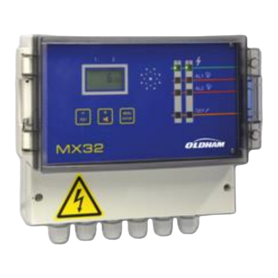
Page 8: View: Front
View: Front Figure 2: Full view of the MX 32 controller. Ref. Function Button to increase the value displayed or flip to the next menu/option. Button to decrease the value displayed or flip to the previous menu/option. LCD screen displaying measurements, menus and options. -
Page 9: Lcd Information
LCD Information Figure 3: LCD Information. Ref. Function See page Indicator for alarm threshold rising. Indicator that Channel 1 is selected. See Figure 2, ref. D. Digital indicator (measurement value, alarm threshold value, etc.) Indicator that Channel 2 is selected. See Figure 2, ref. D. Percent symbol. - Page 10 F13 Fuse (5x20, 250 V AC – 630 mA T). F11 Fuse (5x20, 250 V AC – 630 mA T). alarm relays are configured as energized at the factory. This means that they are supplied with power when not in alarm. MX 32 Instruction Manual...
-
Page 11: Chapter 3 │ Installation And Wiring
│ Installation and wiring Chapter 3 Mounting the controller The MX 32 controller can be installed in any location except for explosive atmospheres. Ideally, the controller should be located in an area under surveillance (security office, control room, equipment room , etc.). -
Page 12: Wiring
The cable used must have a minimum diameter of 1.5 mm² and a maximum diameter of 2.5 mm². Refer to the wiring examples beginning on page 11. Power The MX 32 must be protected upstream by a differential bipolar circuit breaker. The response curve must be type D. Power supply 115 V AC... - Page 13 11. Protection is provided by fuse F7 (2A/250 VAC) (Figure 4, ref. B). Measurement Channels The MX 32 controller can be equipped with one or two adjustable and dual measurement channels (see Figure 7). Three options are suggested at purchase: ■...
- Page 14 (Figure 4, ref. S and T). Alarm relays The MX 32 controller uses two alarm relays per measurement channel which correspond to two instant pre-programmed alarm thresholds 1 and 2.The relays are energized (de-energized available on request) and voltage-free.
- Page 15 *Capacity to cut the power to relays 120 VA- 30W resistive; use a relay with external power source if necessary. Figure 8: MX 32 controller with 1 explosive sensor on Channel 1 and dual explosive sensors on Channel 2. 3 – Installation and wiring...
- Page 16 30W resistive; use a relay with external power source if necessary. Shared fault indicator Figure 9: MX 32 controller with 1 explosive sensor on Channel 1 and 2 parking CO sensors on Channel 2 (maximum of 5 loop-connected sensors). MX 32...
-
Page 17: Chapter 4 │Operating Instructions
│Operating instructions Chapter 4 Displays Indications for start-up Action or result Illustration ■ Current version of the software and buzzer test. ■ Access code for menus currently programmed. ■ Display of current AL1 threshold for channel #1. Simultaneously, the AL1 and Fault-channel 1 indicators light up. - Page 18 Display of the measurement for the channel selected..or. ■ One minute later, if the (-) or (+) buttons are not pressed, the display will return to cyclic display of the two measurement channels (if in use). MX 32 Instruction Manual...
- Page 19 Press (-) AND (+) together. ■ The measurements disappear and are replaced by dashes. The MX 32 controller continues to monitor the sensor(s) but the display is hidden. No display of measurements after cyclic display Action or result Illustration ■...
-
Page 20: Navigating The Menus
■ The measurements disappear and are replaced by dashes. The MX 32 controller continues to monitor the sensor(s) but the display is hidden. Navigating the menus Reminder: for security reasons, only trained personnel (with access codes) are authorized to use the menus listed below. - Page 21 ■ Press (+) to display the INI menu (Initialization/Start-up). See page 25 for instructions on using this menu. ■ Press (+) to display the COD menu (Access Code). See page 30 for instructions on using this menu. ■ Press (+) to display the BUZ menu (Buzzer). See page 31 for instructions on using this menu.
-
Page 22: Prg Menu (Programming)
The alarm relays for the channel are blocked. Start-up or stopping the channel ■ Activating or deactivating the channel: (-) deactivates the channel (channel stopped). (+) activates the channel (channel in operation). ■ Confirm by pressing MENU/ENTER MX 32 Instruction Manual... - Page 23 Selecting the gas to be detected ■ Press (-) to display a list of the gases programmed. Then use to display the other gases again. ■ Confirm by pressing MENU/ENTER Selecting the unit of measurement ■ Press (-) or (+) to display a list of the units programmed (%, LIE, PPM, PPB, UEG, C, BAR, MG, ----).
- Page 24 (+) to define each of the 4 digits for the time delay (in minutes, seconds). Confirm the 4 digits by pressing MENU/ENTER Example: the value 10.20 indicates a time delay at start-up of 10 minutes and 20 seconds. MX 32 Instruction Manual...
- Page 25 (-) or (+) to define the operating mode for the yellow sensor LED: MAN: no visualization (blinking yellow LED) by the MX 32 controller, of the sensor being calibrated (sensor maintenance mode). OTH: visualization (blinking yellow LED) on the controller when the sensor is being calibrated.
- Page 26 Return to measurement display ■ Indicating the current measurement. If necessary, repeat the same procedure for the other channel. MX 32 Instruction Manual...
-
Page 27: Ini Menu (Initialization)
This menu is used to automatically initialize the measurement curve managed by the microprocessor with the sensor connected to the appropriate channel. It is used in the following situations: ■ By Oldham when shipping new material. ■ At the initial installation. ■... - Page 28 Return to normal measurement display ■ The screen will display the current measurement. Important: once the settings are completed, perform a new calibration for this measurement channel; see the following paragraph. MX 32 Instruction Manual...
-
Page 29: Cal Menu (Calibration)
The only way to verify the accuracy of the detection function of the sensor(s) linked to the MX 32 controller is through calibration using a test gas. Gas detectors are safety devices. Accordingly, Oldham recommends regular testing of fixed gas detection installations. This type of test consists of injecting a standard gas of sufficient concentration into the sensor to set off the pre-adjusted alarms. - Page 30 If the display is not zero, adjust the zero measurement by moving the zero potentiometer corresponding to the appropriate channel (Figure 4, ref. R for Channel 1 or ref. O for Channel 2). ■ Confirm the zero by pressing ENTER MX 32 Instruction Manual...
- Page 31 Sensitivity settings ■ Inject the calibration gas (60 l/h) at sensor level and wait for signal stabilization. ■ Confirm the entry in the sensitivity settings by pressing ENTER Display of the current value. = setting the. icon is displayed. The yellow indicator of the corresponding channel blinks (the channel relays are blocked).
- Page 32 The yellow indicator of the corresponding channel blinks (the channel relays are blocked). If necessary (displayed value other than the value of the calibration gas), adjust the sensitivity by using the (+) or (-) buttons. MX 32 Instruction Manual...
- Page 33 ■ Confirm the sensitivity by pressing ENTER Caution: never confirm without having injected gas and completed the settings, at the risk of false triggering. Saving calibration ■ Press: (+) to select Yes. The completed calibration will be saved. (-) to select No. The changes will be abandoned and the old calibration will be saved.
-
Page 34: Cod Menu (Access Code)
(+) to select Yes. The new code will be saved. (-) to select No. The changes will be abandoned and the old code will be saved. ■ Confirm by pressing MENU/ENTER Return to measurement display ■ The screen will display the current measurement. MX 32 Instruction Manual... -
Page 35: Buz Menu (Buzzer)
Buz Menu (Buzzer) Action or result Illustration ■ indicator blinks. ■ Press ) to confirm. ENTER Defining the buzzer action ■ The ON or OFF icon blinks, depending on the current buzzer configuration. ■ Select On or Off: On: the buzzer will be activated in the case of alarm or a fault. - Page 36 MX 32 Instruction Manual...
-
Page 37: Chapter 5 │Cleaning, Servicing And Maintenance
│Cleaning, servicing and Chapter 5 maintenance Cleaning Do not use alcohol- or ammonia-based liquids to clean the central controller. If necessary, clean the exterior of the enclosure with a damp cloth. Maintenance and servicing The controller does not require special servicing. Adjustments Caution: the settings operations in this paragraph are reserved for authorized, trained personnel because they may compromise... -
Page 38: Fuse Replacement
However, it should not be greater than one year. Safety Procedures The site manager is responsible for implementing the safety procedures on his site. Oldham is not responsible for implementing safety procedures. ■ Refer to the Menu Initialization paragraphs (page 23). ■... -
Page 39: Chapter 6 │Technical Specifications
│Technical specifications Chapter 6 6 – Declaration of Conformity... - Page 40 MX 32 Instruction Manual...
-
Page 41: Chapter 7 │Technical Specifications
│Technical specifications Chapter 7 Case Enclosure: wall-mount. Dimensions: 240 x 205 x 120 mm. Material: ABS plastic Cable input/outputs: 6 x PG9 type cable glands. Protection: IP65. Power supply Power supply: ■ 115 or 230 VAC. ■ 21 V to 30 V DC. Power consumption: 30 VA. - Page 42 (3) G for metrology in the detection of ATEX Directive 94/9/EC: explosive gases EN 61779-1 and 4 in Zone 2. Low Voltage Directive: in compliance with EN 61010-1:10. Electromagnetic Compatibility (EMC) in compliance with EN 50270:06. Directive: MX 32 Instruction Manual...
-
Page 43: Chapter 8 │ Particular Specifications
All installations must be in compliance with currently enforced standards, notably standards EN 60079-14, EN 60079-17, and EN 50281-1-2. The MX 32 controller must not be subject to intense mechanical vibration and must be installed in a safe area away from explosive atmospheres. -
Page 44: Connecting Detectors Other Than Oldham Detectors To The Mx 32 Controller
In the case that the user connects a non - Oldham brand detector to the MX 32 controller, the user must ensure that the transfer curve is compatible with the input characteristics for the controller, so that the information delivered by the detector will be properly interpreted. -
Page 45: Markings
In the case that the user connects a non - Oldham brand detector to the MX 32 controller, the user must ensure that the transfer curve is compatible with the input characteristics for the controller, so that the information delivered by the detector will be properly interpreted. - Page 46 MX 32 Instruction Manual...
- Page 48 The Fixed Gas Detection Experts EUROPEAN PLANT AND OFFICES Z.I. Est – rue Orfila CS 20417 – 62027 ARRAS Cedex FRANCE Phone: +33 (0)3 21 60 80 80 – Fax: +33 (0)3 21 60 80 00 Web site: http://www.oldhamgas.com AMERICAS ASIA PACIFIC EUROPE Phone: +1-713-559-9280...
Need help?
Do you have a question about the MX 32 and is the answer not in the manual?
Questions and answers