
Subscribe to Our Youtube Channel
Related Manuals for Oldham MX 32


Summary of Contents for Oldham MX 32
- Page 1 MX 32 User Manual Analog and Digital Controller Part Number: NP32V2EN Revision: C.0 The Fixed Gas Detection Experts...
- Page 2 Copyright January 2018 by Oldham S.A.S. All rights reserved. The reproduction of all or any section of this document in any form whatsoever without the written permission of Oldham S.A.S. is forbidden. The information contained in this manual is accurate to our knowledge.
-
Page 3: Table Of Contents
Important Information ..................2 Liability Limits ....................2 Warranty ......................2 Chapter 2 │General Introduction ............3 Purpose of the MX 32 controller ..............3 The different Versions ..................5 Firmplate ......................6 The COM 32 Software ..................6 Chapter 3 Mechanical Installation ............ 7 MX 32 Controller ..................... - Page 4 Reliability data ....................63 Specific Conditions of Use ................63 Specific instructions for the prevention of explosions according to ATEX 2014/34/EU European Directive ..............64 Connecting detectors other than Oldham detectors to the MX 32 controller . 65 MX 32 User Manual...
-
Page 5: Chapter 1 │General Information
The aim of this manual is to supply simple and accurate information to the user. Oldham cannot be held liable for any misinterpretations in the reading of this manual. In spite of our efforts to produce an error-free manual, it may nonetheless contain some unintentional technical inaccuracies. -
Page 6: Safety Instructions
Neither Oldham nor any other associated company under any circumstances can be held liable for any damage, including, without limitations, damages for loss or interruption of manufacture, loss of information, defect of the MX 32 controller, injuries, loss of time, financial or material loss, or any direct or... -
Page 7: Chapter 2 │General Introduction
LED indicators go off. At the same time, the corresponding relays are activated to drive the additional actions programmed by the user. The MX 32 controller is programmed by using the COM 32 configuration software. Figure 2 presents a configuration example. - Page 8 Logic Input Module 16 logic inputs Four 4-20mA Analog Output Module 8 Analog Input Module Analog inputs Analog recorders Figure 2: Example of an MX 32 configuration using different analog and digital detectors as well as digital modules MX 32 User Manual...
-
Page 9: The Different Versions
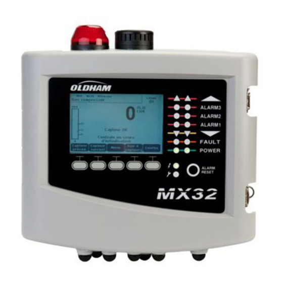
The different Versions The MX 32 controller is available in 3 versions: ■ 1 line, ■ 2 lines, ■ Bridge Version (2 channels) for direct monitoring of Wheatstone bridge flammable gas detectors. Figure 3: MX 32 The following table details the different possible configurations depending on the controller’s version. -
Page 10: Firmplate
Serial Number. The first two digits (in this case 17) correspond to the year of manufacture (in this case 2017). Variant (1 or 2 lines to work with 4-20mA analog detector or Oldham digital detector, or 2 channels to work with Wheatstone bridge gas detectors). In this example, version ‘Wheatstone Bridge’. -
Page 11: Chapter 3 Mechanical Installation
Access to the controller must be ensured in order to facilitate adjustments, monitoring, and cabling. A space of 400 mm is necessary in front of the MX 32 for opening the door. Use 3 fixing screws 4x25 mm for fixing the case support. -
Page 12: Gas Detectors
Heavy gases are detected close to the ground, while lighter gases are present along the ceiling. If necessary, contact Oldham for any questions regarding proper detector positioning. -
Page 13: Chapter 4 │The Mx 32 Controller
Zone 1 status indicator Power On/Off indicator Zone 2 status indicator Failure/maintenance indicator Integrated siren (option) Contextual soft keys Integrated flash (optional) Alarm Acknowledgement button Figure 7: External view of the wall-mounted and rack-mounted versions 4 – The MX 32 Controller... - Page 14 2. MX 32 firmware update via a PC Once the unit configuration or update is complete, always set back the selector in the "0" position. The MX 32 will resume automatically. Microcontroller reset button. Press this button to reset the controller.
- Page 15 On-board additional siren, settable from 85 to 100dB (option) CR2032 lithium battery. Allows data and real time clock saving in case of power failure. Runtime is approx. 450 days while power off. Keep the MX 32 powered during battery replacement.
-
Page 16: Front Plate
Faut relay terminal. DPCO relay, 250Vac-30Vdc / 5A Front Plate Figure 9: MX 32’s front plate LCD (A) The display shows the measurements or the settings menus. When an alarm occurs, the display turns in grayscale mode to indicate the channel that is currently displayed is on alarm. - Page 17 - Blinking: at least one gas detector of the corresponding zone is in alarm condition. Acknowledgment is programmed in manual mode and has not been required yet. 4 – The MX 32 Controller...
- Page 18 Figure 9: MX 32’s front plateD) Available as an option, blue or red, is configurable via COM 32. Status indicators (F and G) These two indicators reflect the status of the MX 32. Icon Function Green indicator denoting the power supply status...
-
Page 19: Alarm Thresholds And Relays
( Figure 9: MX 32’s front platetags D and E) are configured though COM 32 application. Note: It is possible to modify a programmed alarm level via the MX 32’s user interface (Program menu). Internal Relays and Buzzer ■... -
Page 20: Firmplate
Table 3: Alarms in Manual Acknowledgement mode Firmplate Firmplates are attached on the right side, on the top and behing the front cover of the MX 32. Following information can be found: ■ Model (1 or 2 lines and power supply type) ■... -
Page 21: Chapter 5 │Digital Modules
Up to 5 modules can be used with the single line version and up to 10 modules can be used with the 2 line models. The MX 32 in bridge version is not compatible with any modules (see Table 1:). The following table lists the... -
Page 22: Rs485 Transmission
+ 24Vdc, 0V, A, B terminals are respectively connected to +24Vdc, 0V, A, B terminals of the other modules and then to the terminal of the corresponding line on the controller. The cable shield must be connected to the MX 32 ground terminal. - Page 23 DIP switches DIP switches (ON = 1; OFF = 0) (ON = 1; OFF = 0) Table 5: Addressing table (address depends on the position of the switches) Remarks: ■ The physical address of a module (1 to 32 max) must be identical to the registered address via COM 32 software configuration.
-
Page 24: Relay Modules
Each switch drives the relay having the same number (switch #1 acts on relay #1). The contacts are represented with the module not powered. Re the 4 relay module, only switches #1 to #4 are active. MX 32 User Manual... - Page 25 E – Programmable relays The 2 line MX 32 model can manage up to 16 external relays (limited to 4 relay output modules). The relays are individually programmable. The operation of each relay depends on its configuration. Each detector event [AL1 - AL2 - AL3 – OVS – UDS – Failure] can control one or several relays.
-
Page 26: 16-Logic Input Module
Factory settings. Do not modify Remplissage de trame Delay Factory settings. Do not modify Temporisation E.O.L Resistor See details in paragraph End of line Resistor, on page 19 Résistance F.D.L. Table 7: Configuration DIP switches of the Logic Input Module MX 32 User Manual... -
Page 27: 8-Analog Input Module
C – Logic input connectors Each of these 16 inputs can be connected to a voltage-free contact as per Figure 30. Input status is transmitted by the digital line to the MX 32. There is no alarm when the contact is closed. - Page 28 19). If the value measured is different from 1.6 V, adjust B. Should the adjustment value be different, calculate: V= I (mA) x 0.10 (V/mA) Example: If the current is 12 mA, “V” must be equal to 0.8 V MX 32 User Manual...
-
Page 29: 4-Analog Output Module
4-Analog Output Module Function This digital module delivers 1 to 4 2 logic inputs discrete opto-isolated analog outputs deactivated. Several detectors can be assigned to one output allowing the management of the lowest, highest and averaged value. When non configured, the analog output is set to 0mA. - Page 30 MX 32 User Manual...
-
Page 31: Chapter 6 │Wiring And Electrical Connections
100-240Vac Power Supply The MX 32 can be powered from a 100-240Vac source at 50/60 Hz, 1.5A max. Check the nature of the current and the voltage value prior to any connection. The electrical connections must be carried when power is down. - Page 32 Figure 23: Connection of 24Vdc external power supply (A) Grounding The MX 32 meets EMC and Low Voltage Directives requirements. In order to fully comply with the class of protection, it is absolutely necessary to connect the ground terminal to the Earth of the site (Figure 24, A). Moreover, the cable braids of the digital and analog lines shall also be connected to this ground terminal.
- Page 33 Power (24Vdc) Figure 25: 4-20mA detector connected to an analog line In the case of a mV flammable gas detector connected directly to the MX 32 line, please wire the detector as shown below. Figure 26: connection of a Wheatstone type gas detector to a Wheatstone type MX 32...
-
Page 34: 4- Or 8-Relay Modules
Figure 28: Remote acknowledgement connection (A). 4- or 8-Relay Modules Supervised contact Supervised contact To MX 32 4 or 8 output contacts DPCO To next module or previous module (2A/250Vac-24Vdc Figure 29: 4- or 8-relay module connections If this module is the last on the line, do not forget to set the switch marked EOL resistor/resistance FDL to ON. -
Page 35: 16-Logic Input Module
16-Logic Input Module Supervised contact Supervised contacts To MX 32 To next module or previous module Figure 30: 16-logic input module connections. If this module is the last on the line, do not forget to set the switch marked EOL resistor/resistance FDL to ON. -
Page 36: Analog Output Module
Output Output 4-20 mA n°2 4-20 mA n°4 To MX 32 To the next module or the previous module Figure 33: 4-analog output module connections. If this module is the last of the line, do not forget to set the switch marked EOL Resistor/FDL resistance to the ON position. -
Page 37: Chapter 7 │Menus
↓ ↓ 4 MAINTENANCE 5 INFORMATION See page 40 See page 41 Figure 34: General menu tree of the MX 32 Navigation Key Functions Function Vertical displacement in the selected menu block. Horizontal displacement between two menu blocks. -
Page 38: Display In Normal Mode
The vertical dotted line displays the concentration and time stamp of the point being considered. Escape: return to display of values. Information on the detector status. Information on the MX 32 status. MX 32 User Manual... -
Page 39: Main Menu
Zone of indication of activated alarms with blinking threshold display. The screen changes to inverse video (Figure 35). Figure 36: Example of a curve display screen Main Menu This displays all the management menus of MX 32. Figure 37: Main menu 1. System ■... -
Page 40: Program
Screen saver ■ OFF: no screen saver. ■ ON: turns into the screen saver mode (displays Oldham logo) if no key is pressed for a certain period of time. Averaged value ■ OFF: averaged gas measurement value is not displayed. - Page 41 ↑↓ keys. Validate by pressing Enter. Note: Only analog detectors that are not equipped with a local display can be calibrated from the MX 32 controller. For the other detectors, the menu “Sel. Detector” only makes it possible to put them in calibration mode so that they do not activate alarms during their manual calibration.
- Page 42 3. Confirm the sensitivity calibration by pressing Validate Sens. Record the calibration 1. The message “Do you want to validate zero and detector sensitivity?” is displayed. Press Validate calibration to confirm the adjustment of zero MX 32 User Manual...
- Page 43 2. Proceed with the cell replacement and then calibrate locally the corresponding detectors 3. Proceed with the calibration from the MX 32 via the menus “1 Sel detectors”, “2 recording”, "End recording” and “4 validation” in order to save data calibration (wear rate, date of calibration, response time, etc.).
-
Page 44: Maintenance
The events log indicates Begin Simulation and End Simulation. ■ Exit the simulation mode by pressing the End simul key. Automatic release then occurs and resets the average values to zero. The current measurements are displayed once more. MX 32 User Manual... -
Page 45: Information
Al2, Al3, Al1mean, Al2mean, Al3mean, OVS), status (activated = ON or deactivated = OFF) as well as the date and time of occurrence or of the release. The letter “S” appears on the line if the events were obtained when the MX 32 was in simulation mode Delete deletes all the data. - Page 46 Table 13: Relay and logic input file messages. 4. Working conditions records This displays the actions carried out on the MX 32 (simulation mode, calibration mode, programming mode, release request, operation on internal battery), as well as the date and time of beginning and end of the event.
- Page 47 Significance module absent). MODUL Configuration or module address error. TEMP+ Internal temperature of the MX 32 higher than maximum tolerated value. TEMP- Internal temperature of the MX 32 lower than maximum tolerated value. LINE 1 Incident on line 1 (short-circuit).
- Page 48 MX 32 User Manual...
-
Page 49: Chapter 8 │Main Part Numbers
│Main Part Numbers Chapter 8 MX32-A-B-C-D-E-F-0-1 Stobe and Audible RS 485 serial Version Power supply Language Com 32 software alarm combination output 1 - 1 channel 1 - 24Vdc 1 - French 0 - Without 0 - Without 0 - without 2 - 2 channels 2 - 100/240Vac 2 - English... - Page 50 CR2032 lithium battery 6 111 321 340 mA programming strip (8 maximum per 6 353 442 analog input module), see Figure 19 4-20 mA programming strip (8 maximum per 6 353 443 analog input module), see Figure 19 MX 32 User Manual...
-
Page 51: Chapter 9 │Cleaning And Maintenance
(see Chapter 8 for the list of spare parts). The controller must be first switched off. Power on the controller once the battery has been replaced. Oldham does not allow any other repairs than those listed here above. Burn hazard. As the temperature inside the controller can reach 70°C (158 °F), it should be allowed to cool after aperture. - Page 52 MX 32 User Manual...
-
Page 53: Chapter 10 │Certificate Of Compliance
Chapter 10 │Certificate of Compliance The document hereafter (1 page) reproduces the EC declaration of conformity. 10 – Certificate of Compliance... - Page 54 MX 32 User Manual...
-
Page 55: Chapter 11 │Technical Specifications
Chapter 11 │Technical Specifications MX 32 Controller Function Function Gas Detection Controller Number of lines 1 or 2 as per model Display and indicators Display Back-lit graphic LCD Status indicators - 7 LEDs for each of the 2 lines - 1 Power On/Off visual indicator... - Page 56 = 32W to 25W out-max (max. 0.71A external load for both lines at +40°C) for +40˚C ≤ T ≤ +50˚C, P ■ = 25W to 18W out-max (max. 0.42A external load for both lines at +50°C) MX 32 User Manual...
-
Page 57: Relay Module
Terminals Screw terminals. Can accept 2.5 mm² (14AWG) wire Relay Module Function Function Management of 4 or 8 relays from the digital signals issued by the MX 32 Number of relays ■ 4 or 8 relays ■ DPCO contact relays Relay type ■... -
Page 58: 8-Analog Input Module
< 5 mA with the 4 lines at stop ■ < 36 mA for an activated line ■ < 130 mA for the 4 activated lines Assembly DIN rail mounted Dimensions 125 x 165 x 60 mm MX 32 User Manual... -
Page 59: Chapter 12 | Rs485 Digital Output
Chapter 12 | RS485 Digital Output The MX 32 units using the RS485 Modbus option are equipped with a communication card (code 6451680), which is affixed to the motherboard. This card generates a RS485 output in Modbus RTU format. Card description Figure 41: RS485 card Rep. -
Page 60: Transfer Table
Access to measurements from the sensor located at line 2 and address 32 of unit n° 2. A. Determination of the sensor address: (2 – 1) x 32 + 32 = 64 B. Structure of the Modbus request: MX 32 User Manual... -
Page 61: Address Table
01 = 0x0001 Thread: 0x01 0x03 0x09 0xFD 0x00 0x01 0xCRC 0xCRC Address Table Supervision of the MX 32 sensors All reading requests for the Modbus are done via function 3. The cartography is shown below: From addresses 0 to 1999, the Modbus... - Page 62 Configuring sensors Downloading the configuration The MX 32 uses 64 external addresses (line #1 channel #1, to line #2 channel #32) and 2 analog channels for which the addresses are located from 257 to 258. With the automated system, it is possible to send 66 (64 + 2) Modbus...
- Page 63 Address SENSORS Data type [64 + 2] bytes 1 Com sensor 2 X 16 Unicode text (16 bits) 16 characters including the final /0. 17 Status Start / Stop: if in operation, variable = 1. If stopped, variable = 0. 18 Gas name 2 x 20 Unicode text (16 bits) 20...
- Page 64 + measurement < alarm. 68 Increasing or Configuration per bit Al 1, 2, 3 instantaneous or decreasing average increasing or alarm? decreasing 1: increasing 0: decreasing Table of registers (below) MX 32 User Manual...
- Page 65 Acquisitions retrieved cyclically Real address SENSOR Data type MEASUREMENTS bytes [256 + 8] If digital Sensor measurement Table with 66 signed integer of 16 bits where the measurements are Start: 2001 listed at their address. The end : 2064 measurement being whole, the If analog automatic system uses the Display Start: 2257...
- Page 66 MX 32 User Manual...
-
Page 67: Chapter 13 │ Specific Conditions Of Use And Functional Safety
SIL 1 certification is pending and scheduled by July 2018. Specific Conditions of Use The safety function of the MX 32 is the processing of the signal of the detectors linked to its input. As soon as a measurement reaches a programmed threshold, an audio and visual alarm goes off. -
Page 68: Specific Instructions For The Prevention Of Explosions According To Atex 2014/34/Eu European Directive
(gas detectors and controllers). As such, MX 32 controller is certified as a safety device and can be used in systems that contribute to reduce the risk of explosion. The information described below must be taken into account and fulfilled by the site manager. -
Page 69: Connecting Detectors Other Than Oldham Detectors To The Mx 32 Controller
The following table shows the controller status depending on the detector analog signal output. In the event the user connects a non-Oldham brand detector to the MX 32 controller, the user must ensure that the detector is compatible with the input characteristics of the controller, so that the information delivered by the detector will be properly interpreted. - Page 70 MX 32 User Manual...
- Page 71 13 – Functionnal Safety...
- Page 72 The Fixed Gas Detection Experts EUROPEAN PLANT AND OFFICES Z.I. Est – rue Orfila CS 20417 – 62027 Arras Cedex FRANCE Tél: +33 (0)3 21 60 80 80 – Fax: +33 (0)3 21 60 80 00 Website: https://gasdetection.3M.com AMERICAS ASIA PACIFIC EUROPE Tel: +1-713-559-9280 Tel: +86-21-3127-6373...
Need help?
Do you have a question about the MX 32 and is the answer not in the manual?
Questions and answers