Advertisement
Quick Links
Installation and Operating Instructions
WARNING: Elderly persons, pregnant women, or those suffering from heart disease, high blood
!
pressure, diabetes, or who are otherwise not in good health, do not use this device unless directed
to do so by a physician. Also, do not use steambath while under the influence of alcohol.
IMPORTANT: the TC-135 Control will only function with one of the following Steamist Generator models: SM-46,
SM-79, SM-4, SM-5, SM-7, SM-8, SM-11, SM-12, SM-15, System-18, System-24, System-30.
IMPORTANT: This control must be installed inside the
steam room for proper operation of the system.
3
5
SET
TEMP
6
Digital Temperature Control
Cleaning Instructions: Use a damp cloth and mild soap.
Do NOT use abrasive cleaners which might scratch the
surface or the base of the control.
1. Pre-Installation - Control Location
a)
The TC-135 control must be installed inside the
steam room.
For convenience the recommended
height from the floor is four feet. Provide a 1½" hole in
the wall at this location (see Figure 1).
IMPORTANT:
Multi-conductor
installed so that the end will not be buried inside the
wall. The unit will not operate unless the control is
2. Electrical Rough-in
a)
Remove the multi-conductor cable from the control
packing box. Carefully route the multi-conductor
control cable from the Steambath Generator to the
TC-135 located inside the steamroom (see Figure 2).
Route multi-conductor cable though a ¾" conduit to
protect the cable from damage and to facilitate
replacement if necessary.
06/07
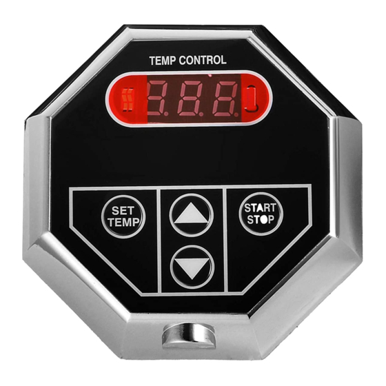
Control Features
TEMP CONTROL
START
STOP
TC-135
Installation Instructions
cable
must
1.
Temperature Display: Indicates steam room or set
point temperature.
2.
Start/Stop Key Pad: Press key pad and generator will
begin producing steam in a few minutes. The generator
1
will remain on for 30 minutes when used with the
models SM-46, SM-79, SM-4, SM-5, SM-7, or SM-8
steam generators and 60 minutes for larger generators.
Pressing the key pad a second time will stop the Steam
Generator.
4
3.
Heat Icon: Indicates the generator is producing steam
when illuminated. The heater in the generator and the
heat icon will cycle on and off as the temperature is
maintained automatically in the steam room.
4.
Temperature icon: Indicates the set temperature has
2
been reached and the heater in the generator is off.
This icon will cycle on and off opposite that of the heat
icon.
5.
Set Temperature Key Pad: Press to display the set
point.
6.
Up/Down Key Pads: Press to adjust the temperature
set point.
IMPORTANT: Run the
Control Cable through
a ¾" conduit.
be
1½" Hole
located four feet
from the floor
- 1 -
Steambath Control
Model: TC-135
Figure 1
TC-135 Digital
Temperature Control
Double-sided
Adhesive Pad
Pub. No. 554- E
C
US
®
LISTED 995C
Coupler
Advertisement

Related Manuals for Steamist TC-135


Summary of Contents for Steamist TC-135
-
Page 1: Installation Instructions
Also, do not use steambath while under the influence of alcohol. IMPORTANT: the TC-135 Control will only function with one of the following Steamist Generator models: SM-46, SM-79, SM-4, SM-5, SM-7, SM-8, SM-11, SM-12, SM-15, System-18, System-24, System-30. - Page 2 IMPORTANT: The adhesive on the back of the continuing on to the next step. TC-135 control will NOT seal this control. It is the responsibility of the installer to seal this control to the wall with the supplied silicone. Water damage to the ¾“...
- Page 3 WARNING: When installing a steam pipe into a steam Start-up and test the Steam Generator and Control. room made out of Acrylic, Cultured Marble, Corian, IMPORTANT: The Steam Generator will NOT operate Swanstone, Resin, Plastic or an equivalent type of material, without water.
-
Page 4: Operating Instructions
Installation Suggestions Optional Outside Installation TC-110 Control Steamhead Installation Inside Installation � � Steamhead should be mounted TC-135 Control. Locate away TEMP CONTROL 18” above the finished floor or 6” from the direct line of shower START STOP START TEMP STOP...
Need help?
Do you have a question about the TC-135 and is the answer not in the manual?
Questions and answers