Table of Contents
Advertisement
Quick Links
Download this manual
See also:
Manual
Onboard AC97 CODEC
JP12 Enable/Disable
Onboard Sound
VIDEO-AUDIO-IN Connector
MODEM-CN Connector
CD-IN Connector
Front Panel Audio Connector
AMR Expansion Slot
32-bit PCI Expansion Slot x6
IrDA Connector
WOM Connector
GPO Connector
nd
2
USB Connector
2Mb Flash ROM BIOS
WOL Connector
Dr. LED Connector
Front Panel Connector
Chassis Fan
SPP/EPP/ECP
Parallel Port
PS/2 Mouse
Connector
USB Port
PS/2 Keyboard
COM 1 Port
Connector
MIDI/Game Port
COM 2 Port
MIC-In
Line-In
Speaker Out
ATX Power Connector
Low ESR Capacitor
Resettable Fuse
CPU Fan
FAN1
AGP 4X Expansion Slot
370-pin CPU Socket
with Voltage & Frequency Auto-detection
®
®
supports Intel
Pentium
III and Celeron™
300MHz~1GHz+
VIA Apollo Pro 133A Chipset
supports 100/133MHz FSB
168-pin DIMM Slot x4
supports PC100/PC133 SDRAM
maximum up to 1.5GB
JP14 CMOS Clear Jumper
FDD Connector
ATA/33/66/100 IDE Connector x2
JP23 & JP29 FSB Select Jumper
Advertisement
Table of Contents

Subscribe to Our Youtube Channel
Related Manuals for AOpen AX34 II


Summary of Contents for AOpen AX34 II
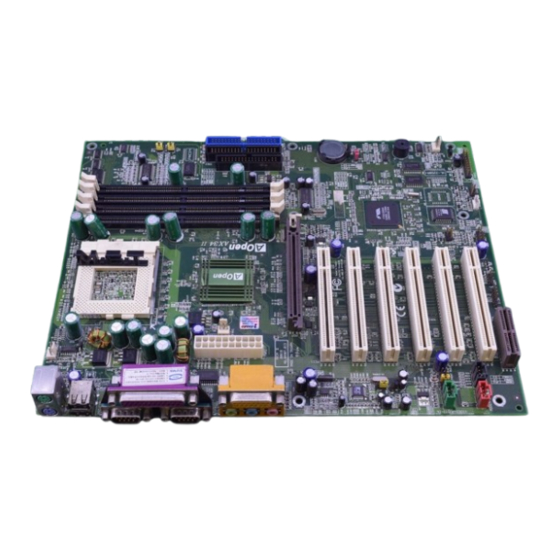
- Page 1 SPP/EPP/ECP Parallel Port PS/2 Mouse MIDI/Game Port Connector USB Port PS/2 Keyboard COM 2 Port COM 1 Port Connector Onboard AC97 CODEC JP12 Enable/Disable MIC-In Onboard Sound Line-In VIDEO-AUDIO-IN Connector Speaker Out MODEM-CN Connector ATX Power Connector Low ESR Capacitor CD-IN Connector Resettable Fuse Front Panel Audio Connector...
-
Page 2: Jp14 Clear Cmos
1. JP14 Clear CMOS You can clear CMOS to restore system default setting. To clear the CMOS, follow the procedure below. 1. Turn off the system and unplug the AC power. 2. Remove ATX power cable from connector PWR2. Everything you need to boot this motherboard is included in this 3. -
Page 3: Installing Cpu
3. Installing CPU 5. Setting CPU Voltage & Frequency Setting CPU Core Voltage CPU Pin 1 and cut edge Pull up the CPU socket level and up to This motherboard supports CPU VID function. The CPU core voltage will be automatically 90-degree angle. -
Page 4: Jp23 Fsb/Pci Clock Ratio
9. Connecting Front Panel Cable This motherboard has four 168-pin DIMM sockets that allow you to install PC100 or PC133 memory up to 2.0GB (or 1.5GB when FSB=133MHz). The AX34 II supports not only SDRAM but also VCM and Registered DRAM. -
Page 5: Front Panel Audio
12. Connecting CD / MODEM / VIDEO-AUDIO-IN Connector 10. Connecting ATX Power Connector VIDEO-AUDIO-IN The ATX power supply uses 20-pin connector shown below. Make sure you plug in the MODEM-CN The CD-IN connector is used to connect CD Audio (Green) (Red) right direction. - Page 6 15. AOpen Bonus Pack CD 17. BIOS Upgrade AOpen Easy Flash is more user-friendly than traditional flash method. The BIOS binary You can use the autorun menu of Bonus CD disc. Choose the utility and driver and select file and flash routine are combined together and you simply run a single file to complete model name.
-
Page 7: Part Number And Serial Number
IDE cable. The problem should be caused by the Check if the system can IDE cables or HDD itself. reboot successfully. Re-install Windows 95, Windows 98 or Windows NT. AX34 II is model name of motherboard; R1.00 is BIOS version... - Page 8 Dear Customer, Test Report: We recommend to choose board/card/device from the Thanks for choosing AOpen products. To provide the best and fastest service to compatibility test reports for assembling your PC. our customer is our first priority. However, we receive numerous emails and http://www.aopen.com.tw/tech/report/default.htm...
Need help?
Do you have a question about the AX34 II and is the answer not in the manual?
Questions and answers