Table of Contents
Advertisement
Advertisement
Table of Contents

Subscribe to Our Youtube Channel
Related Manuals for Bartington Grad601


Summary of Contents for Bartington Grad601
- Page 1 Operation Manual for Grad601 Single Axis Magnetic Field Gradiometer System...
-
Page 3: Table Of Contents
4. Battery Cassette and Charger 4.1. Charging the Battery 4.2. Changing the Battery 4.3. Shipping the Battery 5. Assembly 6. Connections 7. Grad601-2 Carrying Harness 8. Instrument Stands 9. Setting Up 10. Keypad Operation and Display 11. Grid Mode 11.1. Main Menu: Grid Mode 11.2. - Page 4 17.4. Surveying at 2 or 4 lines/m 18. Survey Operation (Grid Mode) 18.1. Interrupting a Survey 19. Downloading Survey Data to a PC 19.1. Installing the Grad601 Datalog Software 19.2. Running the Program 19.3. The Save Screen 19.4. File Formats 20.
- Page 5 BARTINGTON INSTRUMENTS A.4. Grids, Lines and Positions A.5. Survey Methods A.6. Equipment Required A.7. Setting Out the Area A.8. Setting up the Gradiometer A.9. Logging Data A.10. Other Methods Notes Page 5 of 61 OM1800/26...
-
Page 6: List Of Figures
BARTINGTON INSTRUMENTS List of Figures Figure 1: Grad-01-1000L identification label Figure 2: Grad601-2 dual sensor gradiometer arrangement with harness Figure 3: Grad601-1 single sensor gradiometer arrangement Figure 4a: BC601 battery cassette & charger Figure 4b: BC601 battery cassette charging input socket and red LED... -
Page 7: About This Manual
In the following text, references to keys and displayed characters are shown in italic text. The output of the Grad601 represents a differential measurement. As the separation of the sensing elements in each gradient sensor is 1m, all measurements reported in nT also correspond to gradients in units of nT/m. -
Page 8: General Description
BARTINGTON INSTRUMENTS 3. General Description The Grad601 is a single axis, vertical component fluxgate gradiometer comprising a DL601 Data Logger, BC601 Battery Cassette battery cassette, and either one or two Grad-01-1000L cylindrical gradiometer sensors (Figure 1) mounted on a rigid beam. Each sensor contains two fluxgate magnetometers with one metre vertical separation. - Page 9 Figure 3 Grad601-1 single sensor gradiometer arrangement. harness. The Grad601-2, with two sensors, records two lines of data during each traverse and reduces the survey time and distance walked to one half that of using a single sensor gradiometer. Both...
- Page 10 Mode has been added to data loggers with firmware version 7.1 and above, and is purchasable as an upgrade to previous data logger versions if the data logger is returned to Bartington Instruments. In this mode data is not recorded but can be streamed to another device in NMEA format, and is intended to be combined with a suitable GPS device and logger.
-
Page 11: Battery Cassette And Charger
BARTINGTON INSTRUMENTS 4. Battery Cassette and Charger The gradiometer battery is a sealed Lithium Ion type and is housed in a sealed, separate cassette (Figure 4a) which also contains the charging circuitry. 4.1. Charging the Battery To charge the battery, connect the mains adapter supplied, or any isolated 9-18V DC supply (at 1.2A minimum), to the 2.1mm input socket (Figure 4b) for 6-8 hours. -
Page 12: Changing The Battery
BARTINGTON INSTRUMENTS Note: The battery contains electronic protection against short circuit which, if activated, will reset after a delay of 10 minutes. 4.2. Changing the Battery The battery or anti-surge fuse can be replaced by the operator. Remove the back cover of the Battery Cassette. -
Page 13: Shipping The Battery
BARTINGTON INSTRUMENTS 4.3. Shipping the Battery Caution: Batteries and equipment containing batteries should only be shipped in accordance with local regulations. Refer to the IATA website (www.iata.org) for regulations regarding air transport. Caution: If there is any doubt at all as to the integrity of a battery – for example, cracked or dented casing –... -
Page 14: Figure 7A: Dl601 Data Logger Underside
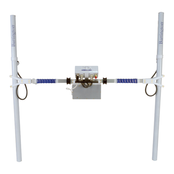
Figure Figure 7a: DL601 Data Logger underside. The Grad601-2 dual sensor gradiometer is carried with the beam across the front of the operator with one sensor on each side as shown in Figure 2. The data logger is located with the controls facing the operator and the battery mounted directly below it, and attached to the data logger through the beam with two knurled captive screws. -
Page 15: Connections
BARTINGTON INSTRUMENTS 6. Connections Figure 7b: DL601 Data Logger connections guide The functions of the sockets on the underside of the data logger are indicated in the label on the front side of the instrument. Caution: Only connect/disconnect the cable from data logger to sensors with the data logger powered off. -
Page 16: Grad601-2 Carrying Harness
Figure 8: Grad601-2 dual sensor gradiometer carrying harness. The harness comprises a lightweight, soft, padded shoulder harness, with a bag to contain a balance weight (sand or water), attached to an abdominal spacer by adjustable webbing straps through two replaceable plastic links. -
Page 17: Setting Up
10. Keypad Operation and Display Figure 9: DL601 Data Logger control panel. The Grad601 Data Logger DL601 (see Figure 9) has 6 keys to set parameters and control the operation. A two-line, 20-character display shows the menus, results etc. The functions of the... -
Page 18: Grid Mode
BARTINGTON INSTRUMENTS Function ON/OFF Controls the power to the unit and sensors. Press to alternately apply and remove power. When the display is blank, the power is OFF. When the display is active, the power is ON. A short delay is incorporated. -
Page 19: Main Menu: Grid Mode
BARTINGTON INSTRUMENTS 11.1. Main Menu: Grid Mode The items in the Grid Mode main menu are as follows: • Start survey • Start scan • Output data • Delete data • Set parameters • Adjust gradiometer • System reset The two-line display will show only two items at a time. The first two items in the Grid Mode main menu will be shown as: >Start survey... -
Page 20: Set Parameters Menu: Grid Mode
BARTINGTON INSTRUMENTS 11.2. Set Parameters Menu: Grid Mode From the main menu select Set parameters and press ENTER. This will give a further menu with default parameters set as shown in the table below. Use the arrow keys to select each item in turn, and then press the STEP key to step through the available options for that parameter. -
Page 21: Nmea Mode
BARTINGTON INSTRUMENTS Threshold Select the deviation in nT at which the alarm is : 1 nT required to operate during a scan operation: increments in units, tens and hundreds and thousands of nT. When the field deviates by the level selected, the... -
Page 22: Set Parameters Menu: Nmea Mode
BARTINGTON INSTRUMENTS The sampling frequency can be changed in the parameters menu, as in NMEA Mode this is not based upon Grid size or walking speed. The ranges and resolution provided in NMEA Mode are the same as in Grid Mode: see Gradiometer Range and Resolution. -
Page 23: Capturing Data In Nmea Mode
BARTINGTON INSTRUMENTS 12.2. Capturing Data in NMEA Mode Whilst in NMEA Mode, the DL601 Data Logger can be connected to any external data logger that is capable of receiving NMEA messages. An NMEA GPS device can then be plugged into the same logger and the data can be correlated. -
Page 24: Operator Magnetic Hygiene
Sensors. 14. Operator Magnetic Hygiene Note: The Grad601 gradiometer is a very sensitive instrument, and any magnetic objects placed near the sensors will affect the measurements. The operator must ensure that there are no magnetic items on their person or in their clothing. -
Page 25: Selecting A Site For Error Measurement And Adjustment
BARTINGTON INSTRUMENTS automatically applies corrections, must be carried out in a previously selected low magnetic gradient area. Note: The setting-up procedure takes only a few minutes. It should be carried out after the instrument has been assembled and left switched on for about 15 minutes. The rotational errors should be checked occasionally, at the original set-up position, and the setting up procedure repeated as necessary. -
Page 26: Adjustment
BARTINGTON INSTRUMENTS easily identified features in the landscape on the north/south and east/west directions from the magnetically clean area selected above. Note: Be sure to remove the compass from the area afterwards or it will interfere with the setup procedure. - Page 27 BARTINGTON INSTRUMENTS the operator should keep the centre of the assembly over a fixed point. This is most easily achieved using the harness. Note: When the display requests that the sensors be moved to the opposite direction, rotate the gradiometer through 180 degrees for the best result. Find N, S, E and W to within a few degrees using a compass, which should then be removed to a safe distance.
-
Page 28: Scan Mode (Grid Mode) / Run Mode (Nmea Mode)
BARTINGTON INSTRUMENTS the controls are too far out of adjustment, the controls will be re-set automatically and the procedure will be re-started, with the full-scale range set to 1000nT and the fields displayed with a resolution of 1nT. After completing the procedure with the range set to 1000nT, the instrument should be within the normal starting range for the set-up procedure. -
Page 29: Survey Mode (Grid Mode)
BARTINGTON INSTRUMENTS Figure 10: Parallel traverse pattern. The Threshold function selects the field gradient at which the frequency of the audio output will increase. The audio tone increases from the alarm point to about ten times this value with increasing gradient levels. -
Page 30: Single And Multiple Sensors
Figure 11: Zigzag traverse pattern. 17.2. Single and Multiple Sensors The sensors of the Grad601-2 dual sensor gradiometer are arranged to the left and right of the operator with a fixed separation of 1m. The operator therefore walks between two data lines recorded during each traverse. - Page 31 BARTINGTON INSTRUMENTS will select 1 line/m but will traverse the Grid at 2m intervals. Thus, for a 10x10m Grid, only five traverses will be walked but ten lines of data will appear in the results at the appropriate positions after downloading.
-
Page 32: Figure 12: Possible Starting Points For First Traverse
BARTINGTON INSTRUMENTS Figure 14: Measurement points on a series of Grids. 11). The Set Grids may be surveyed using parallel traverses (Figure 10) or zigzag (Figure parameters option allows the initial starting direction to be saved as part of the header information. -
Page 33: Figure 15: Single Sensor Operation With Trapeze (1M Traverses)
BARTINGTON INSTRUMENTS Figure 15: Single sensor operation with trapeze (1m traverses). 17.2.3. Lines and Positions To interface the data of one Grid with others to form a larger area map, the lines are spaced symmetrically in one direction and the values are measured at positions spaced symmetrically along the lines. -
Page 34: Figure 16: Dual Sensor Operation With Trapeze (1M Traverses)
BARTINGTON INSTRUMENTS Figure 16: Dual sensor operation with trapeze (1m traverses). If we consider a 30mx30m Grid with a line spacing of 1m, then the first line is positioned 0.5m from the top edge of the Grid and the remaining lines are then spaced at 1m intervals down the Grid. -
Page 35: Surveying At 1 Line/M
Grad601-1 single sensor gradiometer. When using the Grad601-2 dual sensor gradiometer for collecting data at 2 or 4 lines/m, the situation is more complex due to the overlap of the data from the two gradient sensors. The operator must follow the traverse pattern described below so that the downloading software can re-arrange the data into the correct positions in the Grid. -
Page 36: Figure 17: Dual Sensor Parallel Survey At 2 Lines/M (Dimensions In Metres)
BARTINGTON INSTRUMENTS 17.4.1. Surveying at 2 lines/m When using the Grad601-2 dual sensor gradiometer for surveying at 2 lines/m with a parallel or zigzag traverse pattern, the operator must follow exactly the appropriate pattern shown in Figures 17 and 18. -
Page 37: Figure 19: Dual Sensor Parallel Survey At 4 Lines/M (Dimensions In Metres)
This alternating pattern of 1.5m and 0.5m increments is repeated for the complete Grid. 17.4.2. Surveying at 4 lines/m When using the Grad601-2 dual sensor gradiometer for surveying at 4 lines/m with a parallel or zigzag traverse pattern, the operator must follow exactly the appropriate pattern shown in Figures 19 and 20. - Page 38 BARTINGTON INSTRUMENTS Traverse no. Positioning of sensor and beam centre Left-hand sensor at 0.125m and therefore centre of beam at 0.625m from the edge of the Grid. Centre of beam 0.875m from edge of the Grid. Centre of beam 1.125m from edge of the Grid.
-
Page 39: Survey Operation (Grid Mode)
BARTINGTON INSTRUMENTS Note: For a Grad601-2 dual sensor gradiometer, use a trapeze with 1m between the two ropes. Mark the ropes defining the start and end of each traverse such that placing the centre marks of the trapeze over the marks on the edge ropes guides the operator along the traverse with one sensor over each of the trapeze lines. -
Page 40: Interrupting A Survey
BARTINGTON INSTRUMENTS During a traverse the data logger will display the current gradiometer readings and the Grid, traverse and position numbers. The data logger prompts the operator to start each new traverse. When the last line is completed, the operator will be prompted to save the Grid or go back one line. If the Save option is selected then a summary will be displayed showing the mean, minimum and maximum values together with the battery voltage. - Page 41 BARTINGTON INSTRUMENTS Back one trav Pressing ENTER once will cause the displayed position number to return to 1, ready to start the traverse again. Further operations of the ENTER key will cause the traverse number to be decremented. If the option is selected before starting a line, the traverse number will be decremented each time ENTER is pressed.
-
Page 42: Downloading Survey Data To A Pc
TerraSurveyor from DW Consulting, allows direct download from the gradiometer into the program ready for processing. If using the NMEA data logger, the recommended software for collecting the Grad601 and GPS data is Trackmaker (by Geomar Software, Canada). This is an ideal solution for the processing of the data. -
Page 43: Installing The Grad601 Datalog Software
2. Switch on the data logger; it does not need to be connected to any sensors. 3. On the PC, start the program Grad601 Datalog. 4. Select the com port corresponding to the port on the PC to which the gradiometer is connected. -
Page 44: The Save Screen
BARTINGTON INSTRUMENTS When all data has been sent, a checksum is sent to validate the data. If the checksums do not match then an error has occurred and the operator will be prompted to repeat the download operation or proceed with the data as received. -
Page 45: File Formats
BARTINGTON INSTRUMENTS Other data processing programs may require the Z string or XYZ file format, with a separate header file. When all parameters are correct, select SAVE or SAVE ALL. If the SKIP or SAVE operations are used followed by the SAVE ALL operation, the correct Grid number will be allocated to filenames of the remaining Grids. - Page 46 BARTINGTON INSTRUMENTS 19.4.2. Z String Format In the single-file Z string format the start of the same data will appear as shown (left). The data represents a continuous stream of gradiometer readings, re-formatted as though they had been collected using a single sensor working in parallel traverses.
-
Page 47: Serial Output
BARTINGTON INSTRUMENTS Position in the Y So that the plotted values correspond with the direction in metres. spreadsheet view, the first traverse represents the maximum value of Y and the last traverse corresponds The Y direction to the minimum value of Y. -
Page 48: Transmission Format
BARTINGTON INSTRUMENTS Integer Marker 32700 Start of Header 32701 End of Header 32702 Dummy data 32703 End of Data 32704 End of File 32705 End of Transmission (this will be followed by a two-byte checksum) 20.3. Transmission Format Each Grid has a 10-integer header containing the conditions under which the data was collected. -
Page 49: Troubleshooting
Ensure the user is magnetically clean: Check that the user has no magnetic objects in their pockets, clothing or shoes, and that they have no magnetic implants (e.g. surgical implants - in doubt check with your physician). The Grad601 can be used in Scan mode to check a person before use. -
Page 50: Datalogger
Once these tests have been carried out, the Grad601 should then be set up once more in the normal fashion, and will be more likely to be successful. - Page 51 The datalogger memory is split into sectors, so if one sector is corrupted then data from previous sectors can still be recovered. Attempt to download the data using the Grad601 download software in the usual way. Any recoverable grids will download as normal; however, a memory corruption can sometimes cause the final grid to download in a continuous cycle.
-
Page 52: Care And Maintenance
Grids in other sectors can be recovered. 22. Care and Maintenance When service is required, contact the Bartington Instruments helpdesk: sales bartington.com. -
Page 53: End Of Life Disposal
This product (electrical and electronic equipment) should not be placed in municipal waste. Check local regulations for disposal of electronic products. 23.1. Waste Electrical and Electronic Equipment (WEEE) Regulations The Grad601 complies with RoHS (Reduction of Hazardous Substances) legislation current at the time of printing. Page 53 of 61... -
Page 54: Appendix: Practical Aspects Of Surveying
BARTINGTON INSTRUMENTS Appendix: Practical Aspects of Surveying This section describes practical aspects of setting up and using the Grad601 single and dual sensor gradiometers for archaeological prospecting, and for detailed mapping of archaeological features. Note: Some points, which have been covered in the earlier text, are repeated where it may be appropriate. -
Page 55: Gridding Data
A.3. Gridding Data • The Grad601 gradiometer provides gridded data by sampling at regular intervals and emitting an audible bleep corresponding to each metre of traverse. • A line with one-metre marks can be laid on the ground along the traverse, enabling the operator to maintain synchronism with the data sampling by ensuring that the instrument passes over a mark in time with the bleep. -
Page 56: Grids, Lines And Positions
0.25m, 0.5m or 1m and sampling intervals of 0.125m, 0.25m, 0.5m or 1m. • The Grad601 saves Grids in numerical order starting with Grid 1. The memory has sufficient capacity to store the equivalent of 36 Grids of 30x30m with 1m line spacing and 4 readings per metre. -
Page 57: Setting Out The Area
BARTINGTON INSTRUMENTS For a single sensor gradiometer, the first mark should be at 1m from the end and subsequent marks at 2m intervals. This corresponds to the arrangement in Figure 12. For a dual sensor gradiometer, the first mark should be at 2m, and subsequent marks at intervals of 4m as in Figure 13. -
Page 58: Other Methods
This procedure minimises the number of operators required. If required, Bartington Instruments also sells a cart to mount the sensors upon during GPS surveys. The cart is non-magnetic and specially designed to minimise any shock and vibration that may occur to the sensor during a survey. -
Page 59: Notes
BARTINGTON INSTRUMENTS Notes Page 59 of 61 OM1800/26... - Page 60 BARTINGTON INSTRUMENTS Page 60 of 61 OM1800/26...
- Page 61 The copyright of this document is the property of Bartington Instruments Ltd. Bartington® is a registered trade mark of Bartington Instruments Limited in the following countries: United Kingdom, Australia, Brazil, Canada, China, European Union, India, Japan, Norway and the...
Need help?
Do you have a question about the Grad601 and is the answer not in the manual?
Questions and answers