Vivotek IP8331 Quick Installation Manual
H.264 weather-proof - day&night
Hide thumbs
Also See for IP8331:
- Specification (2 pages) ,
- Specification (6 pages) ,
- Quick installation manual (10 pages)
Table of Contents
Advertisement
Advertisement
Table of Contents

Related Manuals for Vivotek IP8331


Summary of Contents for Vivotek IP8331
- Page 2 Warning Before Installation Power off the Network Camera as Refer to your user’s manual for the soon as smoke or unusual odors are operating temperature. detected. Contact your distributor in the event of occurrence. Do not touch the Network Camera Do not place the Network Camera on during a lightning storm.
-
Page 3: Package Contents
Package Contents Waterproof Connector (3 Holes, for IP8331 Backup Use) Moisture Absorber Camera Stand Power Adapter RJ45 Female/Female Coupler Quick Installation Guide Software CD / Warranty Card EN-2... -
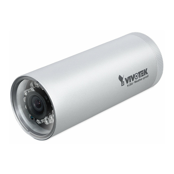
Page 4: Physical Description
Physical Description Front Panel IR LED Lens Light Sensor Back Panel Status LED Reset Button Connectors General I/O Terminal Block Ethernet 10/100 RJ45 Plug Power Cord Socket (Black) EN-3... -
Page 5: Hardware Installation
Hardware Installation 1. Loose the waterproof connector, and then remove the rubber. 2. Loose the back cover. 3. Tear down the aluminum foil vacuum bag and take out the moisture absorber. Attach the supplied moisture absorber to the inner side of the Network Camera. (Please replace the moisture absorber with a new one if you open the back cover after installation.) 4. -
Page 6: Network Deployment
Network Deployment General Connection (without PoE) 1. If you have external devices such as sensors and alarms, make connections from general I/O terminal block. AC24V: 24V+ AC24V AC24V: 24V- AC24V 2. Use the supplied RJ45 female/female : Digital Input GND : Ground coupler to connect the Network Camera to a switch. - Page 7 Power over Ethernet (PoE) When using a PoE-enabled switch The Network Camera is PoE-compliant, allowing transmission of power and data via single Ethernet cable. Follow the below illustration to connect the Network Camera to a PoE-enabled switch via Ethernet cable. PoE Switch When using a non-PoE switch Use a PoE power injector (optional) to connect between the Network Camera and...
-
Page 8: Assigning An Ip Address
"Next" button to continue the program. Installation Wizard 2 3. The program will search for VIVOTEK Video Receivers, Video Servers or Network Cameras on the same LAN. 4. After a brief search, the main installer window will pop up. Double-click on the MAC address that matches the one printed on the camera label or the S/N number on the package box label to open a browser management session with the Network Camera. -
Page 9: Ready To Use
Ready to Use 1. A browser session with the Network Camera should prompt as shown below. 2. You should be able to see live video from your camera. You may also install the 32-channel recording software from the software CD in a deployment consisting of multiple cameras.
Need help?
Do you have a question about the IP8331 and is the answer not in the manual?
Questions and answers