TESTO 549 Instruction Manual
Digital manifolds for maintenance and service work on refrigeration systems and heat pumps
Hide thumbs
Also See for 549:
- Instruction manual (28 pages) ,
- Instruction manual (19 pages) ,
- Instruction manual (26 pages)
Table of Contents
Advertisement
Quick Links
Advertisement
Table of Contents

Related Manuals for TESTO 549


Summary of Contents for TESTO 549
- Page 1 549 - testo 550 . Digital manifold Instruction manual...
-
Page 3: Table Of Contents
Preparing for measurement ............. 9 5.1.1. Switching the instrument On ................9 5.1.2. Connecting temperature probe(s) ..............11 5.1.3. Switching Bluetooth® on and off (only testo 550) ..........11 5.1.4. Measuring mode ....................12 5.2. Performing the measurement ............13 Technical data ..................16 6.1.1. -
Page 4: Safety And The Environment
2 Safety and the environment Safety and the environment 2.1. About this document > Please read this documentation carefully and familiarize yourself with the product before putting it to use. Pay particular attention to the safety instructions and warning advice in order to prevent injuries and damage to the product. -
Page 5: Protecting The Environment
They are intended for use by qualified personnel only. The functions of the testo 549 and testo 550 are designed to replace analog manifolds, thermometers and pressure/temperature charts. Pressures and temperatures can be applied, adapted, tested and monitored. -
Page 6: Overview
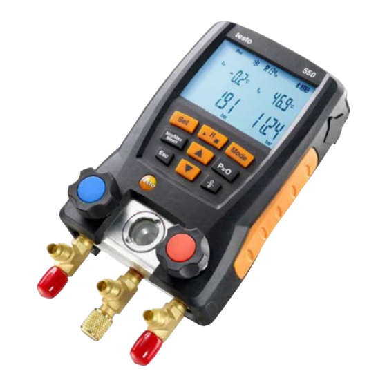
3 Product description 3.2. Overview Display and control elements 1 Mini-DIN probe socket for NTC temperature probe, with socket cover 2 Foldable hanging hook (on rear) 3 D isplay. Instrument status icons: Icon Significance Battery status Bluetooth® Measuring mode 4... -
Page 7: First Steps
4 First steps 5 C ontrol keys: Function [Set] Set units [R, ►, ■] Select refrigerant/ Start/stop / Leakage test [Mode] Change measuring mode to Leak mode [Min/Max/Mean] Display min./max./mean values [▲] Up key: Scroll through menu [P=0] Pressure zeroing Switches to the measurement / home view [▼] Down key: Scroll through menu... - Page 8 4 First steps Units / Parameter selection 1. Press [Set] to confirm or change unit parameter settings [▲] [▼] 2. Press to change the units / parameters. The settings will be accepted once the last selection has been made. Key functions Description [▲]...
-
Page 9: Using The Manifold
5 Using the manifold WARNING Over tightening the valve stem shutoffs may cause: • Damage to the PTFE seal. • Mechanical deformation of the valve piston leading to the PTFE seal falling out. • Damage to the thread of the threaded spindle and the valve screw. - Page 10 > For your own safety you should return the manifold to the Testo Service Department for technical inspection. > You should therefore always replace the refrigerant hoses with new ones after an accidental drop has occurred or after any visible wear and tear.
-
Page 11: Connecting Temperature Probe(S)
5 Using the manifold 5.1.2. Connecting temperature probe(s) Note: The testo 549 does not include temperature probes in the initial scope of delivery. Surface temperature probe At least one NTC temperature probe must be connected to measure the pipe temperature, for automatic calculation of superheating and subcooling. -
Page 12: Measuring Mode
Normal functionality of the digital manifold Automatic If the automatic mode is activated, the mode testo 549 und testo 550 digital manifolds automatically changes the display of the high and low pressure. This automatic change occurs when the pressure on the low-pressure side is 1 bar (15 psi) higher than the pressure on the high-pressure side. -
Page 13: Performing The Measurement
5 Using the manifold 5.2. Performing the measurement WARNING Risk of injury caused by refrigerant that is at high pressure, hot, cold, or poisonous! > Wear safety goggles and protective gloves. > Before pressurizing the measuring instrument: Always fasten the measuring instrument at the hanging hook in order to prevent it from falling (risk of breakage) >... - Page 14 (and temperature) where the refrigerant can still condense • The maximum. permissible pressure of 870 psi (60 bar) is exceeded. Key functions for 550 or 549 when used with optional probes [▲] [▼] > Press to change the reading in the display.
- Page 15 5 Using the manifold Leak test / pressure drop test Systems can be tested for tightness with the temperature- compensated leak test. The system pressure and the ambient temperature are measured over a defined period of time, typically with an inert gas such as Nitrogen. A temperature probe can be connected that measures the ambient temperature.
-
Page 16: Technical Data
Changes The FCC demands that the user be informed that any changes or modifications to the instrument that are not explicitly approved by testo AG may void the user's right to use this instrument. -
Page 17: General Technical Data
6 Technical data 6.1.2. General technical data Characteristic Values Pressure: kPa / MPa / bar / psi Parameters Temperature: °C / °F / K 2 Pressure: sensors, 2 Temperature (NTC Sensors Thermistors) Meas. cycle 0.5 s Pressure connections: 3 x 1/4" SAE Interfaces 2 Temperature NTC measurement channels HP/LP pressure measuring range: -100 to... - Page 18 6 Technical data All refrigerants that are stored in the testo 549 and testo 550 Measurable media Ammonia (R717) and other refrigerants which contain ammonia will damage the manifold Operating temperature: -4 to 122 °F (-20 to 50 °C) Ambient conditions Storage temperature: -4 to 140 °F...
-
Page 19: Maintaining The Product
7 Maintaining the product Maintaining the product Cleaning the instrument Do not use harsh cleaning agents or solvents! Mild soap and water may be used. > Clean instrument using a damp cloth. Keeping connections clean > Keep screw connections clean and free of grease and other deposits, clean with a moist cloth as required. -
Page 20: Tips And Assistance
Changing the valve or valve stem shutoff DO NOT ATTEMPT to change the valve stems. Changing the valve stem shutoff or valves themselves will void the warranty. Send the measuring instrument to Testo Customer Service. Tips and assistance 8.1. Questions and answers... -
Page 21: Error Reports
If you have any questions, please contact your dealer or Testo Customer Service. The contact details can be found on the back of this document or on the Internet at www.testo.com/service- contact. -
Page 22: Ec Declaration Of Conformity
9 EC declaration of conformity EC declaration of conformity... - Page 23 9 EC declaration of conformity...
- Page 24 Testo Inc. 40 White Lake Road Sparta, N. J. 07871 Phone: +1 862 354 5001 Fax: +1 862 354 5020 Email: info@testo.com www.testo.com Headquarter testo AG Testo-Straße 1 79853 Lenzkirch Germany Tel.: +49 7653 681-0 Fax: +49 7653 681-7699 Email: info@testo.de Internet: www.testo.de...
Need help?
Do you have a question about the 549 and is the answer not in the manual?
Questions and answers