TRENDnet TPE-224WS User Manual
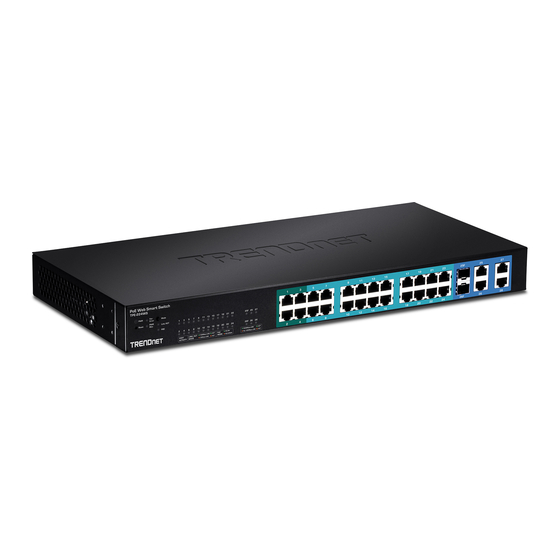
24-port 10/100mbps web smart poe switch with 4 gigabit ports
Hide thumbs
Also See for TPE-224WS:
- User manual (106 pages) ,
- Quick installation manual (23 pages) ,
- Troubleshooting (5 pages)
Table of Contents
Advertisement
Quick Links
FCC Warning
This equipment has been tested and found to comply with the
regulations for a Class A digital device, pursuant to Part 15 of the
FCC Rules. These limits are designed to provide reasonable protection
against harmful interference when the equipment is operated in a
commercial environment. This equipment generates, uses and radiates
radio frequency energy. If not installed and used in accordance with
instructions in this User's Guide, it may cause harmful interference to
radio communications. Operation of this equipment in a residential
area is likely to cause harmful interference, in which case the user will
be required to correct the interference at user's expense.
CE Mark Warning
This is a Class A product. In a domestic environment, this product
may cause radio interference, in which case the user may be required
to take adequate measures.
Advertisement
Table of Contents

Related Manuals for TRENDnet TPE-224WS


Summary of Contents for TRENDnet TPE-224WS
-
Page 1: Fcc Warning
FCC Warning This equipment has been tested and found to comply with the regulations for a Class A digital device, pursuant to Part 15 of the FCC Rules. These limits are designed to provide reasonable protection against harmful interference when the equipment is operated in a commercial environment. - Page 2 UL Warning a) Elevated Operating Ambient Temperature- If installed in a closed or multi-unit rack assembly, the operating ambient temperature of the rack environment may be greater than room ambient. Therefore, consideration should be given to installing the equipment in an environment compatible with the manufacturer's maximum rated ambient temperature (Tmra).
-
Page 3: Table Of Contents
Configuration ..................17 TABLE OF CONT Installing the Web Management Utility ......... 17 About This Guide ................. 1 Discovery List ................18 Purpose .................... 1 Monitor List ................... 19 Terms/Usage ..................1 Device Setting ................ - Page 4 Statistic ..................53 Factory Reset ................54 Backup Setting ................55 Firmware Upload ............... 55 System Reboot ................56 Logout .................... 56 Technical Specifications ..............57...
-
Page 5: About This Guide
ABOUT THIS GUIDE INTRODUCTION Congratulations on your purchase of the TPE-224WS 28-Port This chapter describes the features of the TPE-224WS 28-Port 10/100/1000Mbps Gigabit Ethernet Web Smart PoE Switch. This 10/100/1000Mbps Gigabit Ethernet Web Smart PoE Switch and some device integrates 1000Mbps Gigabit Ethernet, 100Mbps Fast Ethernet... -
Page 6: Fast Ethernet Technology
In addition, the phenomenal bandwidth delivered by Gigabit Ethernet Switching Technology is the most cost-effective method to take advantage of today and tomorrow’s rapidly improving switching and routing internetworking Another approach to pushing beyond the limits of Ethernet technology technologies. And with expected advances in the coming years in is the development of switching technology. -
Page 7: Vlan (Virtual Local Area Network)
VLAN (Virtual Local Area Network) Features A VLAN is a group of end-stations that are not constrained by their 24 x 100BASE-TX Auto-MDIX & Auto-negotiation Fast physical location and can communicate as if a common broadcast Ethernet PoE ports ( Port 1 ~24) domain, a LAN. -
Page 8: Package Contents And Installation
Switch case from scratching. Unpacking Open the box for the Switch and carefully unpacks its contents. The packaging should contain the following items: One TPE-224WS 28-Port 10/100/1000Mbps Gigabit Web Smart PoE Switch Quick Installation Guide Power Cord Utility and User’s Guide CD-ROM Figure 1. -
Page 9: Rack Mounting
Rack Mounting Connecting Network Cable The Switch can be mounted in an EIA standard-size, 19-inch rack, The Switch has 24 10/100Mbps Power over Ethernet ports. These which can be placed in a wiring closet with other equipment. Attach ports runs both in half and full duplex mode using Cat. 5 cables. These the mounting brackets to the Switch’s front panel (one on each side), Power over Ethernet will be automatically activated when a and secure them with the provided screws. -
Page 10: Identifying External Components
These ports support network speeds of either 10Mbps or 100Mbps, IDENTIFYING EXTERNAL COMPONENTS and can operate in half- and full- duplex transfer modes. These ports also support auto-MDIX. Users can use either standard or crossover This chapter describes the front panel and rear panel of the Switch. Ethernet cables. -
Page 11: Rear Panel
Rear Panel Power and System LEDs The rear panel of the Switch consists of an AC power. The following PWR: Power Indicator shows the rear panel of the Switch. : When the Power LED is lit, the Switch is receiving power. When the Power LED is off, the power cord is not connected or is improperly connected. -
Page 12: 1000Base-T/Mini-Gbic Port 25~26 Status Leds
Ethernet network When the mini-GBIC LED is lit, mini-GBIC module is plugged into the mini-GBIC slot. PoE Status No mini-GBIC module inserted. Green : When the PoE Status light is green, the PoE powered device (PD) is connected and the port supplies power normally. 1000BASE-T Port 27~28 Status LEDs : When the PoE Status light is red, the PoE port has failed due to one of the following scenarios:... -
Page 13: Configuration
Follow the on-screen instructions to install the utility. Double click or press “Add to monitor list” to select add a device to Upon completion, go to Program Files TRENDnet the Monitor List. Smart Switch Management Utility and open the Web Smart... -
Page 14: Monitor List
System word definitions in the Discovery List: View Trap: The Trap function allows you to monitor events that occur with the Switches in the Monitor List. IP Address: Shows the current IP address of the device. There is an LED indicator next to the “View Trap” button. When the MAC Address: Shows the MAC Address of the Switch. -
Page 15: Device Setting
Device Setting Configuration Setting: Under Configuration Setting, you can set the IP Address, Subnet Mask, Gateway, Set Trap to (Trap IP Address), System name, Location and DHCP function. Select the device in the Discovery list or Monitor List and click Configure Settings. -
Page 16: Configuring The Switch
Configuring the Switch Monitor List. Exit: To exit the utility. The TPE-224WS 28-Port 10/100/1000Mbps Gigabit Ethernet Web Smart PoE Switch has a Web GUI interface for smart switch There are four options under “View”; view log and clear log function. -
Page 17: Setup Setting
You can also access the browser configuration through the utility Setup Setting program. Select the device shown in the Monitor List and then click “Web Configuration”. When the login screen appears, enter the The following seven links appear under Configuration Setting: Port default password "admin"... -
Page 18: Port Settings
Power Limit: Speed: This function allows you to manually setting the port power current The 1~24 100BASE-TX port connections can operate in Forced Mode limitation assigned to the Powered Device. To protect the Switch and settings (100M Full, 100M Half, 10M Full, 10M Half), Auto, or the connected device, the power limit function will disable the PoE Disable. -
Page 19: Ieee 802.1Q Vlan
Untag Asymmetrick VLAN Settings: IEEE 802.1Q VLAN The IEEE 802.1Q VLAN configuration page provides powerful VID A VLAN is a collection of ports that make up a single broadcast management functions. The original default VLAN setting has the domain. VID as 01, named “default”, and contains all ports as “Untagged”. VLANs can be easily organized to reflect department groups (such as R&D, Marketing), usage groups (such as e-mail), or multicast groups (multimedia applications such as video conferencing). - Page 20 VID: A unique VLAN ID. To change existing IEEE 802.1Q VLAN settings, press the VID to modify that IEEE 802.1Q VLAN setting. VLAN Name: A VLAN name can be setting as user wish. Port: The switch port number. Untag: Outgoing frames without VLAN tag. Tag: Outgoing frames with VLAN tag.
- Page 21 PVID settings: Step 1: Set VLAN 1 member port 15~28 to “Net Member” ports then apply settings While receiving an untagged frame from the port, the switch will assign a tag to the frame, using the PVID of the port as its VID. Here is an example of two VLAN groups with several ports on each group and VLAN 1 (VID 01) does not have communication with VLAN 2 (VID 02).
- Page 22 Example 2: Step 3: Create VID 02 and set port 1~5 to “Untag” ports and port 6~28 to “Not Member” ports then apply settings. 802.1Q Asymmetric VLAN settings example: port 1~24 in VLAN1, port 1~5 in VLAN 2, port 1/6~9 in VLAN 3. All VLAN1~3 have access to internet via port 1.
- Page 23 Step 5: Set PVID port 3~9 as shown in the below list then complete. Example 3: Note: Create two VLAN groups for Tag ports multi-need server application setting and two 1. Untag port VLAN member can exist in different VLAN groups simultaneously when VLAN clients cannot negotiate to each other.
- Page 24 Note: The multi-need server must be support IEEE 802.1Q VLAN, the sever uplink port is port1. The Tag port can exist in the different VLAN group simultaneously even Asymmetric VLAN function is disabled. Step 2: Create VID 02 and set port 1 to “Tag” port and port 9~28 to “Untag” ports then apply settings.
-
Page 25: Trunk Setting
Trunk Setting Mirror Setting The Trunking function enables the cascading of two or more ports to Port Mirroring is a method of monitoring network traffic that forwards increase bandwidth. Up to six Trunk groups may be created, each a copy of each incoming and/or outgoing packet from one port of the supporting up to 8 ports. -
Page 26: Ieee 802.1P Default Priority
IEEE 802.1p Default Priority Broadcast Storm Control Setting This feature displays the Quality of Service priority levels of each The Broadcast Storm Control feature provides the ability to control port. For packets that are untagged, the Switch will assign the the receive rate of broadcasted packets. -
Page 27: Igmp Snooping Setting
Query Interval (60-600 sec): The Query Interval is the interval IGMP Snooping Setting between General Queries sent. By adjusting the Query Interval, the number of IGMP messages can increase or decrease; larger values Find that there are two items, including IGMP Global Setting and cause IGMP Queries to be sent less often. -
Page 28: Igmp Vlan Setting
Router Timeout (60-600 sec): This is the interval after which a learnt router port entry will be purged. For each router port learnt, a 'RouterPortPurgeTimer' runs for 'RouterPortPurgeInterval'. This timer will be restarted whenever a router control message is received over that port. -
Page 29: System Setting
PoE System Setting System Setting This PoE System Setting page will display the PoE status including The following links appear under System Settings: System System Budget Power, Support Total Power, Remainder Power, and Information, System Setting, Trap Setting, Password Setting, the ratio of system power supply. -
Page 30: System Setting
Trap Setting System Setting By configuring the Trap Setting, it allows you to monitor specified System Setting includes IP Information and System information. events on this Web-Smart Switch through the Web Management There are two ways to configure an IP Address on the Switch: Static Utility. -
Page 31: Password Setting
Refresh: To renew the details collected and displayed. Password Setting Clear Counter: To reset the details displayed. Setting a password is an invaluable tool for managers to secure the To view the statistics of individual ports, click one of the Port ID as Web Smart PoE Switch. -
Page 32: Backup Setting
Backup Setting System Reboot The backup setting option allows you to save the current settings of Provides a safe way to reboot the system. Ensure the configuration has the Switch. Click the “Backup” button to save settings. been saved before performing a system reboot. Changes you have made may be lost after system reboot. -
Page 33: Technical Specifications
TECHNICAL SPECIFICATIONS Power over Ethernet Standard IEEE 802.3af General Power current Up to 15.4W per PoE port Standards IEEE 802.3 10BASE‐T Ethernet PD Classification Maximum 170W for all PoE ports IEEE 802.3u 100BASE‐TX Fast Ethernet PoE pin IEEE 802.3ab 1000BASE‐T Gigabit Ethernet Auto PD classification identify assignment IEEE 802.3z 1000BASE‐SX/LX Gigabit Ethernet Safety protection Power(+): pin 3 & pin 6 in RJ‐45 IEEE 802.3af Power over Ethernet Power(‐): pin 1 & pin 2 in RJ‐45 Protocol CSMA/CD Performance Data Transfer Ethernet: 10Mbps (half‐duplex), 20Mbps (full‐duplex) Rate Fast Ethernet: 100Mbps (half‐duplex), 200Mbps (full‐duplex) Transmits Store‐and‐forward Method: Gigabit Ethernet: 2000Mbps (full‐duplex) Topology Star RAM Buffer: 1Mbits per device Network Cables ... -
Page 34: Limited Warranty
If a product does not operate as warranted above during the applicable warranty period, TRENDnet shall, at its option and expense, repair the defective product or deliver to customer an equivalent product to replace the defective item. All products that are replaced will become the LIMITATION OF LIABILITY: TO THE FULL EXTENT ALLOWED BY LAW TRENDNET ALSO property of TRENDnet.
Need help?
Do you have a question about the TPE-224WS and is the answer not in the manual?
Questions and answers