Table of Contents
Advertisement
Quick Links
Instruction Manual
Form 5592
January 1999
Design RSS Lined Valve
Contents
. . . . . . . . . . . . . . . . . . . . . . . . . . . . . . .
. . . . . . . . . . . . . . . . . . . . . . . . . . . . .
. . . . . . . . . . . . . . . . . . . . . . . . . . . . . . . . . .
. . . . . . . . . . . . . . . . . . . . . . . . . . . . . . .
. . . . . . . . . . . . . . . . . . . . . . . . . . . . . . . .
. . . . . . . . . . . . . . . . . . . . . . . . . . . . . .
. . . . . . . . . . . . . . . . . . . . . . . . .
. . . . . . . . . . . . . . . . . . . . . . . . . . . .
. . . . . . . . . . . . . . . . . . . . . . . . . . . . . . .
. . . . . . . . . . . . . . . . . . . . . . . . . . . . . . . . . .
. . . . . . . . . . . . . . . . . . . . . . . . . . . .
. . . . . . . . . . . . . . . . . . . . . . . . . . . . . . . . .
Introduction
Scope of Manual
This instruction manual includes installation, mainte-
nance, and parts information for 1/2- through 4-inch
Design RSS lined globe valves. Refer to separate
manuals for instructions covering the actuator, posi-
tioner, and accessories.
Description
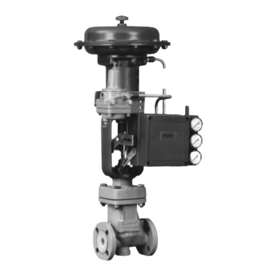
The Design RSS lined globe-style valve (figure 1) has
pure-modified PTFE trim parts, push-down-to-close
action, and positive shutoff. This valve is intended for
applications involving severely corrosive and toxic
flowing media. The Design RSS valve body provides
an economical alternative to alloy valve bodies in a
wide variety of applications.
Only personnel qualified through training or experience
should install, operate, and maintain this control valve.
1
1
1
1
3
5
5
. . . . . . . . .
5
7
7
8
9
11
W4453-1 / IL
Figure 1. Design RSS Valve with Type 667 Actuator
If you have any questions concerning these instruc-
tions, contact your Fisher Controls sales office or
sales representative before proceeding.
Specifications
Specifications for the Design RSS valve are shown in
table 1. If the valve is shipped with the actuator, some
of the valve specifications are on the valve nameplate,
which is attached to the actuator. If the valve is
shipped without the actuator, the valve nameplate is
wired to the valve.
Design RSS
and Type 3582 Positioner
Advertisement
Table of Contents

Related Manuals for Fisher Design RSS


Summary of Contents for Fisher Design RSS
-
Page 1: Table Of Contents
1/2- through 4-inch W4453–1 / IL Design RSS lined globe valves. Refer to separate Figure 1. Design RSS Valve with Type 667 Actuator manuals for instructions covering the actuator, posi- and Type 3582 Positioner tioner, and accessories. - Page 2 Application Limits Liquid Service: 0.6. For cavitating 1/2, 3/4, 1, 1-1/2, 2, 3, and 4 inches 1 abs applications, contact your Fisher Controls sales of- fice or sales representative. Face-To-Face and Flange Compatibility Gas Service: Velocity 0.33 MACH DUCTILE IRON...
-
Page 3: Installation
2, or figure 2. To avoid such injury or ranges, do not apply any other condi- damage, use pressure-limiting or pres- tions to the valve without first contact- sure-relieving devices to prevent service ing your Fisher Controls sales office or conditions from exceeding these limits. sales representative. - Page 4 (key 20, not shown) and install the leak-off position. Before installing in any other orientation, con- piping into the tapping in the bonnet (key 2, figure 9). sult your Fisher Controls sales office or sales repre- sentative. 5. If continuous operation is required during inspec-...
-
Page 5: Maintenance
Key numbers are shown in figure 9. Due to the care Fisher Controls takes in meeting all 1. Isolate the control valve from the line pressure. Re- manufacturing requirements (heat treating, dimension- lease pressure from both sides of the valve and drain al tolerances, etc.), use only replacement parts sup-... - Page 6 Design RSS VALVE STEM (KEY 5) LOCKNUT TRAVEL STOP (KEY 10) (KEY 16) 0.020 INCH (0.5 mm) GAP YOKE LOCKNUT (KEY 14) BONNET (KEY 2) EQUAL AT ALL BONNET BOLTING LOCATIONS LOCATING DIAMETER BELLOWS SEAT RING (KEY 6) CONTACT SURFACE...
-
Page 7: Trim Maintenance
Design RSS W4471 / IL W4472 / IL Figure 6. Typical Locking Rope Installation 10. Tighten the cap screws and hex nuts (keys 7 and 13. Thread the travel stop (key 16) onto the valve 8) in a crisscross pattern to a maximum torque value stem until there is a 0.020 inch (0.5 mm) gap between... -
Page 8: Assembly
W4473 / IL 53.98 63.88 71.83 7.92 1-1/2 7.14 5.55 222.25 54.23 64.13 72.62 7.62 Figure 7. Design RSS Valve Body Shown with Tool 65.07 76.20 83.72 7.92 7.14 5.55 222.25 Used to Remove or Install Seat Ring 65.33 76.45 84.53 7.62 91.26... -
Page 9: Parts Ordering
(figure 6). bellows and choose the appropriate part number. If you need assistance, contact your Fisher Controls 3. Install the assembled valve plug, bellows, and sales office or sales representative. Be sure to provide valve stem (keys 3, 6, and 5). - Page 10 SEE VIEW B 40B4191–E / IL NOTE: KEYS 17, 18, 19, 20, 21, 22, 23, 24, 25, 26, AND 30 ARE NOT SHOWN BELLOWS BELLOWS RETAINER LOCKING ROPE VALVE PLUG A3598–3 / IL VIEW B Figure 9. Design RSS Valve Assembly...
-
Page 11: Parts List
Design RSS BELLOWS (KEY 6) LOCKING ROPE (KEY 9) VALVE PLUG ASSEMBLY (KEY 3) SEAT RING (KEY 4) NOTES: ORIGINAL AND NEW DESIGN PARTS ARE NOT INTERCHANGEABLE. SEE PARTS ORDERING SECTION FOR DETAILS. A5243 / IL Figure 10. Original and New Valve Plug and Seat Ring Design... - Page 12 Design RSS Description Part Number Description Part Number Travel Stop Seat Ring Tool (for use only if Stainless steel specified--see figure 7 or 8), steel 1/2, 3/4, 1, 1-1/2, & 2-inch 20B2500X032 1/2 & 3/4-inch 20B4538X012 3 & 4-inch 20B2499X032...
- Page 13 Design RSS Key 3* Valve Plug for 5/16- through 4-inch (8 through 96 mm) Port Diameters (Includes Locking Rope, Key 9) PORT ORIGINAL SLIP-ON DESIGN THREADED-ON DESIGN VALVE DIAMETER DIAMETER SIZE SIZE, SIZE, Glass-Filled Glass-Filled Carbon-Filled Carbon-Filled PTFE, TFM1600 INCHES...
- Page 14 *Recommended spare parts Fisher, Fisher-Rosemount, and Managing The Process Better are marks owned by Fisher Controls International, Inc. or Fisher-Rosemount Systems, Inc. All other marks are the property of their respective owners. Fisher Controls International, Inc. 1986, 1999; All Rights Reserved...
Need help?
Do you have a question about the Design RSS and is the answer not in the manual?
Questions and answers