ersa DIGITAL 2000 A Operating Instructions Manual
Microprocessor-controlled
soldering station
Hide thumbs
Also See for DIGITAL 2000 A:
- Operating instructions manual (61 pages) ,
- Operating instructions manual (50 pages)
Table of Contents
Advertisement
Advertisement
Table of Contents

Related Manuals for ersa DIGITAL 2000 A


Summary of Contents for ersa DIGITAL 2000 A
- Page 1 Betriebsanleitung • Operating instructions ERSA DIGITAL 2000 A...
-
Page 2: Table Of Contents
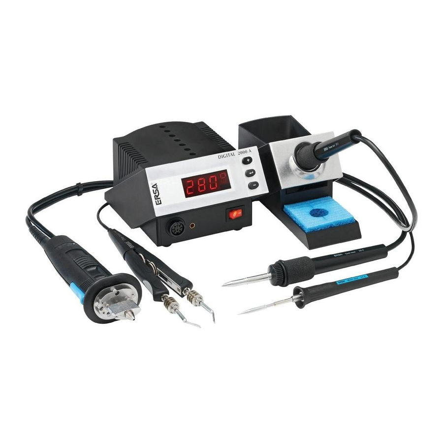
Inhaltsverzeichnis Contents Einführung Introduction Technische Daten Technical Data Sicherheitshinweise Safety information Inbetriebnahme Starting operation Funktionsbeschreibung Functional description Fehlerdiagnose und Error diagnosis and Fehlerbehebung Troubleshooting Wartung und Instandhaltung Maintenance and Servicing Ersatzteile und Replacement parts and ordering Bestelldaten information Garantie Warranty... - Page 3 DIGITAL 2000 Abb. 1 / fig. 1 DIGITAL 2000 A 12 11 14 15 1. Anzeige 9. Viskoseschwamm 1. Display 9. Viscose sponge 2. Versorgungseinheit 10. Netzschalter 2. Supply unit 10. Power switch 3. Bedienungstasten 11. Potentialausgleichsbuchse 3. Control buttons 11.
-
Page 4: Einführung
We appreciate your decision to purchase this hochwertigen Lötstation entschieden haben. high-quality soldering station. The DIGITAL ERSA stellt mit der DIGITAL 2000 A eine mikro- 2000 A from ERSA is a top-of-the-line micro- prozessorgeregelte Lötstation der Spitzenklasse processor-controlled soldering station. It is zur Verfügung. - Page 5 Einführung Introduction Ausstattungsmerkmale: Equipment features: • Antistatikausführung • Antistatic design • Potentialausgleich • Potential equalisation • Vollwellensteuerung • Full-wave control • 24 V Kleinspannung für Lötkolben • 24 V small voltage for soldering irons • Prüfzeichen VDE-GS, CE, VDE-EMV • VDE-GS, CE, VDE-EMC marks of conformity 1.2 Löt- und Entlötwerkzeuge 1.2 Soldering and Desoldering Tools Tech tool...
- Page 6 Der Chip tool ist zum Auslöten von SMT- The Chip tool is designed for desoldering SMT Komponenten entwickelt worden. Für dieses components. ERSA provides an extensive range Werkzeug stellt ERSA ein umfangreiches Spit- of tips for this tool, for desoldering all current zensortiment zur Verfügung, mit dem Sie von...
- Page 7 X-tool to any desoldering task. For anzupassen. Weitere Hinweise zum Arbeiten mit further information on working with the X-tool, dem X-Tool entnehmen Sie bitte der Betriebsan- please consult the „ERSA X-Tool“ Operating leitung „ERSA X-Tool“ (3BA00023-00). Instructions (3BA00023-00). Temperaturfühler Temperature sensor Über den Temperaturfühler können in Verbin-...
-
Page 8: Technische Daten
Technische Daten Technical Data Lötstation DIGITAL 2000 A DIGITAL 2000 A soldering station Elektronikstation DIG 203 A DIG 203 A electronics station Versorgungsspannung: 230 V~, 50-60 Hz Supply voltage: 230 V~, 50-60 Hz Sekundärspannung: 24 V~ Secondary voltage: 24 V~... - Page 9 Technische Daten Technical Data Lötkolben Tech tool Tech tool soldering iron Spannung: 24 V~ Voltage: 24 V~ Leistung: 70 W / 280° C (536° F) – 60 W / Output: 70 W / 280° C (536° F) – 60 W / 350°...
- Page 10 Technische Daten Technical Data Entlötpinzette Chip tool Desoldering pincette Chip tool Spannung: 24 V~ Voltage: 24 V~ Leistung: 2 x 30 W / 280° C (536° F) – Output: 2 x 30 W / 280° C (536° F) – 2 x 20 W / 350° C (662° F) 2 x 20 W / 350°...
- Page 11 Technische Daten Technical Data Temperaturfühler Temperatur sensor Temperaturmessung: Temperature measurement: Ni-CrNi-Thermoelement (Typ K) Ni-CrNi thermocouple (type K) FE-CuNi-Thermoelement (Typ J) FE-CuNi thermocouple (type J) Messbereich (Raumtemperatur): Measuring range (room temperature): Typ K: 50° – 600° C (122° – 1112° F) K-type: 50°...
- Page 12 Sicherheitshinweise Safety information Bitte beachten Sie vor der Inbetriebnahme Before commissioning, be sure to note the unbedingt beiliegenden Sicherheitshin- enclosed safety information. weise.
-
Page 13: Sicherheitshinweise
Inbetriebnahme Starting operation 4.1 Vor der Inbetriebnahme 4.1 Before Commissioning Bitte prüfen Sie den Inhalt der Verpackung auf Please check that the contents of the package Vollständigkeit. Er besteht aus: are complete. Contents: • Versorgungseinheit • Supply unit • Netzanschlusskabel •... - Page 14 Inbetriebnahme Starting operation Für einen sicheren und dauerhaften Einsatz Observe the following points for safe and eines Lötwerkzeuges und der Lötspitze sind die long-lasting use of the soldering tool and folgenden Punkte unbedingt zu beachten: soldering tip: • Den Lötkolben bitte nicht gegen harte Gegen- •...
- Page 15 Inbetriebnahme Starting operation 4.2 Erstes Einschalten 4.2 Switching On for the First Time Bitte lesen Sie diese Betriebsanleitung vor der Please read through these Operating ersten Inbetriebnahme vollständig durch. Instructions completely before commissioning. Für die Inbetriebnahme gehen Sie nach den Procedure for commissioning: folgenden Schritten vor.
- Page 16 Kontakt gebracht wird. connection. • Lötdraht zuführen (z.B. ERSA-Lötdraht • Add solder wire (e.g. ERSA Sn95,5Ag3,8Cu0,7 Sn95,5Ag3,8Cu0,7 nach EN 29454 mit solder wire with flux core according to EN Flussmittelseele). 29454). • Lötvorgang wiederholen. • Repeat soldering procedure.
- Page 17 Inbetriebnahme Starting operation 4.4 Hinweise zum Entlöten mit dem 4.4 Instructions for desoldering using Chip tool Chip tool • Die sauberen und fettfreien Lötstellen der zu • Using a small brush, wet the clean and grease- entlötenden Bauteile mit einem Pinsel mit free soldering joints of the components to be Flussmittel benetzen.
- Page 18 Die Entlöteinsätze müssen stets verzinnt sein. The desoldering inserts must always be tin- coated. Auf Wunsch erhalten Sie kostenlos eine detail- You can receive a detailed process description lierte Prozessbeschreibung „SMD Entlöten“ von ‘SMD Removal‘ free of charge upon request from ERSA. ERSA.
-
Page 19: Functional Description
Funktionsbeschreibung Functional description 5.1 Die Programme 5.1 The Programs Die DIGITAL 2000 A verfügt über fünf vonein- The DIGITAL 2000 A has five independent ander unabhängige Programme. In diesen programs. settings different Programmen sind die Einstellungen für die (soldering) tools are saved in these programs verschiedenen Tools (Lötwerkzeuge) gespeichert... - Page 20 The ERSA Tool Selector allows four different vier verschiedene Löt- und Entlötwerkzeuge im soldering and desoldering tools to be used Wechsel an der DIGITAL 2000 A zu betreiben. alternately at the DIGITAL 2000 A. Beim Umschalten am Tool Selector erkennt die When the Tool Selector is switched, the DIGITAL 2000 A das jeweilige Tool und führt...
- Page 21 Funktionsbeschreibung Functional description 5.2 Das Menüsystem 5.2 The Menu System Das Bedienungskonzept der DIGITAL 2000 A The operating concept of the DIGITAL 2000 ermöglicht es, mit nur drei Bedientasten alle A allows you easily to use all setting options Einstellmöglichkeiten einfach nutzen.
- Page 22 Funktionsbeschreibung Functional description Zur Orientierung innerhalb der Menüstruktur wird To assist your navigation within the menu in der vierten Stelle des Displays immer ein dem structure, a symbol corresponding to the menu Menüpunkt zugehöriges Symbol blinkend ange- item always flashes in the fourth position of the zeigt.
- Page 23 Funktionsbeschreibung Functional description 5.2.1 Parametereinstellung 5.2.1 Parameter Setting In Abbildung 4 wird das Schema für die Para- Figure 4 shows the flow chart for parameter metereinstellung dargestellt. setting. Abb. 4 / fig. 4 Istwertanzeige / actual value display 4. Digit °...
- Page 24 Funktionsbeschreibung Functional description 5.2.2 Beschreibung des Ablaufschemas 5.2.2 Description of the Flow Chart Ausgehend von der Istwertanzeige wird der Starting from the actual value display, the jeweils nächste Menüpunkt über die ENTER next menu point in each case is reached via Taste erreicht.
- Page 25 Funktionsbeschreibung Functional description 5.3 Beschreibung der Funktionen 5.3 Description of the Functions 5.3.1 Sollwert Funktion ( ° 5.3.1 Setpoint Function ( ° Die Einstellung des gewünschten Temperatur- The desired soldering tip temperature setpoint Sollwertes an der Lötspitze erfolgt im ersten is set in the first menu item (see flow chart in Menüpunkt (siehe Ablaufschema Abbildung 4) Figure 4) by means of the (+) and (-) keys.
- Page 26 Funktionsbeschreibung Functional description 5.3.3 Standby Funktion (S) 5.3.3 Standby Function (S) Diese Funktion schaltet die Lötstation in einen This function switches the soldering station to a Bereitschaftszustand, wenn über state of readiness if it has not been used over eingestellten Zeitraum nicht benutzt wird. Ziel a preset period of time.
- Page 27 Funktionsbeschreibung Functional description Einschränkungen der Standby Funktion: Restrictions of the standby function: Die Standby Funktion arbeitet mit dem Tech tool, The standby function is not restricted with the X-Tool und dem Power tool ohne Einschränkung. Tech tool, the X-Tool and the Power tool. Hingegen erlaubt es das Zeitverhalten von Micro On the other hand, the time characteristics of the tool und Chip tool nicht, ein Arbeiten sicher zu...
- Page 28 Funktionsbeschreibung Functional description Tabelle 4 / Table 4 Tabelle 5 / Table 5 Tabelle 6 / Table 6 Tabelle 7a / Table 7a Tabelle 7b / Table 7b Tabelle 5: Tip Offset Nummern für den Micro tool Tabelle 7b: Table 5: Tip Offset Nummern Tip Offset numbers für den Power tool...
- Page 29 The Tech tool can otherwise not be optimally falls nicht optimal geregelt werden. controlled. Weitere Hinweise zur Verwendung des X-Tool For further information on using the X-tool, please entnehmen Sie bitte der Betriebsanleitung „ERSA consult the „ERSA X-tool“ Operating Instructions X-Tool“ (3BA00023-00). (3BA00023-00). 5.3.5 Kalibrierfunktion (C) 5.3.5 Calibration Function (C)
-
Page 30: Funktionsbeschreibung
5. Funktionsbeschreibung Functional description 5.3.6 Energiefunktion (E) 5.3.6 Energy Function (E) Die Energiefunktion gestattet dem Anwender, The energy function allows the user to influence das Regelverhalten der Station zu beeinflussen, the control characteristics of the station, so that wodurch das Auf- und Nachheizverhalten der heating and re-heating by the station can be Station auf das jeweilige Einsatzgebiet ange- adapted to the given area of application. - Page 31 5. Funktionsbeschreibung Functional description 5.3.7 Passwortfunktion (P) 5.3.7 Password Function (P) Über die Passwortfunktion kann die Station vor By means of the password function, the station unbeabsichtigten und unbefugten Parameter- can be protected against accidental or unautho- veränderungen geschützt werden. Als Passwort rized parameter changes.
- Page 32 5. Funktionsbeschreibung Functional description...
- Page 33 5. Funktionsbeschreibung Functional description Wurde das Passwort falsch eingegeben, kann der If the password was not entered correctly, the Parameter nicht verändert werden. Über (+)/(-) parameter cannot be changed. The password Tasten wird die Passwortüberprüfung erneut check is indicated again via (+)/(-) keys. The angezeigt.
- Page 34 Spitzenhalters the tip holder attached to the tool holder. gewechselt werden. When changing the desoldering tip, proceed Verfahren Sie zum Wechseln der Entlötspitze as described in the „ERSA X-Tool“ Operating wie in der Betriebsanleitung „ERSA X-Tool“ Instructions (3BA00023-00). (3BA00023-00) angegeben.
- Page 35 5. Funktionsbeschreibung Functional description Power tool Power tool Das Austauschen der Lötspitze ist mit Hilfe einer The soldering tip can also be replaced when hot Flachzange auch im heißen Zustand möglich. by means of flat-nosed pliers. • Federhaken aus der Spitzenbohrung heben •...
- Page 36 5. Funktionsbeschreibung Functional description Lötspitzen- Entlöteinsatzwechsel Changing the soldering tips and desoldering inserts Die Lötspitze bzw. die Entlöteinsätze müssen The soldering tip and / or the desoldering inserts bei Verschleiß oder wenn eine andere Lötspit- must be changed if they are worn, or if a different zen- bzw.
- Page 37 5. Funktionsbeschreibung Functional description Einstellen der Entlöteinsätze am Adjusting the desoldering inserts Chiptool on the Chip tool • Stellring auf den Entlöteinsatz aufschieben • Push up the adjusting collar set on the und anschließend auf den Chip tool stecken. desoldering insert, and then connect it to the Dabei muss der Fixierstift am Stellring in den Chip tool.
- Page 38 5. Funktionsbeschreibung Functional description Hinweis: Note: Bei längeren Arbeitspausen empfehlen wir When not using the Chip tool for a long period of durch Verstellen der Rändelschraube (3) den time, please open the angle to its widest position Öffnungswinkel möglichst groß zu halten (Scho- using the knurled head screw 3.
- Page 39 5. Funktionsbeschreibung Functional description 5.5 Werkseitige Voreinstellungen 5.5 Factory Pre-Settings In der nachstehenden Liste sind die werkseiti- The following is a list of the factory pre-settings gen Voreinstellungen der einzelnen Programme for the individual programs. aufgeführt. Tabelle 8: Werkseitige Voreinstellungen Table 8: Factory Pre-Settings Weitere Einstellungen: Other settings:...
- Page 40 5. Funktionsbeschreibung Functional description 5.7 Arbeiten mit empfindlichen 5.7 Working with sensitive Bauelementen components Manche Bauelemente können durch elektrostati- Many components may be damaged by electro- sche Entladung beschädigt werden (beachten Sie static discharge (please observe the warnings on bitte die Warnhinweise auf den Verpackungen oder the packaging or ask the manufacturer or supplier).
- Page 41 5.8 Calibrating the soldering station Grundsätzlich stehen an der DIGITAL 2000 A Two calibrating functions are in principle available on the DIGITAL 2000 A. The two functions were zwei Kalibrierfunktionen zur Verfügung. Die beiden already mentioned in sections 5.3.4: Tip Offset Funktionen sind bereits in 5.3.4 Tip Offset Funk-...
- Page 42 Functional description • Ermitteln der Temperatur der Lötspitze mit • Determine the temperature of the soldering einem kalibrierten Messgerät (z.B. ERSA tip using a calibrated gauge (e.g. ERSA DTM 100). DTM 100). • Vergleichen der beiden Anzeigewerte. • Compare the two display values.
- Page 43 5. Funktionsbeschreibung Functional description Standby-Betrieb Stand-by mode Wird die Station mit einer Standy Zeitvorgabe In the stand-by operating mode a flashing betrieben, zeigt die blinkende Isttemperatur- actual temperature display indicates that the anzeige an, daß die Lötstation den Lötkolben auf soldering station adjusts the soldering iron’s die Standbytemperatur (200°C / 390°F) regelt.
-
Page 44: Fehlerdiagnose Und
Fehlerdiagnose Error Diagnosis und -behebung and Troubleshooting 6.1 Allgemeine Fehler 6.1 General Errors Sollte die Lötstation nicht den Erwartungen If the soldering station does not operate as entsprechend funktionieren, prüfen Sie bitte die expected, check the following items: folgenden Punkte: •... - Page 45 Table 9. Error messages may werden. Fehlermeldungen können auch über also be confirmed with the control buttons. die Bedientasten quittiert werden. Tabelle 9: Fehlercodes der DIGITAL 2000 A Table 9: Error Codes of the DIGITAL 2000 A...
- Page 46 Fehlerdiagnose Error Diagnosis und -behebung and Troubleshooting 6.3 Sonstige Fehler 6.3 Other Errors Es können noch weitere Fehler auftreten, die auf Other errors may also occur, indicating possible mögliche Defekte des Lötwerkzeugs hinweisen. defects in the soldering tool. Diese sind: These errors are: •...
- Page 47 Fehlerdiagnose Error Diagnosis und -behebung and Troubleshooting Chip tool Chip tool Anleitung für die Demontage Dismantling steps Abbildung der Steckerstiftanordung auf der Anschlusstülle. Diagram of connector pin arrangement on connection socket. Heizkörper paarweise austauschen. Replace heating elements in pairs. Einbaulage der Blattfeder kurze Seite oben. Installation position of leaf spring with short side up.
- Page 48 Fehlerdiagnose Error Diagnosis und -behebung and Troubleshooting Heizkörperwechsel beim Chip tool Chipp tool - Changing the heating element Lötstation ausschalten und Anschlusstülle vor- sichtig in Pfeilrichtung (1) abziehen. Switch off the soldering station and carefully pull Den Entlöteinsatz wie unter Punkt. 5.3 beschrie- off the connecting sleeve in the direction of the ben abziehen (2).
- Page 49 (-)/ green Verfahren Sie zum Wechseln der Heizelemente When changing the heating elements, proceed earth red (+), thermocouple wie in der Betriebsanleitung „ERSA X-Tool“ as described in the „ERSA X-Tool“ Operating thermocouple green (-) (3BA00023-00) angegeben. Instructions (3BA00023-00).
-
Page 50: Wartung Und Instandhaltung
7.1 Important care jobs Hinweis: Note: Verwenden Sie ausschließlich Original ERSA Only use genuine ERSA consumables and Verbrauchs- und Ersatzteile, um sichere Funk- spare parts in order to ensure reliable function tion und Gewährleistung zu erhalten! and to maintain the unit‘s warranty. -
Page 51: Ersatzteile Und Bestelldaten
Ordering Information Bezeichnung Bestell-Nr. Description Order no. Stationen: Stations: Elektronikstation DIGITAL 2000 A, 0DIG 20 A 84 DIGITAL 2000 A electronic 0DIG 20 A 84 80 W, antistatisch, komplett mit station, 80 W, antistatic, compl. Lötkolben Power tool with Power tool soldering iron... - Page 52 Ersatzteile und Replacement Parts and Bestelldaten Ordering Information Bezeichnung Description Order No. Bestell-Nr. Lötkolben Micro tool, 24V, 20 W, Micro tool soldering iron, 24V, 0270 BDJ 0270 BDJ antistatisch mit Spitze 212 BD 20 W, antistatic with tip 212 BD Entlötpinzette Chip tool, 24V, 0450 MDJ Desoldering Pincette Chip tool,...
- Page 53 Heater insert for X-tool 072100J012 Thermoelement without thermocouple 0003B Viskoseschwamm für Viscose sponge for holder 0003B Ablageständer For other single parts for the Weitere Einzelteile für den X-tool, see the „ERSA X-Tool“ X-Tool siehe Betriebsanleitung Operating Instructions „ERSA X-Tool“ (3BA00023-00). (3BA00023-00).
- Page 54 Ersatzteile und Replacement Parts and Bestelldaten Ordering Information Tech tool Micro tool X-tool ERSADUR-Dauerlötspitzen ERSADUR-Dauerlötspitzen ERSADUR-Entlötspitzen ERSADUR soldering tips ERSADUR soldering tips ERSADUR desoldering tips 0722 EN 0818 0612 SD* 0212 SD* 0722 EN 0823 0612 UD 0212 BD* 0722 EN 1020 0612 BD 0212 CD 0722 EN 1023...
- Page 55 Ersatzteile und Replacement Parts and Bestelldaten Ordering Information Entlöt Pincette Chip tool / Desoldering pincette Chip tool Entlöteinsätze / Desoldering inserts 0422 ED 0422 FD7 0422 QD3 6 mm/SOIC 8 17,5 mm/PLCC 48 25 mm/SOIC 40 0422 FD10 4 mm/SOIC 16 0422 QD4 0422 FD8 20 mm/PLCC 52...
- Page 56 Ersatzteile und Replacement Parts and Bestelldaten Ordering Information Power tool ERSADUR-Dauerlötspitzen Verstärkte ERSADUR-Dauerlötspitzen IC-Auslöteinsätze ERSADUR soldering tips ERSADUR reinforced soldering tips IC desoldering inserts 0832 BD 0832 GD 0832 C8/7,62 0832 CD 0832 C14/7,62 0832 LD 0832 ED 0832 C16/7,62 0832 MD 0832 KD 0832 C18/7,62...
- Page 57 Ersatzteile und Replacement Parts and Bestelldaten Ordering Information Power tool ERSADUR-Dauerlötspitzen ERSADUR soldering tips 0842 YD 0842 UD* 0842 ED 0842 CD 0842 SD 0842 ID 0842 BD 0842 KD 0842 JD *Achtung! Vor dem Aufheizen Schlauch-Schutztülle entfernen! *Consideration! Before you start to solder please remove the hose protection nozzle.
-
Page 58: Warranty
Warenrücksendung beiliegen. shipment. ERSA GmbH • Leonhard-Karl-Str. 24 • 97877 Wertheim / Germany Tel. +49 (0) 9342/800-0 • Fax -100 • e-mail: info@ersa.de • www.ersa.de...
Need help?
Do you have a question about the DIGITAL 2000 A and is the answer not in the manual?
Questions and answers