Table of Contents
Advertisement
Quick Links
La Marche Manufacturing Company | www.lamarchemfg.com
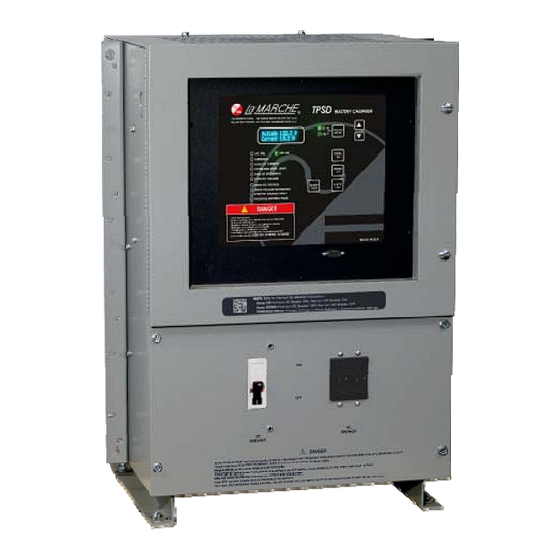
TPSD
Filtered Battery Charger / Power Supply /
Battery Eliminator
106 Bradrock Dr. Des Plaines 60018-1967
Tel: 847 299 1188
Fax: 847 299 3061
Installation and Operation Manual
CPN 127775
Instruction Drawing Number: P25-LTPSD-2
Revision A02
Rev. Date: 12/16
ECN: 21183-2
Advertisement
Table of Contents
Troubleshooting

Subscribe to Our Youtube Channel
Related Manuals for La Marche TPSD

Summary of Contents for La Marche TPSD
- Page 1 La Marche Manufacturing Company | www.lamarchemfg.com TPSD Filtered Battery Charger / Power Supply / Battery Eliminator Installation and Operation Manual 106 Bradrock Dr. Des Plaines 60018-1967 Instruction Drawing Number: P25-LTPSD-2 Tel: 847 299 1188 Fax: 847 299 3061 CPN 127775 Revision A02 Rev.
-
Page 2: Important Safety Instructions
Important Safety Instructions Before using this equipment read all manuals and other documents related to this unit and other equipment connected to this unit. Always have a copy of a units manual on file nearby, in a safe place; if a replacement copy of a manual is needed it can be found at the www.lamarchemfg.com. -
Page 3: Unit Location
In the unlikely event of internal damage, please inform the carrier and contact La Marche for advice on the risk due to any damage before installing the product. Verify that you have all the necessary parts per your order for proper assembly. -
Page 4: Table Of Contents
Installation ............................3 Mounting the TPSD ........................3 2.1.1 Wall-Mounting the TPSD (4B, 4 and 9 Cases Only) ..............3 2.1.2 Floor-Mounting the TPSD (All Cases) ..................5 2.1.3 Rack-Mounting the TPSD ......................6 ... - Page 5 Checking Capacitors ....................... 31 Appendix A: TPSD Specifications ....................... 32 Appendix B: TPSD Current Draw and Feeder Breaker Sizes ................33 Appendix C: TPSD Heat Losses ......................... 35 Appendix D: Field Installable Accessory Kits ....................36 ...
-
Page 6: Table Of Figures
Table 2 - Case Type and Weight (Three Phase, 25-200 ADC) ................. 2 Table 3 - Available mounting methods for each of the TPSD case sizes ............3 Table 4 - Available Rack Mount Configurations ..................... 6 ... -
Page 7: Model Scope/General Description
Form “C” contacts. The TPSD is offered with DC output voltages of 24, 48 or 130VDC with output currents from 6 to 200 Amps. These chargers may be powered with 120, 208, 240, or 480VAC. -
Page 8: Equipment Handling
Storing the TPSD If the TPSD is to be stored for more than a few days after delivery, it should be stored within its shipping container. The location chosen for storage should be within an ambient temperature of -40 to 185° F (-40 to 85°... - Page 9 Ampere Rating Output Frequency Voltage 25 ADC 30 ADC 35 ADC 50 ADC 75 ADC 100 ADC 125 ADC 150 ADC 200 ADC 72 Case 72 Case 72 Case 72 Case 24 VDC 60 Hz 400 lbs 475 lbs 530 lbs 600 lbs (181.4 kg) (215.5 kg)
-
Page 10: Installation
Verify the method of mounting and the weight of the TPSD, using Tables 1, 2, and 3. The location chosen for the charger should be within an ambient temperature range of 32 to 122˚F (0 to 50˚C) with a non-condensing relative humidity no... -
Page 11: Wall-Mounting The Tpsd (4B, 4 And 9 Cases Only)
2.1.1 Wall-Mounting the TPSD (4B, 4 and 9 Cases Only) The 4B, 4 and 9 cases of the TPSD are shipped from the factory with the necessary brackets installed for wall- mounting (The same bracket is used for rear mounting on a relay rack, 4B and 4 – 19/23” rack, 9 – 23/30”... -
Page 12: Floor-Mounting The Tpsd (All Cases)
44 cases include the height of the bracket in their overall height Floor-Mounting Procedure To floor-mount the TPSD, install four bolts into the floor. Place the TPSD on the bolts, add appropriate mounting hardware, and tighten securely. The figure below shows the footprint and the bolt size of each TPSD case style. -
Page 13: Rack-Mounting The Tpsd
2.1.3 Rack-Mounting the TPSD The TPSD can be installed in most relay racks with standard EIA hole spacing. If a relay rack is needed they are available for purchase from La Marche. The 4B, 4 and 9 cases are shipped from the factory with the necessary (The same bracket is used for wall mounting). -
Page 14: Changing Transformer Taps
NOTE: The TPSD is wired at the factory for 240 VAC, except on special request... Before changing the PT taps, be sure that AC supply and DC loads to the TPSD are turned off and locked out. Verify that no voltage is present by using a voltmeter at all input and output terminals. Turning off the AC and... -
Page 15: Changing Transformer Taps Procedure
2.2.1 Changing Transformer Taps Procedure Before beginning any work inside the charger enclosure ensure that all incoming AC supply and DC load wires are de-energized. Verify that no voltage is present inside the case by using a voltmeter at all input and output terminals. -
Page 16: Making The Ac Input Connections
Making the AC Input Connections Before making any connections to the TPSD ensure that the AC Power is off at the main breaker box and that both of the unit’s breakers are off. Check that the source voltage and frequency matches the voltage and frequency listed on the charger nameplate. -
Page 17: Making The Dc Output Connections
Making the DC Output Connections Before making any of DC output connections make sure you have read and fully understand the DC Connection Procedure below. Select proper size for the DC wiring from the wire size table on the previous page. If the distance between the unit’s DC output and the DC load exceeds 10 feet, use the Power Cable Guide below to minimize the voltage drop across the wire distance. -
Page 18: Alarm Connections
2.5.1 Alarm Connection Procedure Before making any connections to the TPSD ensure that the AC Power is off at the main breaker box and that both of the unit’s breakers are off. Verify that no voltage is present by using a voltmeter at all input and output terminals. -
Page 19: Figure 10 - Example Connections (Customer Provided Equipment)
Example of connecting a “Summary” alarm Before making any connections to the TPSD ensure that the AC Power is off at the main breaker box and that both of the unit’s breakers are off. Verify that no voltage is present by using a voltmeter at all input and output terminals. -
Page 20: Understanding The Alarms
2.5.2 Understanding the Alarms Each alarm indication relay in the TPSD is designed as fail-safe. This means that under a complete system malfunction with all alarm relays de-energized, each alarm will indicate its correct state. Table 9 shows what state each alarm relay is in under normal running conditions of the charger, no alarms are present. -
Page 21: Table 10 – Factory Setting For Alarm Time Delays
AC POWER FAIL ALARM will trigger immediately when the AC power to the unit is lost, green “AC” LED will turn off. The alarm will automatically reset when AC power is restored to the unit. When AC power is lost the front panel display and indicators will remain powered by the connected batteries. -
Page 22: Installing External Temperature Compensation (Option 11W/11Y)
External Probe Connection Procedure 1. Before making any connections to the TPSD ensure that the AC Power is off at the main breaker box and that both of the unit’s breakers are off. Verify that no voltage is present by using a voltmeter at all input and output terminals. -
Page 23: Enabling Load Sharing
Load Sharing Procedure Before making any connections to the TPSD ensure that the AC Power is off at the main breaker box and that both of the units’ breakers are off. Verify that no voltage is present by using a voltmeter at all input and output terminals. -
Page 24: Enabling/Disabling Ground Detection
Ground Detection Procedure Before making any changes to the TPSD ensure that the AC Power is off at the main breaker box and that both of the units’ breakers are off. To enable or disable ground detection, first locate the S2A-341S card inside the unit. -
Page 25: Dnp 3 / Modbus Scada Interface (Option 21P/21Q)
The optional DNP 3/ Modbus Scada Interface Communication Card, allows the customer to remotely connect to the TPSD battery charger. The card is equipped with four methods of communication; DNP 3.0, Modbus ASCII, Modbus RTU and Modbus TCP. There are three different ports for connection to the communication card. The three port types for connection are: RS232, RS485 and TCP (Ethernet). -
Page 26: Operation
Factory Settings The factory settings of the TPSD are based on the customer order, unless otherwise specified all units are set at the factory with the following settings. Float Voltage: 2.17 V/C for LA and 2.25 V/C for VRLA... -
Page 27: Digital Control Board
The TPSD is available with an LCD or VFD digital control board as Options 550 or 551 respectively. These options replace the LED analog control board that is standard to the TPSD. The digital control board is a more attractive and user friendly option, with many additional features over the standard LED analog control board. -
Page 28: Selecting The Charging Mode
The TPSD has two different settings for DC output voltage, float mode and equalize mode. Float charging mode is used for all normal battery charging needs, in the case of the TPSD the float mode can also be used for battery elimination (directly powering the DC load from the TPSD). -
Page 29: Adjusting Parameters
Refer to page # for TPSD control menu structure flow chart. 3.4.1 Settings Menu In the Settings Menu the customer can access and change various parameters used by the TPSD. To access the Settings Menu, press the MENU button, select “Settings Menu” and press the ENTER button. - Page 30 The approximate adjustable range is as follows: 2.15 – 2.50 V/C (LA) (VRLA) 1.40 – 1.70 V/C (NC) 3.4.1.2. Equalize Timer Settings The Equalize Timer Settings submenu provides access to the change the Equalize Timer Mode, and Equalize Timer Hours. Equalize Timer Mode The equalize timer mode determines when the charger will go into an equalize charging cycle.
- Page 31 Alarm 150.0 V Alarm threshold defaults are based on the charger output. The alarm threshold values shown above are not representative of the default values for any specific TPSD charger. Alarm Operation The Alarm Operation setting defines if the alarms relays latch. If any alarm contacts are set to latch, the alarm will not clear until the ALARM RESET button is pressed, even if the alarm condition returns to normal.
-
Page 32: Communications Settings
3.4.1.5. Communications Settings The communication settings menu changes depending on the type of communication protocol used in the unit. For details on connection instructions as well as operation instructions refer to the Scada Interface instruction manual included with the unit. 3.4.1.5.1 Units with DNP 3.0 Communication Protocol (Option 21P). -
Page 33: Test Menu
3.5.1 Test LEDs The Test LEDs menu allows the customer to run a basic lamp test on the TPSD. After selecting this menu press the “ENTER” button to light all of the LEDs on the display membrane. To end the LED test press back. - Page 34 TPSD Control Menu Structure Settings Menu Float / Equalize Voltage Float Voltage → Equalize Voltage Equalize Timer Settings Timer Mode → Timer Hours → Alarm Settings Summary Alarm Selects Low Current, AC Fail, Yes / No → → → Ground Detection Alarm Delays Overload, End of Dis.
-
Page 35: Service
Before working inside the TPSD ensure that the AC Power is off at the main breaker box and that both of the unit’s breakers are off. Verify that no voltage is present by using a voltmeter at all input and output terminals. -
Page 36: Troubleshooting Procedure
Troubleshooting Procedure Troubleshooting should be performed only by trained service personnel or experienced electricians. Before setting up any complicated testing or jumping to any conclusions, give the unit a general inspection. Check the following: 1. Check DC output cables, connections, battery type, and number of cells against the unit’s rating. 2. -
Page 37: Symptoms & Causes
Symptoms & Causes 4.3.1 AC Breaker Trips Possible Cause: 1. Wrong AC input voltage. 2. The AC input taps on power transformer set incorrectly. (See section 2.2.1 Changing Transformer Taps procedure) 3. An AC to DC short or AC or DC short to ground. (See section 4.3.5 Ground and Short Circuit Test) 4. -
Page 38: Ground And Short Circuit Test
4.3.5 Ground and Short Circuit Test. A simple ohmmeter check can be performed to check the unit for a short to ground, primary to secondary breakdown, AC-DC short, or DC ground. Before installation of a new unit, the above checks should be made before installing. -
Page 39: Appendix A: Tpsd Specifications
± 0.5% from no load to full load over the specified input voltage, frequency and ambient Regulation temperature range. Load Sharing When connected identical TPSD units are forced to share the load equally (within ± 5%). Meters Digital Meter Display Optional second Digital Meter Display (DC Volts Only) -
Page 40: Appendix B: Tpsd Current Draw And Feeder Breaker Sizes
Appendix B: TPSD Current Draw and Feeder Breaker Sizes Single Phase 60 Hz 50 Hz Model AC Current Draw (Recommended Feeder AC Supply Breaker) Number Amps ABD1 BLD1 120V 120/240/208V 240/220/208V 480V 240/220V TPSD-6-24V 2 (5) TPSD-12-24V 4 (10) TPSD-20-24V 6.7/3.4/3.9 (10/5/5) - Page 41 Three Phase 60 Hz 50 Hz Model Number AC Current Draw (Recommended Feeder AC Supply Breaker) Amps BD3 (240/208V) C3 (480V) 5G3 (380V) TPSD-75-24V 6.3/7.3 (10/10) TPSD-100-24V 8.5/9.8 (15/15) TPSD-150-24V 13/15 (20/20) 6.3 (15) TPSD-200-24V 17/20 (25/25) 8.5 (15) TPSD-50-48V 8.5/9.8 (15/15)
-
Page 42: Appendix C: Tpsd Heat Losses
Appendix C: TPSD Heat Losses (Based on 85% efficiency for single phase units, 90% efficiency for three phase units at 240V nominal input and rated load) Single Phase AC DRAW WATTS IN WATTS OUT WATTS LOST BTU/HR 1071 1529 1300... -
Page 43: Appendix D: Field Installable Accessory Kits
Appendix D: Field Installable Accessory Kits La Marche offers multiple accessory kits that are available for purchase separately from the TPSD units. These accessories are installable in the field. Not all accessory kits will be installable in all enclosures. –... -
Page 44: Appendix E: Manufacturer's Warranty
(4) years of this five (5) year warranty period, the warranty covers parts replacement only, and no labor or other services are provided by La Marche, nor is La Marche obligated to reimburse the owner or any other person for work performed. -
Page 45: Appendix F: Manufacturer's Extended Parts Warranty
Should minor adjustments be required, the local La Marche sales representative should be contacted to provide this service only. All sales are final. Only standard La Marche units will be considered for return. A 25% restocking fee is charged when return is factory authorized. Special units are not returnable. -
Page 46: Appendix G: Document Control And Revision History
Appendix G: Document Control and Revision History Part Number: 127775 Instruction Number: P25-LTPSD-2 Issue ECN: 20117 – 10/13 20567-9/14 20877–7/15 21183-2 – 12/16...
Need help?
Do you have a question about the TPSD and is the answer not in the manual?
Questions and answers
what causes the control board kept blowing fuse 1/2amp
@Alvin Clarke what causes the control board kept blowing fuse 1/2amp