Table of Contents
Advertisement
Quick Links
Advertisement
Table of Contents

Related Manuals for METREL EurotestXDs MI 3154


Summary of Contents for METREL EurotestXDs MI 3154
- Page 1 EurotestXDs MI 3154 Instruction manual Version 1.1.2, Code no. 20 753 203...
- Page 2 Mark on your equipment certifies that it meets requirements of all subjected EU regulations. Hereby, Metrel d.d. declares that the MI 3154 is in compliance with subjected EU directive. The full text of the EU declaration of conformity is available at the https://www.metrel.si/DoC.
- Page 3 Please note that LCD screenshots in this document may differ from the actual instrument screens in details due to firmware variations and modifications. Metrel reserve the right to make technical modifications without notice as part of the further development of the product.
-
Page 4: Table Of Contents
MI 3154 EurotestXDs Table of Contents Table of Contents General description ......................8 Warnings and notes ....................8 1.1.1 Safety warnings ....................... 8 1.1.2 Markings on the instrument ..................9 1.1.3 Warnings related to safety of batteries ..............9 1.1.4 Warnings related to safety of measurement functions ..........9 1.1.5 Notes related to measurement functions ............... - Page 5 MI 3154 EurotestXDs Table of Contents 4.8.2 Workspace Manager main menu ................50 4.8.3 Operations with Workspaces ................. 51 4.8.4 Operations with Exports ..................51 4.8.5 Adding a new Workspace ..................53 4.8.6 Opening a Workspace ................... 54 4.8.7 Deleting a Workspace / Export ................54 4.8.8 Importing a Workspace ..................
- Page 6 MI 3154 EurotestXDs Table of Contents 7.20 ELR Combination Time Test (MI 3144) ..............148 7.21 EVSE Diagnostic Test (A 1632) ................150 Earth – Earth resistance (3-wire test) ..............153 7.22 Earth 2 clamp – Contactless earthing resistance measurement 7.23 (with two current clamps) ..................
- Page 7 MI 3154 EurotestXDs Table of Contents 12.4 RCD testing ......................214 12.4.1 General data ....................214 RCD Uc – Contact voltage ................215 12.4.2 RCD t – Trip-out time ..................215 12.4.3 RCD I – Trip-out current .................. 215 12.4.4 12.4.5 RCD Auto ......................
-
Page 8: General Description
MI 3154 EurotestXDs General description 1 General description Warnings and notes Read before use 1.1.1 Safety warnings In order to reach high level of operator safety while carrying out various measurements using the EurotestXDs instrument, as well as to keep the test equipment undamaged, it is necessary to consider the following general warnings: ... -
Page 9: Markings On The Instrument
MI 3154 EurotestXDs General description Hazardous voltages exist inside the instrument. Disconnect all test leads, remove the power supply cable and switch off the instrument before removing battery /fuse compartment cover. Do not connect any voltage source on C1 inputs. It is intended only for connection of current clamps. -
Page 10: Notes Related To Measurement Functions
MI 3154 EurotestXDs General description 1.1.5 Notes related to measurement functions Insulation resistance (R iso, R iso – all) The measuring range is decreased if using Tip commander A 1401. If a voltage of higher than 30 V (AC or DC) is detected between test terminals, the measurement will not be performed. - Page 11 MI 3154 EurotestXDs General description The Zs rcd function takes longer to complete but offers much better accuracy of fault loop resistance (in comparison to the R sub-result in Contact voltage function). Auto test is finished without x5 tests in case of testing the RCD types A, F, B and B+ with rated residual currents of I = 300 mA, 500 mA, and 1000 mA or testing the RCD type AC with rated residual current of I...
- Page 12 METREL assumes no responsibility for any Auto Sequence® by any means. It is the user’s responsibility, to check adequacy for the purpose of use of the selected Auto Sequence®.
-
Page 13: Testing Potential On Pe Terminal
MI 3154 EurotestXDs General description Testing potential on PE terminal In certain instance faults on the installation's PE wire or any other accessible metal bonding parts can become exposed to live voltage. This is a very dangerous situation since the parts connected to the earthing system are considered to be free of potential. - Page 14 MI 3154 EurotestXDs General description Test procedure Connect test cable to the instrument. Connect test leads to the object under test, see Figure 1.1 and Figure 1.2. Touch test probe for at least 1 second. If PE terminal is connected to phase voltage the warning message is displayed, display is yellow coloured, instrument buzzer is activated and further measurements are disabled: RCD tests, Z loop, Zs rcd, Z auto, AUTO TT, AUTO TN, AUTO TN (rcd) and Auto Sequences®.
-
Page 15: Battery And Charging Of Li-Ion Battery Pack
MI 3154 EurotestXDs General description Battery and charging of Li-ion battery pack The instrument is designed to be powered by rechargeable Li-ion battery pack. The LCD contains an indication of battery condition (upper right section of LCD). In case the battery is too weak the instrument indicates this as shown in Figure 1.3. -
Page 16: Precharge
MI 3154 EurotestXDs General description Typical charging profile which is also used in this instrument is shown in Figure 1.6. Current Regulation LOWV CH/8 Precharge Fastcharge Safety Time Time Figure 1.6: Typical charging profile where: ........Battery charging voltage ........Precharge threshold voltage LOWV ........ - Page 17 MI 3154 EurotestXDs General description Typical charging time is 3 hours (Battery type: 18650T22A2S2P) in the temperature range of 5°C to 60°C. ch/8 Figure 1.9: Typical charging current vs temperature profile where: ... Cold temperature threshold (typ. -15°C) ..Cool temperature threshold (typ. 0°C) COOL ..
-
Page 18: Li - Ion Battery Pack Guidelines
MI 3154 EurotestXDs General description Li – ion battery pack guidelines 1.3.2 Li – ion rechargeable battery pack requires routine maintenance and care in their use and handling. Read and follow the guidelines in this Instruction manual to safely use Li – ion battery pack and achieve the maximum battery life cycles. -
Page 19: Standards Applied
MI 3154 EurotestXDs General description Standards applied The EurotestXDs instruments are manufactured and tested in accordance with the following regulations: Electromagnetic compatibility (EMC) EN 61326-1 Electrical equipment for measurement, control and laboratory use – EMC requirements – Part 1: General requirements EN 61326-2-2 Electrical equipment for measurement, control and laboratory use - EMC requirements –... - Page 20 MI 3154 EurotestXDs General description Li – ion battery pack EN 62133-2 Secondary cells and batteries containing alkaline or other non-acid electrolytes – Safety requirements for portable sealed secondary lithium cell, and for batteries made from them, for use in portable applications – Part 2: Lithium systems protection for household and similar uses...
-
Page 21: Instrument Set And Accessories
Li-ion battery pack, 7.2 V, 4400 mAh (Type: 18650T22A2S2P) Power supply adapter 12 V, 3 A (Type: CGSW-1203000) CD includes: PC software Metrel ES Manager Instruction manual “Guide for testing and verification of low voltage installations” handbook ... -
Page 22: Instrument Description
MI 3154 EurotestXDs Instrument description 3 Instrument description Front panel Figure 3.1: Front panel 4,3“ COLOR TFT DISPLAY WITH TOUCH SCREEN SAVE key Stores actual measurement result(s) CURSOR keys Navigate in menus RUN key Start / stop selected measurement. Enter selected menu or option. View available values for selected parameter / limit. -
Page 23: Connector Panel
MI 3154 EurotestXDs Instrument description Connector panel Figure 3.2: Connector panel Test connector L/L1 pin N/L2 pin PE/L3 pin S pin – (Not used) Protection cover Protection cover – PS/2 communication port Charger socket USB communication port Communication with PC USB (2.0) port PS/2 communication port Communication with PC RS232 serial port Connection to optional measuring adapters... -
Page 24: Back Side
MI 3154 EurotestXDs Instrument description Back side Figure 3.3: Back view Battery / fuse compartment cover Fixing screws for battery / fuse compartment cover Back panel information label Figure 3.4: Battery and fuse compartment Type: 18650T22A2S2P 1 Li-ion battery pack Type: 18650T22A2S4P (optional) 2 Fuse F1 M 315 mA / 250 V... - Page 25 MI 3154 EurotestXDs Instrument description 4 SD card slot Figure 3.5: Bottom view Neck belt openings Stand for desktop use Bottom information label Serial number label...
-
Page 26: Carrying The Instrument
MI 3154 EurotestXDs Instrument description Carrying the instrument With the neck-carrying belt supplied in standard set, various possibilities of carrying the instrument are available. Operator can choose appropriate one on basis of his operation, see the following examples: The instrument hangs around operator’s neck only –... - Page 27 MI 3154 EurotestXDs Instrument description Figure 3.7: Alternative method Please perform a periodical check of the attachment.
-
Page 28: Instrument Operation
MI 3154 EurotestXDs Instrument operation 4 Instrument operation The EurotestXDs instrument can be manipulated via a keypad or touch screen. General meaning of keys Cursor keys are used to: select appropriate option. Run key is used to: confirm selected option; ... -
Page 29: General Meaning Of Touch Gestures
MI 3154 EurotestXDs Instrument operation General meaning of touch gestures Tap (briefly touch surface with fingertip) is used to: select appropriate option; confirm selected option; start and stop measurements. Swipe (press, move, lift) up / down is used to: ... -
Page 30: Virtual Keyboard
MI 3154 EurotestXDs Instrument operation Virtual keyboard Figure 4.1: Virtual keyboard Toggle case between lowercase and uppercase. Active only when alphabetic characters keyboard layout selected. Backspace Clears last character or all characters if selected. (If held for 2 s, all characters are selected). Enter confirms new text. -
Page 31: Display And Sound
MI 3154 EurotestXDs Instrument operation Display and sound 4.4.1 Terminal voltage monitor The terminal voltage monitor displays on-line the voltages on the test terminals and information about active test terminals in the a.c. installation measuring mode. Online voltages are displayed together with test terminal indication. All three test terminals are used for selected measurement. -
Page 32: Bluetooth
MI 3154 EurotestXDs Instrument operation Charging finished. 4.4.3 Bluetooth Bluetooth communication inactive. Bluetooth communication active. 4.4.4 Measurement actions and messages Conditions on the input terminals allow starting the measurement. Consider other displayed warnings and messages. Conditions on the input terminals do not allow starting the measurement. Consider displayed warnings and messages. - Page 33 MI 3154 EurotestXDs Instrument operation Measurement is running, consider displayed warnings. RCD tripped-out during the measurement (in RCD functions). Instrument is overheated. The measurement is prohibited until the temperature decreases under the allowed limit. High electrical noise was detected during measurement. Results may be impaired.
-
Page 34: Result Indication
MI 3154 EurotestXDs Instrument operation Single fault condition in IT system. Fuse F1 is broken. 4.4.5 Result indication Measurement result is inside pre-set limits (PASS). Measurement result is out of pre-set limits (FAIL). Measurement is aborted. Consider displayed warnings and messages. RCD t and RCD I measurements will only be performed if the contact voltage in the pre-test at nominal differential current is lower than the set contact voltage limit! -
Page 35: Instruments Main Menu
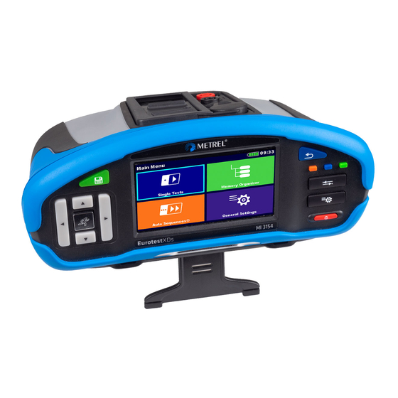
MI 3154 EurotestXDs Instrument operation Instruments main menu From the Main menu different main operation menus can be selected. Figure 4.2: Main menu Options Single Tests Menu with single tests, see chapter 6 Single tests. Auto Sequences Menu with customized test sequences, see chapter 8 Auto Sequences®. -
Page 36: General Settings
MI 3154 EurotestXDs Instrument operation General Settings In the General settings menu general parameters and settings of the instrument can be viewed or set. Figure 4.3: General settings menu Options Language Instrument language selection. Power Save Brightness of LCD, enabling/disabling Bluetooth communication. Date /Time Instruments Date and time. -
Page 37: Language
MI 3154 EurotestXDs Instrument operation About Instrument info. 4.6.1 Language In this menu the language of the instrument can be set. Figure 4.4: Language menu 4.6.2 Power Save In this menu different options for decreasing power consumption can be set. Figure 4.5: Power save menu Brightness Setting level of LCD brightness level. -
Page 38: Date And Time
MI 3154 EurotestXDs Instrument operation 4.6.3 Date and time In this menu date and time of the instrument can be set. Figure 4.6: Setting date and time Note: If the batteries are removed the set date and time will be lost. 4.6.4 Workspace manager Refer to chapter 4.8 Workspace Manager for more information. - Page 39 MI 3154 EurotestXDs Instrument operation Figure 4.7: Sign in menu Options User signing in The user should be selected first. The last used user is displayed in the first row. Sign in with selected user name. Enter the password and confirm. The user password consists of up to 4-digit number.
- Page 40 MI 3154 EurotestXDs Instrument operation 4.6.5.2 Changing user password, signing out Figure 4.8: User profile menu Options Signs out the set user. Enters procedure for changing the user’s password. The user can change its password. The actual password must be entered first followed by the new password.
- Page 41 MI 3154 EurotestXDs Instrument operation The account manager password must be entered and confirmed first. The default password is ADMIN. Field for setting if signing in is required to work with the instrument. Field for setting if signing is required once or at each power on of the instrument.
- Page 42 MI 3154 EurotestXDs Instrument operation In the Add New window the name and initial password of the new user account are to be set. ‘Add’ confirms the new user data. Changes password of the selected user account. Deletes all user accounts. Deletes the selected user account.
-
Page 43: Profiles
MI 3154 EurotestXDs Instrument operation Blackbox password is changed. 4.6.6 Profiles Refer to chapter 4.7 Instrument profiles for more information. 4.6.7 Settings In this menu different general parameters can be set. Figure 4.11: Settings menu Available selection Description Touch screen [ON, OFF] Enables / disables operation with touch screen. - Page 44 [Custom, 12 V, 25 V, Contact voltage limit. 50 V] 4.6.7.1 Adapters Settings menu provide selection and configuration of Metrel measuring adapters to perform supported tests and measurements. See Appendix D for details on available Metrel adapters and supported tests.
- Page 45 MI 3154 EurotestXDs Instrument operation Available selection Description Adapter type [none, selected adapter] Selection from list of available adapters. Port [RS232, Bluetooth] Sets communication port of selected measuring adapter. See chapter 9.3 Communication with adapters for more details. Bluetooth Name of selected adapter After searching is finished, list of all device name available Bluetooth devices is presented.
- Page 46 MI 3154 EurotestXDs Instrument operation 500 ms 200 ms 150 ms > 30 > 999 ms 130 ms 60 ms 50 ms Minimum non-actuating time Table 4.4: Trip-out times according to AS/NZS 3017 ½I Standard 2I 5I N N ...
-
Page 47: Devices
MI 3154 EurotestXDs Instrument operation 30 mA 60 mA 150 mA Standard (1 I (2 I (5 I N N N IEC 62752 < 300 ms < 150 ms < 40 ms Table 4.8: Break times for a.c. residual currents IEC 62752: Table 2 –... -
Page 48: Initial Settings
MI 3154 EurotestXDs Instrument operation 4.6.9 Initial Settings In this menu the instrument settings, measurement parameters and limits can be set to initial (factory) values. Figure 4.13: Initial settings menu Warning! Following customized settings will be lost when setting the instruments to initial settings: ... -
Page 49: Instrument Profiles
MI 3154 EurotestXDs Instrument operation Instrument profiles In this menu the instrument profile can be selected from the available ones. This menu is visible only if more than one profile is available. Figure 4.15: Instrument profiles menu The instrument uses different specific system and measuring settings in regard to the scope of work or country it is used. -
Page 50: Workspace Manager
Workspaces are stored on SD card on directory WORKSPACES, while Exports are stored on directory EXPORTS. Export files can be read by METREL applications that run on other devices. Exports are suitable for making backups of important works. To work on the instrument an Export should be imported first from the list of Exports and converted to a Workspace. -
Page 51: Operations With Workspaces
MI 3154 EurotestXDs Instrument operation 4.8.3 Operations with Workspaces Only one Workspace can be opened in the instrument at the same time. The Workspace selected in the Workspace Manager will be opened in the Memory Organizer. Figure 4.17: Workspaces menu Options Marks the opened Workspace in Memory Organizer. - Page 52 MI 3154 EurotestXDs Instrument operation Options Deletes the selected Export. Refer to chapter 4.8.7 Deleting a Workspace / Export for more information. Imports a new Workspace from Export. Refer to 4.8.8 Importing a Workspace for more information. Opens more options in control panel / expands column.
-
Page 53: Adding A New Workspace
MI 3154 EurotestXDs Instrument operation 4.8.5 Adding a new Workspace Procedure New Workspaces can be added from the Workspace Manager screen. Enters option for adding a new Workspace. Keypad for entering name of a new Workspace is displayed after selecting New. -
Page 54: Opening A Workspace
MI 3154 EurotestXDs Instrument operation 4.8.6 Opening a Workspace Procedure Workspace can be selected from a list in Workspace manager screen. Opens a Workspace in Workspace manager. The opened Workspace is marked with a blue dot. The previously opened Workspace will close automatically. -
Page 55: Importing A Workspace
MI 3154 EurotestXDs Instrument operation Workspace / Export is deleted from the Workspace / Export list. 4.8.8 Importing a Workspace Select an Export file to be imported from Workspace manager Export list. Enters option Import. Before the import of the selected Export file the user is asked for confirmation. -
Page 56: Exporting A Workspace
MI 3154 EurotestXDs Instrument operation 4.8.9 Exporting a Workspace Select a Workspace from Workspace manager list to be exported to an Export file. Enters option Export. Before exporting the selected Workspace the user is asked for confirmation. Workspace is exported to Export file and is added to the list of Exports. -
Page 57: Memory Organizer
MI 3154 EurotestXDs Memory Organizer 5 Memory Organizer Memory Organizer is a tool for storing and working with test data. Memory Organizer menu The data is organized in a tree structure with Structure objects and Measurements. MI 3154 – EurotestXDs instrument has a multi-level structure. The hierarchy of Structure objects in the tree is shown on Figure 5.1. -
Page 58: Structure Objects
MI 3154 EurotestXDs Memory Organizer Statuses of Single tests passed finished single test with test results failed finished single test with test results finished single test with test results and no status empty single test without test results Overall statuses of Auto Sequence® At least one single test in the Auto sequence... - Page 59 MI 3154 EurotestXDs Memory Organizer Options There are no measurement results under selected structure object. Measurements should be made. One or more measurement result(s) under selected structure object has failed. Not all measurements under selected structure object have been made yet. All measurements under selected structure object are completed but one or more...
-
Page 60: Selecting An Active Workspace In Memory Organizer
MI 3154 EurotestXDs Memory Organizer 5.1.3 Selecting an active Workspace in Memory Organizer Memory Organizer and Workspace Manager are interconnected so an active Workspace can be selected also in the Memory Organizer menu. Procedure Press the active Workspace in Memory ... -
Page 61: Adding Nodes In Memory Organizer
MI 3154 EurotestXDs Memory Organizer 5.1.4 Adding Nodes in Memory Organizer Structural Elements (Nodes) are used to ease organization of data in the Memory Organizer. One Node is a must; others are optional and can be created or deleted freely. Procedure Press the active Workspace in Memory ... -
Page 62: Operations In Tree Menu
MI 3154 EurotestXDs Memory Organizer 5.1.5 Operations in Tree menu In the Memory organizer different actions can be taken with help of the control panel at the right side of the display. Possible actions depend on the selected element in the organizer. 5.1.5.1 Operations on measurements (finished or empty measurements) Figure 5.4: A measurement is selected in the Tree menu... - Page 63 MI 3154 EurotestXDs Memory Organizer The instrument displays comment attached to the selected measurement or opens keypad for entering a new comment. Deletes a measurement. Selected Measurement can be deleted. User is asked for confirmation before the deleting. Refer to chapter 5.1.5.13 Delete a measurement for more information. 5.1.5.2 Operations on Structure objects The structure object must be selected first.
- Page 64 MI 3154 EurotestXDs Memory Organizer Selected Structure object can be copied to same level in structure tree (clone). Refer to chapter 5.1.5.6 Clone a Structure object for more information. Copies & Paste a Structure object. Selected Structure object can be copied and pasted to any allowed location in structure tree.
- Page 65 MI 3154 EurotestXDs Memory Organizer 5.1.5.3 View / Edit parameters and attachments of a Structure object The parameters and their content are displayed in this menu. To edit the selected parameter, tap on it or press the key to enter menu for editing parameters. Procedure ...
- Page 66 MI 3154 EurotestXDs Memory Organizer Attachments The name of attachment can be seen. Operation with attachments is not supported in the instrument. Select Comments in Control panel. View or edit comments Complete comment (if exists) attached to the structure object can be seen on this screen.
- Page 67 MI 3154 EurotestXDs Memory Organizer 5.1.5.4 Add a new Structure Object This menu is intended to add new structure objects in the tree menu. A new structure object can be selected and then added in the tree menu. Procedure Default initial structure.
- Page 68 MI 3154 EurotestXDs Memory Organizer New object added.
- Page 69 MI 3154 EurotestXDs Memory Organizer 5.1.5.5 Add a new measurement In this menu new empty measurements can be set and then added in the structure tree. The type of measurement, measurement function and its parameters are first selected and then added under the selected Structure object.
- Page 70 MI 3154 EurotestXDs Memory Organizer Select parameter and modify it as described earlier. Refer to chapter 6.1.2 Setting parameters, limits and comments of single tests for more information. Adds the measurement under the selected Structure object in the tree menu.
- Page 71 MI 3154 EurotestXDs Memory Organizer 5.1.5.6 Clone a Structure object In this menu selected structure object can be copied (cloned) to same level in the structure tree. Cloned structure object has the same name as the original. Procedure Select the structure object to be cloned. ...
- Page 72 MI 3154 EurotestXDs Memory Organizer 5.1.5.7 Clone a measurement By using this function, a selected empty or finished measurement can be copied (cloned) as an empty measurement to the same level in the structure tree. Parameters and limits of new measurement are the same as they are set in original measurement.
- Page 73 MI 3154 EurotestXDs Memory Organizer 5.1.5.8 Copy & Paste a Structure object In this menu selected Structure object can be copied and pasted to any allowed location in the structure tree. Procedure Select the structure object to be copied. ...
- Page 74 MI 3154 EurotestXDs Memory Organizer The new structure object is displayed. Note The Paste command can be executed one or more times. 5.1.5.9 Cloning and Pasting sub-elements of selected structure object When structure object is selected to be cloned, or copied & pasted, additional selection of its sub-elements is needed.
- Page 75 MI 3154 EurotestXDs Memory Organizer 5.1.5.10 Copy & Paste a measurement In this menu selected measurement can be copied as an empty measurement to any allowed location in the structure tree. Selected measurement can be copied multiple times to different locations in the structure tree.
- Page 76 MI 3154 EurotestXDs Memory Organizer 5.1.5.11 Cut & Paste a Structure object with sub-items In this menu selected Structure object with sub-items (sub-structures and measurements) can be cut and pasted (moved) to any allowed location in the structure tree. Procedure ...
- Page 77 MI 3154 EurotestXDs Memory Organizer 5.1.5.12 Delete a Structure object In this menu selected Structure object can be deleted. Procedure Select the structure object to be deleted. Select Delete in Control panel. A confirmation window will appear. Selected structure object and its sub- elements are removed.
- Page 78 MI 3154 EurotestXDs Memory Organizer 5.1.5.13 Delete a measurement In this menu selected measurement can be deleted from selected location in the tree structure. Procedure Select a measurement to be deleted. Select Delete in Control panel. A confirmation window will appear. Selected measurement is deleted.
- Page 79 MI 3154 EurotestXDs Memory Organizer 5.1.5.14 Rename a Structure object In this menu selected Structure object can be renamed. Procedure Select the structure object to be renamed. Select Rename in Control panel. Virtual keypad will appear on screen. Enter new text and confirm.
- Page 80 MI 3154 EurotestXDs Memory Organizer 5.1.5.15 Recall and Retest selected measurement Procedure Select the measurement to be recalled. Select Recall results in Control panel. Measurement is recalled. Parameters and limits can be viewed but cannot be edited. ...
-
Page 81: Searching In Memory Organizer
MI 3154 EurotestXDs Memory Organizer Parameters and limits can be viewed and edited. Select Run in Control panel to retest the measurement. Results / sub-results after re-run of recalled measurement. Select Save results in Control panel. Retested measurement is saved under same structure object as original one. - Page 82 MI 3154 EurotestXDs Memory Organizer Procedure Search function is available from the active workspace directory line. Use external device for data entry or follow instructions below for instrument search function. Select Search in control panel to open Search setup menu. ...
- Page 83 MI 3154 EurotestXDs Memory Organizer The search can be narrowed on base of test dates / retest dates (from / to). Clears all filters. Searches through the Memory Organizer for objects according to the set filter. The results are shown in the Search results screen presented on Figure 5.7.
- Page 84 MI 3154 EurotestXDs Memory Organizer Views comment. The instrument displays comment attached to the selected Structure object. Renames the selected Structure object. Refer to chapter 5.1.5.14 Rename a Structure object for more information Note: Search result page consist of up to 50 results.
-
Page 85: Single Tests
MI 3154 EurotestXDs Single tests 6 Single tests Single tests can be selected in the main Single tests menu or in Memory organizer main menu and sub-menus. Selection modes In Single test main menu four modes for selecting single tests are available. Options Area Group With help of area groups, it is possible to limit... -
Page 86: Single Test (Measurement) Screens
MI 3154 EurotestXDs Single tests Cross selector This selection mode is the fastest for working with the keypad. Groups of single tests are organized in a row. For the selected group all single tests are displayed and easy accessible with up /down keys. - Page 87 MI 3154 EurotestXDs Single tests Single test screen organization Header line: ESC touch key function name battery status real time clock Bluetooth connection indication Control panel (available options) Parameters (white) and limits (red) Result field: ...
-
Page 88: Setting Parameters, Limits And Comments Of Single Tests
MI 3154 EurotestXDs Single tests 6.1.2 Setting parameters, limits and comments of single tests Procedure Select the test or measurement. The test can be entered from: Single tests menu or Memory organizer menu once the empty measurement was created in selected object structure. -
Page 89: Single Test Start Screen
MI 3154 EurotestXDs Single tests Select parameter or limit value from the list. Note: Touchscreen or keyboard selection methods can be used interchangeably; confirm keyboard selection with Enter comment and confirm with Accepts and set selected parameters, selected limit values and user comments and exits Single Test setting. -
Page 90: Single Test Screen During Test
MI 3154 EurotestXDs Single tests Refer to chapter 6.1.2 Setting parameters, limits and comments of single tests for more information. Enters cross selector to select test or measurement. long on Expands column in control panel. 6.1.4 Single test screen during test Figure 6.3: Single test is running, example of insulation resistance continuous measurement Operations when test is running:... -
Page 91: Single Test Result Screen
MI 3154 EurotestXDs Single tests 6.1.5 Single test result screen Figure 6.4: Single test results screen, example of insulation resistance measurement results Options (after measurement is finished) Starts a new measurement. Starts a new continuous measurement (if applicable long on selected single test). long Saves the result. - Page 92 MI 3154 EurotestXDs Single tests a new measurement will be saved under the selected Structure object. Opens screen for changing parameters and limits. Refer to chapter 6.1.2 Setting parameters, limits and comments of single tests for more information. Adds comment to the measurement. The instrument opens keypad for entering a comment.
-
Page 93: Editing Graphs (Harmonics)
MI 3154 EurotestXDs Single tests 6.1.6 Editing graphs (Harmonics) Figure 6.5: Example of Harmonics measurement results Options for editing graphs (start screen or after measurement is finished) Plot edit Opens control panel for editing graphs. Increase scale factor for y-axis. Decrease scale factor for y-axis. -
Page 94: Single Test (Inspection) Screens
MI 3154 EurotestXDs Single tests 6.1.7 Single test (inspection) screens Visual and Functional inspections can be treated as a special class of tests. Items to be visually or functionally checked are displayed. In addition, on-line statuses and other information are displayed. - Page 95 MI 3154 EurotestXDs Single tests Starts the inspection. Opens help screens. Refer to chapter 6.1.8 Help screens for more information. 6.1.7.2 Single test (Inspection) screen during test Figure 6.8: Inspection screen (during inspection) Options (during test) Selects item. Stops the inspection. Applies a pass to the selected item or group of items.
- Page 96 MI 3154 EurotestXDs Single tests Rules for automatic applying of statuses: The parent item(s) can automatically get a status on base of statuses in child items. the fail status has highest priority. A fail status for any item will result in a fail status in all ...
- Page 97 MI 3154 EurotestXDs Single tests A new measurement will be saved under the selected Structure object. Adds comment to the measurement. The instrument opens keypad for entering a comment. Opens help screens. Refer to chapter 6.1.8 Help screens for more information. 6.1.7.4 Single test (inspection) memory screen Figure 6.10: Inspection memory screen...
-
Page 98: Help Screens
MI 3154 EurotestXDs Single tests 6.1.8 Help screens Help screens contain diagrams for proper connection of the instrument. Figure 6.11: Examples of help screens Options Opens help screen. Goes to previous / next help screen. Back to test / measurement menu. -
Page 99: Recall Single Test Results Screen
MI 3154 EurotestXDs Single tests 6.1.9 Recall single test results screen Figure 6.12: Recalled results of selected measurement, example of insulation resistance recalled results Options Retest Enters starting screen for a new measurement. Refer to chapter 6.1.3 Single test start screen for more information. -
Page 100: Tests And Measurements
MI 3154 EurotestXDs Tests and measurements 7 Tests and measurements See chapter 6.1 Selection modes for instructions on keys and touch screen functionality. Voltage, frequency and phase sequence Figure 7.1: Voltage measurement menu Measurement parameters System Voltage system [-, 1-phase,3-phase] Test Phase to be tested [-, L1, L2, L3] Limit type... - Page 101 MI 3154 EurotestXDs Tests and measurements In case of 1-phase voltage system and limit type set to voltage. In case of 1-phase voltage system and limit type se to %. In case of 3-phase voltage system and limit type set to voltage. In case of 3-phase voltage system and limit type set to %.
- Page 102 MI 3154 EurotestXDs Tests and measurements Measurement procedure Enter the Voltage function. Set test parameters / limits. Connect test cable to the instrument. Connect test leads to object under test (see Figure 7.2 and Figure 7.3). ...
-
Page 103: R Iso - Insulation Resistance
MI 3154 EurotestXDs Tests and measurements Three-phase TN/TT and IT system: voltage between phases L1 and L2 voltage between phases L1 and L3 voltage between phases L2 and L3 Freq frequency Field 3-phase rotation sequence For Pass test result, Field result must be equal to setting of Reference field parameter (1.2.3 or 3.2.1). - Page 104 MI 3154 EurotestXDs Tests and measurements Connection diagrams Figure 7.7: Connections of 3-wire test lead and Tip commander...
-
Page 105: Load Pretest
MI 3154 EurotestXDs Tests and measurements Measurement procedure Enter the R iso function. Set test parameters / limits. Disconnect tested installation from mains supply and discharge installation as required. Connect test cable to the instrument. Connect test leads to object under test (see Figure 7.7). -
Page 106: R Iso All - Insulation Resistance
MI 3154 EurotestXDs Tests and measurements Load pretest terminals Test Type Riso 3-wire test lead and Tip commander measuring terminals function parameter Riso Lx/N Lx/Ly L/PE L-PE Lx/PE N/PE N-PE Riso - all L-N, L-PE, N-PE Table 7.2: Insulation resistance measuring terminals and Load pretest dependency Figure 7.9: Load pretest warning message R iso all –... - Page 107 MI 3154 EurotestXDs Tests and measurements Connection diagrams Figure 7.11: Connection of 3-wire test lead and Tip commander Measurement procedure Enter the R iso - all function. Set test parameters / limits. Disconnect tested installation from mains supply and discharge installation as required.
-
Page 108: Varistor Test
MI 3154 EurotestXDs Tests and measurements Varistor test Measuring principle A voltage ramp starts from 50 V and rises with a slope of 100 V/s. The measurement ends when the defined end voltage is reached or if the test current exceeds the value of 1 mA. Figure 7.13: Varistor test main menu Measurement parameters / limits I lim... -
Page 109: R Low - Resistance Of Earth Connection And Equipotential Bonding
MI 3154 EurotestXDs Tests and measurements After the measurement is finished wait until tested item is fully discharged. Save results (optional). Figure 7.15: Example of Varistor test result Measurement results / sub-results Calculated a.c. breakdown voltage Breakdown voltage Meaning of the Uac voltage Protection devices intended for a.c. - Page 110 MI 3154 EurotestXDs Tests and measurements Output [LPE, LN] Bonding [Rpe, Local] Current [standard, ramp] Max. resistance [Off, Custom, 0.05 Ω ... 20.0 Ω] Limit(R) R low measurement depends on Output parameter setting, see table below. Output Test terminals L and N L and PE Connection diagram Figure 7.17: Connection of 3-wire test lead plus optional Extension lead...
-
Page 111: Continuity - Continuous Resistance Measurement With Low Current
MI 3154 EurotestXDs Tests and measurements Resistance Result at positive test polarity Result at negative test polarity Continuity – Continuous resistance measurement with low current Figure 7.19: Continuity resistance measurement menu Measurement parameters / limits Sound [On*, Off] Max. resistance [Off, Custom, 0.1 Ω ... 20.0 Ω] Limit(R) *Instrument sounds if resistance is lower than the set limit value. -
Page 112: Compensation Of Test Leads Resistance
MI 3154 EurotestXDs Tests and measurements Measurement procedure Enter the Continuity function. Set test parameters / limits. Connect test cable to the instrument. Compensate the test leads resistance if necessary, see section 7.6.1 Compensation of test leads resistance. ... - Page 113 MI 3154 EurotestXDs Tests and measurements Compensation of test leads resistance procedure Enter R low or Continuity function. Connect test cable to the instrument and short all test leads together, see Figure 7.22. Touch the key to compensate leads resistance. Figure 7.23: Result with old and new calibration values...
-
Page 114: Testing Rcds
MI 3154 EurotestXDs Tests and measurements Testing RCDs Various test and measurements are required for verification of RCD(s) in RCD protected installations. Measurements are based on the EN 61557-6 standard. The following measurements and tests (sub-functions) can be performed: Contact voltage, ... -
Page 115: Rcd Uc - Contact Voltage
MI 3154 EurotestXDs Tests and measurements Earthing system Refer to chapter 4.6.7 Settings for more information. Parameter is available only when parameter Use is set to other (for Electrical Vehicle (EV) RCDs/RCMs and Mobile installations (MI) RCDs). Parameter is available only when RCD I or RCD t test is selected and parameter Use is set to ‘other’. - Page 116 MI 3154 EurotestXDs Tests and measurements A, F 21.41.05I N A, F < 30 mA 21.05I N A, F 221.05I N B, B+ 21.05I N B, B+ 221.05I N Table 7.3: Relation between Uc and I Fault Loop resistance is indicative and calculated from Uc result (without additional proportional ��...
-
Page 117: Rcd T - Trip-Out Time
MI 3154 EurotestXDs Tests and measurements RCD t – Trip-out time 7.7.2 Test procedure Enter the RCD t function. Set test parameters / limits. Connect test cable to the instrument. Connect 3-wire test lead or Plug commander to the object under test, see Figure 7.25. - Page 118 MI 3154 EurotestXDs Tests and measurements Test procedure Enter the RCD I function. Set test parameters / limits. Connect test cable to the instrument. Connect 3-wire test lead or Plug commander to the object under test, see Figure 7.25. ...
-
Page 119: Rcd Auto - Rcd Auto Test
MI 3154 EurotestXDs Tests and measurements RCD Auto – RCD Auto test RCD Auto test function performs a complete RCD test (trip-out time at different residual currents, trip-out current and contact voltage) in one set of automatic tests, guided by the instrument. - Page 120 MI 3154 EurotestXDs Tests and measurements Step 1 Step 2 Step 3 Step 4 Step 5 Step 6 Step 7 Step 8...
- Page 121 MI 3154 EurotestXDs Tests and measurements Step 9 Step 10 Step 11 Step 12 Figure 7.29: Individual steps in RCD Auto test, example on testing EV RCD Test results / sub-results t I∆N d.c. x1, (+) Step 1 trip-out time (I=IN d.c., (+) positive polarity) t I∆N d.c.
-
Page 122: Z Loop - Fault Loop Impedance And Prospective Fault Current
MI 3154 EurotestXDs Tests and measurements Z loop – Fault loop impedance and prospective fault current Figure 7.30: Z loop menu Measurement parameters / limits Fuse Type Selection of fuse type [Off, Custom, gG, NV, B, C, D, K] Fuse I Rated current of selected fuse Fuse t Maximum breaking time of selected fuse... - Page 123 MI 3154 EurotestXDs Tests and measurements Start the measurement. Save results (optional). Figure 7.32: Examples of Loop impedance measurement result Measurement results / sub-results Loop impedance Ipsc Prospective fault current Ulpe Voltage L-PE Resistance of loop impedance Reactance of loop impedance Prospective fault current ��...
-
Page 124: Zs Rcd - Fault Loop Impedance And Prospective Fault Current In System With Rcd
MI 3154 EurotestXDs Tests and measurements 7.10 Zs rcd – Fault loop impedance and prospective fault current in system with RCD Zs rcd measurement prevents trip-out of the RCD in systems with the RCD. Figure 7.33: Zs rcd menu Measurement parameters / limits Protection Protection type [TN, TTrcd] Fuse Type... - Page 125 MI 3154 EurotestXDs Tests and measurements Measurement procedure Enter the Zs rcd function. Set test parameters / limits. Connect test cable to the instrument. Connect 3-wire test lead or Plug commander to the object under test, see Figure 7.34. ...
-
Page 126: Z Loop M - High Precision Fault Loop Impedance And Prospective Fault Current
MI 3154 EurotestXDs Tests and measurements 7.11 Z loop m – High precision fault loop impedance and prospective fault current A 1143 MI 3143 or MI 3144 Figure 7.36: Z loop mΩ menu Measurement parameters / limits Fuse Type Selection of fuse type [Off, Custom, gG, NV, B, C, D, K] Fuse I Rated current of selected fuse Fuse t... - Page 127 MI 3154 EurotestXDs Tests and measurements Figure 7.38: Contact voltage measurement – Connection of A 1143 Measurement procedure Connect MI 3154 instrument with A 1143, MI 3143 or MI 3144 Euro Z adapter / instrument via serial RS232 or pair them using Bluetooth communication. See chapter 4.6.7.1 Adapters.
- Page 128 MI 3154 EurotestXDs Tests and measurements Voltage monitor using A 1143: Ulpe Voltage L-PE Freq Frequency Voltage monitor using MI 3143 or MI 3144: Up1p2 Voltage P1-P2 Uc1c2 Voltage C1-C2 Freq Frequency Refer to A 1143 – Euro Z 290 A, MI 3143 – Euro Z 440 V and MI 3144 – Euro Z 800 V Instruction manuals for detailed information.
-
Page 129: Z Line - Line Impedance And Prospective Short-Circuit Current
MI 3154 EurotestXDs Tests and measurements 7.12 Z line – Line impedance and prospective short-circuit current Figure 7.40: Z line measurement menu Measurement parameters / limits Fuse Type Selection of fuse type [Off, Custom, gG, NV, B, C, D, K] Fuse I Rated current of selected fuse Fuse t... - Page 130 MI 3154 EurotestXDs Tests and measurements Measurement procedure Enter the Z line function. Set test parameters / limits. Connect test cable to the instrument. Connect 3-wire test lead or Plug commander to the object under test, see Figure 7.41.
- Page 131 MI 3154 EurotestXDs Tests and measurements The prospective short-circuit currents I and I are calculated as Min2p Min3p Max2p Max3p follows: �� = √ (1.5 × �� + �� �� �� ( L−N ) hot (L−N) (L−N) n(L−N) �� where 0.95;...
-
Page 132: Z Line M - High Precision Line Impedance And Prospective Short-Circuit Current
MI 3154 EurotestXDs Tests and measurements 7.13 Z line m – High precision line impedance and prospective short-circuit current A 1143 MI 3143 or MI 3144 Figure 7.43: Z line mΩ menu Measurement parameters / limits Fuse Type Selection of fuse type [Off, Custom, gG, NV, B, C, D, K] Fuse I Rated current of selected fuse Fuse t... - Page 133 MI 3154 EurotestXDs Tests and measurements Connection diagram Connection of A 1143 Connection of MI 3143 or MI 3144 Figure 7.44: Phase-neutral or phase-phase high precision Line impedance measurement Measurement procedure Connect MI 3154 instrument with A 1143, MI 3143 or MI 3144 Euro Z adapter / instrument via serial RS232 or pair them using Bluetooth communication.
- Page 134 MI 3154 EurotestXDs Tests and measurements Measurement results / sub-results Line impedance Ipsc Standard prospective short-circuit current Imax Maximal prospective short-circuit current Imin Minimal prospective short-circuit current Imax2p Maximal two-phases prospective short-circuit current Imin2p Minimal two-phases prospective short-circuit current Imax3p Maximal three-phases prospective short-circuit current Imin3p Minimal three-phases prospective short-circuit current...
-
Page 135: High Current (Mi 3143 And Mi 3144)
MI 3154 EurotestXDs Tests and measurements 7.14 High Current (MI 3143 and MI 3144) Figure 7.46: High Current menu Measurement parameters / limits Test Load MI 3143: Test load [33.3 %, 66.6 %, 100 %] MI 3144: Test load [16.6 %, 33.3 %, 50.0 %, 66.6 %, 83.3 %, 100 %] Clamp Type Clamp type [A 1227, A 1281, A 1609] Clamp Range... - Page 136 MI 3154 EurotestXDs Tests and measurements Connect test leads to the object under test. See Figure 7.47. Refer to MI 3143 – Euro Z 440 V or MI 3144 – Euro Z 800 V Instruction manual for detailed information. ...
-
Page 137: Voltage Drop
MI 3154 EurotestXDs Tests and measurements 7.15 Voltage Drop The voltage drop is calculated based on the difference of line impedance at connection points (sockets) and the line impedance at the reference point (usually the impedance at the switchboard). Figure 7.49: Voltage drop menu Measurement parameters / limits Fuse Type Selection of fuse type [Off, Custom, gG, NV, B, C, D, K]... - Page 138 MI 3154 EurotestXDs Tests and measurements Measurement procedure STEP 1: Measuring the impedance Zref at origin Enter the Voltage Drop function. Set test parameters / limits. Connect test cable to the instrument. Connect 3-wire test lead to the origin of electrical installation, see Figure 7.50. ...
- Page 139 MI 3154 EurotestXDs Tests and measurements Measurement results / sub-results U Voltage drop Ipsc Prospective short-circuit current Voltage L-N Zref Reference line impedance Line impedance Voltage drop is calculated as follows: (�� − �� ) ⋅ �� ������ �� ����[%] = ⋅...
-
Page 140: U Touch - Touch Voltage (Mi 3143 And Mi 3144)
MI 3154 EurotestXDs Tests and measurements 7.16 U touch – Touch voltage (MI 3143 and MI 3144) Figure 7.53: Touch voltage menu Measurement parameters / limits Test Load MI 3143: Test load [33.3 %, 66.6 %, 100 %] MI 3144: Test load [16.6 %, 33.3 %, 50.0 %, 66.6 %, 83.3 %, 100 %] Fault current [Custom, 10 A …... - Page 141 MI 3154 EurotestXDs Tests and measurements Figure 7.55: Example of Touch voltage measurement result Measurement results / sub-results Utouch Calculated touch voltage Measured voltage drop Itest Test current Voltage monitor: Up1p2 Voltage P1-P2 Uc1c2 Voltage C1-C2 Freq Frequency Refer to MI 3143 Euro Z 440 V and MI 3144 Euro Z 800 V Instruction manuals for detailed information.
-
Page 142: Z Auto - Auto Test Sequence For Fast Line And Loop Testing
MI 3154 EurotestXDs Tests and measurements 7.17 Z auto - Auto test sequence for fast line and loop testing Tests / measurements implemented in Z auto test sequence Voltage Z line Voltage Drop Zs rcd Figure 7.56: Z auto menu Measurement parameters / limits Protection Protection type [TN, TNrcd, TTrcd]... - Page 143 MI 3154 EurotestXDs Tests and measurements Connection diagram Figure 7.57: Z auto measurement Measurement procedure Enter the Z auto function. Set test parameters / limits. Measure the impedance Zref at origin (optional), see chapter 7.15 Voltage Drop. ...
-
Page 144: R Line M - Dc Resistance Measurement (Mi 3144)
MI 3154 EurotestXDs Tests and measurements 7.18 R line m – DC resistance measurement (MI 3144) Figure 7.59: R line mΩ menu Measurement parameters / limits Limit [Off, Custom, 0.01 … 19 ] Limit (R) Connection diagram Figure 7.60: R line mΩ measurement Measurement procedure ... - Page 145 MI 3154 EurotestXDs Tests and measurements Figure 7.61: Example of R line mΩ measurement result Measurement results / sub-results Line resistance Itest Test current Voltage U Voltage drop U% Voltage drop in percentage Voltage monitor: Up1p2 Voltage P1-P2 Uc1c2 Voltage C1-C2 Freq Frequency Refer to MI 3144 Euro Z 800 V Instruction manual for detailed information.
-
Page 146: Elr Current Injection Test (Mi 3144)
MI 3154 EurotestXDs Tests and measurements 7.19 ELR Current Injection Test (MI 3144) Figure 7.62: ELR Current Injection Test menu Measurement parameters / limits Current Waveform Current waveform [Alternating, Pulsating, DC] Number of turns [1 … 10] Number of turns I gen Current [3 mA, 5 mA, 6 mA, 10 mA, 15 mA, 30 mA, 50 mA, 100 mA, 150 mA, 250 mA, 300 mA, 500 mA]... - Page 147 MI 3154 EurotestXDs Tests and measurements Refer to MI 3144 Euro Z 800 V Instruction manual for detailed information. Start the measurement using button. to select PASS / FAIL / NO STATUS indication. Press or the key to confirm selection and complete the measurement. ...
-
Page 148: Elr Combination Time Test (Mi 3144)
MI 3154 EurotestXDs Tests and measurements 7.20 ELR Combination Time Test (MI 3144) Figure 7.65: ELR Combination Time Test menu Measurement parameters / limits Current Waveform Current waveform [Alternating, Pulsating, DC] Number of turns [1 … 10] Number of turns I gen Current [3 mA, 5 mA, 6 mA, 10 mA, 15 mA, 30 mA, 50 mA, 100 mA, 150 mA, 250 mA, 300 mA, 500 mA]... - Page 149 MI 3154 EurotestXDs Tests and measurements Figure 7.66: Example of ELR Combination Time Test result Measurement result Time Voltage monitor: Up1p2 Voltage P1-P2 Uc1c2 Voltage C1-C2 Freq Frequency Refer to MI 3144 Euro Z 800 V Instruction manual for detailed information.
-
Page 150: Evse Diagnostic Test (A 1632)
MI 3154 EurotestXDs Tests and measurements 7.21 EVSE Diagnostic Test (A 1632) EVSE Diagnostic Test should be performed with A 1632 eMobility Analyser connected with MI 3154 instrument via Bluetooth communication. Figure 7.67: Diagnostic Test (EVSE) start screens – EV simulator, Errors and Monitor Measurement parameters / limits With selection of the Test parameter on the start screen, three diagnostic sub-tests can be set. - Page 151 MI 3154 EurotestXDs Tests and measurements Figure 7.70: Diagnostic test (EVSE) - Monitor sub-test - connection to EVSE or charging cable Diagnostic test procedure Pair and connect MI 3154 with A 1632 eMobility Analyzer instrument via Bluetooth communication. See chapter 4.6.7.1 Adapters. ...
- Page 152 MI 3154 EurotestXDs Tests and measurements 3.2.1 – invalid connection – CCW rotation sequence toff Disconnection time of charging cable / EVSE State System state Refer to A 1632 eMobility Analyzer Instruction manual for detailed information.
-
Page 153: Earth - Earth Resistance (3-Wire Test)
MI 3154 EurotestXDs Tests and measurements 7.22 Earth – Earth resistance (3-wire test) Figure 7.72: Earth menu Measurement parameters / limits Maximum resistance [Off, Custom, 1 ... 5 k] Limit(Re) Connection diagrams Figure 7.73: Resistance to earth, measurement of main installation earthing and lighting protection system Measurement procedure ... -
Page 154: Earth 2 Clamp - Contactless Earthing Resistance Measurement (With Two Current Clamps)
MI 3154 EurotestXDs Tests and measurements Measurement results / sub-results Earth resistance Resistance of H (current) probe Resistance of S (potential) probe 7.23 Earth 2 clamp – Contactless earthing resistance measurement (with two current clamps) Figure 7.75: Earth 2 clamps menu Measurement parameters / limits Maximum resistance [Off, Custom, 1 ... -
Page 155: Specific Earth Resistance
MI 3154 EurotestXDs Tests and measurements Figure 7.77: Examples of Contactless earthing resistance measurement result Measurement results / sub-results Earth resistance 7.24 Ro – Specific earth resistance Figure 7.78: Earth Ro menu Measurement parameters / limits Length Unit Length unit [m, ft] Distance Distance between probes [Custom, 0.1 m ... - Page 156 MI 3154 EurotestXDs Tests and measurements Measurement procedure Enter the Ro function. Set test parameters / limits. Connect A 1199 adapter to the instrument. Connect test leads to earth probes, see Figure 7.79. Start the measurement. ...
-
Page 157: Power
MI 3154 EurotestXDs Tests and measurements 7.25 Power Figure 7.81: Power menu Measurement parameters / limits Ch1 clamp type Current clamp adapter [A1018, A1019, A1391] Range Range for selected current clamp adapter A1018 [20 A] A1019 [20 A] A1391 [40 A, 300 A] Connection diagram Figure 7.82: Power measurement Measurement procedure... - Page 158 MI 3154 EurotestXDs Tests and measurements Figure 7.83: Example of Power measurement result Measurement results / sub-results Active power Apparent power Reactive power (capacitive or inductive) Power factor (capacitive or inductive) THDu Voltage total harmonic distortion...
-
Page 159: Harmonics
MI 3154 EurotestXDs Tests and measurements 7.26 Harmonics Figure 7.84: Harmonics menu Measurement parameters / limits Ch1 clamp type Current clamp adapter [A1018, A1019, A1391] Range Range for selected current clamp adapter A1018 [20 A] A1019 [20 A] A1391 [40 A, 300 A] Limit(THDu) Max. - Page 160 MI 3154 EurotestXDs Tests and measurements Figure 7.86: Examples of Harmonics measurement results Measurement results / sub-results U:h(i) TRMS voltage of selected harmonic [h0 ... h11] I:h(i) TRMS current of selected harmonic [h0 ... h11] THDu Voltage total harmonic distortion THDi Current total harmonic distortion...
-
Page 161: Currents
MI 3154 EurotestXDs Tests and measurements 7.27 Currents Figure 7.87: Current menu Measurement parameters / limits Ch1 clamp type Current clamp adapter [A1018, A1019, A1391] Range Range for selected current clamp adapter A1018 [20 A] A1019 [20 A] A1391 [40 A, 300 A] Limit(I1) Max. - Page 162 MI 3154 EurotestXDs Tests and measurements Figure 7.89: Examples of Current measurement result Measurement results / sub-results PE leakage or load current...
-
Page 163: Current Clamp Meter (Mi 3144)
MI 3154 EurotestXDs Tests and measurements 7.28 Current Clamp Meter (MI 3144) Figure 7.90: Current Clamp Meter menu Measurement parameters / limits Clamp Type Clamp type [A 1227, A 1281, A 1609] Clamp Range Range Clamp type A 1227, A 1609: [30 A, 300 A, 3000 A] Clamp type A 1281: [0.5 A, 5 A, 100 A, 1000 A] Connection diagram Figure 7.91: Current Clamp Meter measurement... - Page 164 MI 3154 EurotestXDs Tests and measurements Save results (optional). Figure 7.92: Example of Current Clamp Meter measurement result Measurement results / sub-results Current Frequency Refer to MI 3144 Euro Z 800 V Instruction manual for detailed information.
-
Page 165: Isfl - First Fault Leakage Current
MI 3154 EurotestXDs Tests and measurements 7.29 ISFL – First fault leakage current Figure 7.93: ISFL measurement menu Measurement parameters / limits Imax(Isc1, Isc2) Maximum first fault leakage current [Off, Custom, 3.0 mA ... 19.5 mA] Connection diagrams Figure 7.94: Measurement of highest First fault leakage current with 3-wire test lead Figure 7.95: Measurement of First fault leakage current for RCD protected circuit with 3- wire test lead... - Page 166 MI 3154 EurotestXDs Tests and measurements Measurement procedure Enter the ISFL function. Set test parameters / limits. Connect test cable to the instrument. Connect 3-wire test lead to the object under test, see Figure 7.94 and Figure 7.95. ...
-
Page 167: Imd - Testing Of Insulation Monitoring Devices
MI 3154 EurotestXDs Tests and measurements 7.30 IMD – Testing of insulation monitoring devices This function checks the alarm threshold of insulation monitor devices (IMD) by applying a changeable resistance between L1/PE and L2/PE terminals. Figure 7.97: IMD test menu Test parameters / limits Test Test mode [MANUAL R, MANUAL I, AUTO R, AUTO I]... - Page 168 MI 3154 EurotestXDs Tests and measurements Test procedure (MANUAL R, MANUAL I) Enter the IMD function. Set test parameter to MANUAL R or MANUAL I. Set other test parameters / limits. Connect test cable to the instrument. ...
- Page 169 MI 3154 EurotestXDs Tests and measurements (If IMD switches off voltage supply, instrument automatically changes line terminal selection to L2 and proceeds with the test when supply voltage is detected.) Insulation resistance between L2-PE is decreased automatically according to limit value every time interval selected with timer.
- Page 170 MI 3154 EurotestXDs Tests and measurements Figure 7.99: Examples of IMD test result Test results / sub-results Threshold insulation resistance between L1-PE Calculated first fault leakage current for R1 Activation / disconnection time of IMD for R1 Threshold insulation resistance between L2-PE Calculated first fault leakage current for R2 Activation / disconnection time of IMD for R2 ��...
-
Page 171: Rpe - Pe Conductor Resistance
MI 3154 EurotestXDs Tests and measurements 7.31 Rpe – PE conductor resistance Figure 7.100: PE conductor resistance measurement menu Measurement parameters / limits [Yes, No] Max. resistance [Off, Custom, 0.1 ... 20.0 ] Limit(Rpe) Connection diagram Figure 7.101: Connection of Plug commander and 3-wire test lead... - Page 172 MI 3154 EurotestXDs Tests and measurements Measurement procedure Enter the Rpe function. Set test parameters / limits. Connect test cable to the instrument. Connect 3-wire test lead or Plug commander to the object under test, see Figure 7.101. ...
-
Page 173: Illumination
MI 3154 EurotestXDs Tests and measurements 7.32 Illumination Figure 7.103: Illumination measurement menu Measurement parameters / limits Limit(E) Minimum illumination [Off, Custom, 0.1 lux ... 20 klux] Probe positioning Figure 7.104: LUXmeter probe positioning Measurement procedure Enter the Illumination function. ... -
Page 174: Auto Tt - Auto Test Sequence For Tt Earthing System
MI 3154 EurotestXDs Tests and measurements Figure 7.105: Examples of Illumination measurement result Measurement results / sub-results Illumination 7.33 AUTO TT – Auto test sequence for TT earthing system Tests / measurements implemented in AUTO TT sequence Voltage Z line Voltage Drop Zs rcd RCD Uc... - Page 175 MI 3154 EurotestXDs Tests and measurements Ia(Ipsc (LN)) Minimum short circuit current for selected fuse or custom value Applicable if Fuse type is set to Off or Custom. Refer to Fuse tables guide for detailed information on fuse data. Connection diagram Figure 7.107: AUTO TT measurement Measurement procedure ...
-
Page 176: Auto Tn (Rcd) - Auto Test Sequence For Tn Earthing System With Rcd
MI 3154 EurotestXDs Tests and measurements 7.34 AUTO TN (RCD) – Auto test sequence for TN earthing system with RCD Tests / measurements implemented in AUTO TN (RCD) sequence Voltage Z line Voltage Drop Zs rcd Rpe rcd Figure 7.109: AUTO TN (RCD) menu Measurement parameters / limits Fuse type Selection of fuse type [Off, Custom, gG, NV, B, C, D, K]... - Page 177 MI 3154 EurotestXDs Tests and measurements Measurement procedure Enter the AUTO TN (RCD) function. Set test parameters / limits. Measure the impedance Zref at origin (optional), see chapter 7.15 Voltage Drop. Connect test cable to the instrument. ...
-
Page 178: Auto Tn - Auto Test Sequence For Tn Earthing System Without Rcd
MI 3154 EurotestXDs Tests and measurements 7.35 AUTO TN – Auto test sequence for TN earthing system without RCD Tests / measurements implemented in AUTO TN sequence Voltage Z line Voltage Drop Z loop Figure 7.112: AUTO TN menu Measurement parameters / limits Fuse type Selection of fuse type [Off, Custom, gG, NV, B, C, D, K] Fuse I... - Page 179 MI 3154 EurotestXDs Tests and measurements Measurement procedure Enter the AUTO TN function. Set test parameters / limits. Measure the impedance Zref at origin (optional), see chapter 7.15 Voltage Drop. Connect test cable to the instrument. ...
-
Page 180: Auto It - Auto Test Sequence For It Earthing System
MI 3154 EurotestXDs Tests and measurements 7.36 AUTO IT – Auto test sequence for IT earthing system Tests / measurements implemented in AUTO IT sequence Voltage Z line Voltage Drop ISFL Figure 7.115: AUTO IT menu Measurement parameters / limits Fuse type Selection of fuse type [Off, Custom, gG, NV, B, C, D, K] Fuse I... - Page 181 MI 3154 EurotestXDs Tests and measurements Measurement procedure Enter the AUTO IT function. Set test parameters / limits. Measure the impedance Zref at origin (optional), see chapter 7.15 Voltage Drop. Connect test cable to the instrument. ...
-
Page 182: Locator
MI 3154 EurotestXDs Tests and measurements 7.37 Locator This function is intended for tracing mains installation, like: Tracing lines, Finding shorts, breaks in lines, Detecting fuses. The instrument generates test signals that can be traced with the handheld tracer receiver R10K. - Page 183 MI 3154 EurotestXDs Tests and measurements Line tracing procedure Select Locator function in Other menu. Connect test cable to the instrument. Connect 3-wire test lead or Plug commander to the tested object (see Figure 7.119 and Figure 7.120). ...
-
Page 184: Functional Inspections
MI 3154 EurotestXDs Tests and measurements 7.38 Functional inspections Figure 7.122: Example of Functional inspection menu Inspection Figure 7.123: Functional inspection test circuit Functional inspection procedure Select the appropriate inspection test from Function menu. Start the inspection. Perform the inspection of the item under test. -
Page 185: Measurements Using Adapter Md 9273
MI 3154 EurotestXDs Tests and measurements 7.39 Measurements using adapter MD 9273 ® Clamp MD 9273 can be used as an adapter connected via Bluetooth communication with EurotestXDs in manner to expand it Power quality Test range. Supported test measurements and signal recordings are: •... - Page 186 MI 3154 EurotestXDs Tests and measurements Connection diagram Figure 7.127: Power CLAMP connection Measurement procedure ® Connect MD 9273 to the item to be tested and set Bluetooth mode. ® Enter the Power CLAMP function and wait for active Bluetooth communication sign.
-
Page 187: Voltage Clamp
MI 3154 EurotestXDs Tests and measurements 7.39.2 Voltage CLAMP Figure 7.129: Voltage CLAMP menu Measurement parameters Harmonic setup [1 to 19, 1 is fundamental frequency] Connection diagram Figure 7.130: Voltage CLAMP connection Measurement procedure ® Connect MD 9273 to the item to be tested and set Bluetooth mode. -
Page 188: Current Clamp
MI 3154 EurotestXDs Tests and measurements Measurement results / sub-results Effective ac voltage value – last obtained result Uac min Minimum effective ac voltage value during measurement time duration Uac max Maximum effective ac voltage value during measurement time duration DC voltage value THDu [V] Effective voltage value of all harmonics (without voltage value at fundamental... -
Page 189: Inrush Clamp
MI 3154 EurotestXDs Tests and measurements Save results (optional). Figure 7.134: Current CLAMP results Measurement results / sub-results Effective ac current value – last obtained result Iac min Minimum effective ac current value during measurement time duration Iac max Maximum effective ac current value during measurement time duration THDi [A] Effective current value of all harmonics (without current value at fundamental... - Page 190 MI 3154 EurotestXDs Tests and measurements Figure 7.135: Inrush CLAMP menu – setup on the left, waiting for trigger on the right Test parameters Inrush current threshold setting [Off, 5 mA … 90 A] Inrush threshold Voltage dip threshold setting [Off, 50 V … 500 V] Voltage threshold Duration Recording duration [3 s, 10 s]...
-
Page 191: Harmonics U Clamp
MI 3154 EurotestXDs Tests and measurements Figure 7.137: Inrush CLAMP results Test results / sub-results Inrush current chart range Recorded effective ac current value at cursor position Relative time of recorded data at cursor position Circuit voltage chart range Recorded effective ac voltage value at cursor position Relative time of recorded data at cursor position Imax Inrush current maximum value of recorded data... - Page 192 MI 3154 EurotestXDs Tests and measurements Connection diagram Figure 7.139: Harmonics U CLAMP connection Measurement procedure ® Connect MD 9273 to the item to be tested and set Bluetooth mode. ® Enter the Harmonics U CLAMP function and wait for active Bluetooth communication.
-
Page 193: Harmonics I Clamp
MI 3154 EurotestXDs Tests and measurements 7.39.6 Harmonics I CLAMP Harmonics (1 through to 19) are measured and displayed in the chart as an absolute magnitude of the signal or as a percentage of the signal value at the fundamental frequency (the 1 harmonic h1). - Page 194 MI 3154 EurotestXDs Tests and measurements Figure 7.143: Harmonics I CLAMP results Measurement results / sub-results Harmonics chart Effective ac current value THDi [%] Total harmonic distortion THDi [A] Effective current value of all harmonics (without current value at fundamental frequency) I:h3 [%] Relative value of 3...
-
Page 195: Auto Sequences
MI 3154 EurotestXDs Auto Sequences 8 Auto Sequences® Pre-programmed sequences of measurements can be carried out in Auto Sequences® menu. The results of an Auto sequence® can be stored in the memory together with all related information. On the instrument parameters and limits of individual single test in the Auto Sequence® can be changed / set. -
Page 196: Searching In Auto Sequences® Menu
MI 3154 EurotestXDs Auto Sequences It is not possible to add user defined Auto Sequences® to MI 3154. Only pre-programed / profile Auto Sequences® are available for this instrument. 8.1.1 Searching in Auto Sequences® menu In Auto Sequences® menu it is possible to search for Auto Sequences® on base of their Name or Short code. -
Page 197: Organization Of An Auto Sequence
MI 3154 EurotestXDs Auto Sequences Clears all filters. Sets filters to default value. Searches through the active Auto Sequence® group according to the set filters. The results are shown in the Search results screen presented on Figure 8.2. -
Page 198: Auto Sequence® View Menu
MI 3154 EurotestXDs Auto Sequences After the test sequence is finished the Auto Sequence® result menu is shown. Details of individual tests can be viewed and the results can be saved to Memory organizer. Auto Sequence® view menu 8.2.1 In the Auto Sequence®... - Page 199 MI 3154 EurotestXDs Auto Sequences Option Starts the Auto Sequence®. Auto Sequence® view menu (measurement is selected) 8.2.1.2 Figure 8.4: Screen organization in Auto Sequence® view menu – measurement selected Legend Auto Sequence® name Header Single tests Parameters / limits of selected single test Control panel (available options) Options Selects single test.
-
Page 200: Step By Step Execution Of Auto Sequences
MI 3154 EurotestXDs Auto Sequences Refer to chapter 6.1.2 Setting parameters, limits and comments of single tests for more information how to change measurement parameters and limits. User must decide whether the changes in global parameter(s) apply to all single tests within the selected Auto Sequence®... -
Page 201: Auto Sequence® Result Screen
MI 3154 EurotestXDs Auto Sequences Figure 8.5: Auto Sequence® – Example of a pause with message Figure 8.6: Auto Sequence® – Example of a finished measurement with options for proceeding Options (during execution of an Auto Sequence®): Proceeds to the next step in the test sequence. Repeats the measurement. - Page 202 MI 3154 EurotestXDs Auto Sequences In the middle of the display the header of the Auto Sequence® with Short code and description of the Auto Sequence® is displayed. At the top the overall Auto Sequence® result status is displayed. Refer to chapter 5.1.1 Measurement statuses for more information. Figure 8.7: Auto Sequence®...
-
Page 203: Auto Sequence® Memory Screen
MI 3154 EurotestXDs Auto Sequences new Structure object. By pressing in Memory organizer menu the Auto Sequence result is saved under selected location. An empty measurement was selected in structure tree and started: ▪ The result(s) will be added to the Auto Sequence®. The Auto Sequence®... - Page 204 MI 3154 EurotestXDs Auto Sequences Figure 8.9: Auto Sequence® memory screen Options Retest the Auto Sequence®. Enters menu for a new Auto Sequence®. Enters menu for viewing details of the Auto Sequence®. Refer to chapter 8.2.3 Auto Sequence® result screen for more information.
-
Page 205: Communication
Saved results and Tree structure from Memory organizer can be downloaded and stored to a PC or android device. Tree structure from Metrel ES Manager PC software or aMESM android aplication can be uploaded to the instrument. Metrel ES Manager is a PC software running on Windows 8.1 and Windows 10. -
Page 206: Communication With Adapters
Bluetooth module. The initialization is carried out during the Initial settings procedure. In case of a successful initialization “INITIALIZING… OK!” is displayed at the end of the procedure. See chapter 4.6.9 Initial Settings. Metrel android application aMESM is available for download from Google play store: Communication with adapters EurotestXDs can communicate with Metrel test and measurement adapters through wired RS232 port or wireless Bluetooth communication port. -
Page 207: Bluetooth And Rs-232 Communication With Scanners
Bluetooth and RS-232 communication with scanners EurotestXDs instrument can communicate with supported Bluetooth and serial scanners. Serial scanner should be connected to the instrument via PS/2 serial port. Contact Metrel or your distributor which external devices and functionalities are supported. See chapter 4.6.8 Devices... -
Page 208: Upgrading The Instrument
The firmware upgrade requires internet access and can be carried out from the Metrel ES Manager software with a help of special upgrading software – FlashMe which will guide you through the... -
Page 209: Maintenance
MI 3154 EurotestXDs Maintenance 11 Maintenance Unauthorized persons are not allowed to open the EurotestXDs instrument. There are no user replaceable components inside the instrument, except the battery, fuses and SD card under back cover. Figure 11.1: Position of screws to open battery / fuse compartment 11.1 Fuse replacement There are three fuses under back cover of the EurotestXDs instrument. -
Page 210: Battery Pack Insertion / Replacement
MI 3154 EurotestXDs Maintenance Figure 11.2: Fuses Warnings: Disconnect all measuring accessory and switch off the instrument before opening battery / fuse compartment cover, hazardous voltage inside! Replace blown fuse with original type only, otherwise the instrument or accessory may be damaged and / or operator’s safety impaired! 11.2 Battery pack insertion / replacement Procedure:... -
Page 211: Cleaning
MI 3154 EurotestXDs Maintenance When placing high-capacity battery pack make sure that protection circuit module of the battery pack is placed at top inner side of the compartment. Warnings: Disconnect all measuring accessory and switch off the instrument before opening battery / fuse compartment cover, hazardous voltage inside! ... -
Page 212: Technical Specifications
MI 3154 EurotestXDs Technical specifications 12 Technical specifications 12.1 R iso, R iso all – Insulation resistance Uiso: 50 V, 100 V and 250 V (R iso, R iso all) Riso – Insulation resistance (R iso) R L-N, R L-PE, R N-PE – Insulation resistance (R iso all) Measuring range according to EN 61557 is 0.15 M... -
Page 213: R Low - Resistance Of Earth Connection And Equipotential Bonding
MI 3154 EurotestXDs Technical specifications Specified accuracy is valid up to 100 M if relative humidity is > 85 %. In case the instrument gets moistened, the results could be impaired. In such case, it is recommended to dry the instrument and accessories for at least 24 hours. The error in operating conditions could be at most the error for reference conditions (specified in the manual for each function) 5 % of measured value. -
Page 214: Rcd Testing
MI 3154 EurotestXDs Technical specifications 12.4 RCD testing 12.4.1 General data Nominal residual current (A,AC) ..... 10 mA, 15 mA, 30 mA, 100 mA, 300 mA, 500 mA, 1000 mA Nominal residual current accuracy ..-0 / +0.1I; I = IN, 2IN, 5IN -0.1I... -
Page 215: Rcd Uc - Contact Voltage
MI 3154 EurotestXDs Technical specifications (IEC 62955) (IEC 62752) ✓ × × × × a.c. ✓ × × × d.c. × ............. not applicable ✓ ............. applicable MI / EV type (a.c. part) ......sine wave test current MI / EV type (d.c. -
Page 216: Rcd Auto
MI 3154 EurotestXDs Technical specifications 0.2I ... 1.0I N N 0.1I 0.05I N N (IEC 62752: EV RCD, EV RCM, MI RCD (a.c. part)) 0.2I ... 1.0I N_d.c. N_d.c. 0.1I 0.05I N_d.c. N_d.c. (IEC 62752: EV RCD, EV RCM, MI RCD (d.c. part)) 0.2I ... - Page 217 MI 3154 EurotestXDs Technical specifications 1.00 k ... 9.99 k 10.0 k ... 23.0 k Ulpe – Voltage Measuring range (V) Resolution (V) Accuracy (2 % of reading + 2 digits) 0 ... 550 The accuracy is valid if mains voltage is stabile during the measurement. Test current (at 230 V) ......
-
Page 218: Zs Rcd - Fault Loop Impedance And Prospective Fault Current In System With Rcd
MI 3154 EurotestXDs Technical specifications 12.6 Zs rcd – Fault loop impedance and prospective fault current in system with RCD Z – Fault loop impedance Measuring range according to EN 61557 is 0.46 ... 9.99 k for I test = standard and 0.48 ... 9.99 k... -
Page 219: U Touch - Touch Voltage (Mi 3143 And Mi 3144)
MI 3154 EurotestXDs Technical specifications 12.8 U touch – Touch voltage (MI 3143 and MI 3144) This test is performed in combination with an external test adapter / instrument. For technical specification refer to MI 3143 Euro Z 440 V and MI 3144 Euro Z 800 V Instruction manual. -
Page 220: Z Line M - High Precision Line Impedance And Prospective Fault Current
MI 3154 EurotestXDs Technical specifications Nominal voltage range ......93 V ... 134 V (45 Hz … 65 Hz) 185 V ... 266 V (45 Hz … 65 Hz) 321 V ... 485 V (45 Hz … 65 Hz) *See chapter 7.15 Voltage Drop for more information about calculation of voltage drop result. 12.11 Z line m... -
Page 221: Rpe - Pe Conductor Resistance
MI 3154 EurotestXDs Technical specifications 12.14 Rpe – PE conductor resistance RCD: No R – PE conductor resistance Accuracy Measuring range () Resolution () 0.00 ... 19.99 0.01 (5 % of reading + 5 digits) 20.0 ... 99.9 100.0 ... 199.9 ... -
Page 222: Earth 2 Clamp - Contactless Earthing Resistance Measurement (With Two Current Clamps)
MI 3154 EurotestXDs Technical specifications 12.16 Earth 2 clamp – Contactless earthing resistance measurement (with two current clamps) Re – Earth resistance Accuracy Measuring range () Resolution () (10 % of reading + 10 digits) 0.00 ... 19.99 0.01 (20 % of reading) 20.0 ... -
Page 223: Voltage, Frequency, And Phase Rotation
MI 3154 EurotestXDs Technical specifications 12.18 Voltage, frequency, and phase rotation 12.18.1 Phase rotation Nominal system voltage range ....100 V ... 550 V Nominal frequency range ....... 14 Hz ... 500 Hz Result displayed ........1.2.3 or 3.2.1 12.18.2 Voltage / Online terminal voltage monitor Measuring range (V) Resolution (V) Accuracy... -
Page 224: Currents
MI 3154 EurotestXDs Technical specifications 12.20 Currents Maximum voltage on C1 measuring input ..3 V Nominal frequency ........... 0 Hz, 40 Hz ... 500 Hz Ch1 clamp type: A1018 Range: 20 A I1 – Current Measuring range (A) Resolution (A) Accuracy* (5 % of reading + 5 digits) 0.0 m ... -
Page 225: Power
MI 3154 EurotestXDs Technical specifications Power 12.22 Measurement characteristics Function symbols Class according to Measuring range IEC 61557-12 P – Active power 5 % ... 100 % I S – Apparent power 5 % ... 100 % I Q – Reactive power 5 % ... -
Page 226: Isfl - First Fault Leakage Current
MI 3154 EurotestXDs Technical specifications ISFL – First fault leakage current 12.24 Isc1, Isc2 – First fault leakage current Measuring range (mA) Resolution (mA) Accuracy ±(5 % of reading + 3 digits) 0.0 ... 19.9 Measuring resistance ........approx. 390 Nominal voltage ranges ...... -
Page 227: Auto Sequences
MI 3154 EurotestXDs Technical specifications Measurement principle ......silicon photodiode Cosine error ..........< 2.5 % up to an incident angle of 85 Overall accuracy ........matched to DIN 5032 class C standard Auto Sequences® 12.27 Refer to each individual test (measurement) for detailed technical specification. R line mΩ... -
Page 228: Harmonics U Clamp (Md 9273)
MI 3154 EurotestXDs Technical specifications Harmonics U CLAMP (MD 9273) 12.36 This test is performed in combination with an external test adapter / instrument. For technical specification refer to MD 9273 Leakage Clamp meter with Bluetooth® Communication Instruction manual. Harmonics I CLAMP (MD 9273) 12.37 This test is performed in combination with an external test adapter / instrument. -
Page 229: General Data
MI 3154 EurotestXDs Technical specifications 12.38 General data Power supply ......... Li-Ion battery pack 7.2 V, 4400 mAh (type: 18650T22A2S2P) 8800 mAh (type: 18650T22A2S4P) optional Operation ..........Typical 16 h (type: 18650T22A2S2P) Typical 32 h (type: 18650T22A2S4P) Charger socket input voltage ....12 V 10 % Charger socket input current .... - Page 230 MI 3154 EurotestXDs Technical specifications The error in operating conditions could be at most the error for reference conditions (specified in the manual for each function) +1 % of measured value + 1 digit, unless otherwise specified in the manual for particular function.
-
Page 231: Appendix A Commanders (A 1314, A 1401)
If the commander is not used for a long period of time, remove all batteries from the battery compartment. Alkaline or rechargeable Ni-MH batteries (size AAA) can be used. Metrel recommends only using rechargeable batteries with a capacity of 800 mAh or above. -
Page 232: Operation Of Commanders
Appendix A – Commanders MI 3154 EurotestXDs Figure A.2: Front side Plug commander (A 1314) Figure A.3: Back side TEST Starts measurements. TEST Acts also as the PE touching electrode. Left status RGB LED Right status RGB LED LEDs Lamp LEDs (Tip commander) Function selector Selects test function. -
Page 233: Appendix B Locator Receiver R10K
IND (inductive) mode. The CAP (capacitive) operating mode is intended for operating in combination with other Metrel measuring equipment. The built-in field detector is placed in the front end of the receiver. External detectors can be connected via the rear connector. -
Page 234: Appendix C Structure Objects
Appendix C – Structure objects MI 3154 EurotestXDs Appendix C Structure objects Structure elements used in Memory Organizer are instrument’s Profile dependent. Symbol Default name Description Node Node Object Object Dist. board Distribution board Sub D. Board Sub Distribution board Local bonding Local equipotential bonding Water Service... - Page 235 Appendix C – Structure objects MI 3154 EurotestXDs Symbol Default name Description Foundation gr. Protective conductor for Foundation ground Equip. bond. rail Equipotential bonding rail House water m. Protection conductor for House water meter Main water p. Protection conductor for Main water pipes Main gr.
- Page 236 Appendix C – Structure objects MI 3154 EurotestXDs Symbol Default name Description Level 1 Level 1 Level 2 Level 2 Level 3 Level 3 Varistor Varistor LS connection LS connection Machine Machine Appliance Appliance (PRCD)
-
Page 237: Appendix D Tests And Measurements With Adapters
Appendix D – Tests and Measurements with adapters MI 3154 EurotestXDs Appendix D Tests and Measurements with adapters Voltage 1-phase (TN/TT) • 1-phase (IT) 3-phase • Riso 50V – 1000V • Riso all Varistor R low • Continuity • RCD Auto •... - Page 238 Appendix D – Tests and Measurements with adapters MI 3154 EurotestXDs Currents ISFL Locator Illumination Diagnostic Test (EVSE) • Power CLAMP • Voltage CLAMP • Current CLAMP • Inrush CLAMP • Harmonics U CLAMP • Harmonics I CLAMP •...
Need help?
Do you have a question about the EurotestXDs MI 3154 and is the answer not in the manual?
Questions and answers