Table of Contents
Advertisement
Quick Links
Advertisement
Table of Contents
Troubleshooting

Related Manuals for Acterna ANT-5


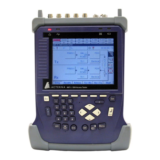
Summary of Contents for Acterna ANT-5
- Page 1 Acterna SDH Access Tester ANT-5, 08.00... User Manual...
- Page 3 Site, www.acterna.com, or contact the nearest Regional Sales Office as listed on the back of the manual. © Copyright 2003 Acterna, LLC. All rights reserved. Acterna, The Keepers of Communications, and its logo are trademarks of Acterna, LLC. All other trademarks and registered trademarks are the property of their respective owners.
- Page 4 This product incorporates VxWorks™ software developed by Wind River Systems Inc., by whom it is copyrighted. ‘MS-DOS’, ‘Windows’ and ‘HyperTerminal’ are registered trademarks of Microsoft Corporation. Page 4 Acterna ANT-5...
-
Page 5: Table Of Contents
1.1 Intended use ........................13 1.2 Features of the SDH Access Tester application software ..........14 1.3 Acterna ANT-5 Software version summary..............14 1.4 Acterna ANT-5 Hardware version summary ..............15 1.5 Physical layout and connectors – BN4565/01..............15 1.6 Physical layout and connectors – BN 4565/02...............17 1.7 Physical layout and connectors –... - Page 6 3.2.8 CompactFlash Cards ..................... 40 3.3 Transferring files to a PC environment ................40 3.3.1 Transferring files from the ANT-5 to a PC using the serial port ......40 3.3.2 File Transfer ......................41 3.4 Available online help ..................... 42 4.
- Page 7 4.10 Results Summary ......................63 4.10.1 Clock Offset results ....................63 4.11 Injection ........................64 4.11.1 Injection of Anomalies...................65 4.11.2 Injection of Bursts errors..................65 4.11.3 Injection of Code errors ..................66 4.11.4 Injection of Defects ....................66 4.12 Performance Analysis Results ..................67 Acterna ANT-5 Page 7...
- Page 8 4.23.1 Exporting data to a spreadsheet using a storage card ......... 84 4.24 On-Screen LED Indicators................... 84 4.25 User Preferences ......................85 4.26 Installed options ......................86 5. Optional software for the ANT-5..................87 5.1 Installing options......................87 5.2 PDH Mux/DeMux......................88 5.2.1 PDH Mux Tx......................88 5.2.2 Sa Bit generation Tx....................
- Page 9 6.4.3 ATM Service Contract Attributes Tx ..............103 6.5 Configuring the Adaptation Layer ................103 6.5.1 ATM SDU Setup Tx ....................103 6.6 Configuring Channel Explorer..................104 6.6.1 Enabling the Channel Explorer ................104 6.6.2 Configuring Explorer Channels................104 6.7 ATM Setup Summary ....................105 6.8 ATM Results ........................105 Acterna ANT-5 Page 9...
- Page 10 7.5 Errors caused by poor optical connections..............112 7.6 Battery performance and conditioning................. 112 7.6.1 Battery conditioning....................113 7.6.2 Replacing the ANT-5 battery pack ............... 113 7.7 Accessing test results if the unit has been powered down.......... 114 8. Customer support ......................115 8.1 Questions about Acterna products ................
- Page 11 9.6.4 CompactFlash Cards – BN 4565/02 onwards............122 9.6.5 T1 testing......................122 9.7 Ordering information ....................122 10. Appendix B – Standards Compliance ................125 10.1 Electromagnetic Compatibility..................125 10.2 Safety.........................125 10.3 R&TTE Directive ......................125 10.4 EC Declaration of Conformity ..................126 Acterna ANT-5 Page 11...
- Page 12 11.3 Serial-to-parallel adapter cable.................. 128 11.4 RJ48 Connector ......................129 12. Appendix D – SDH and PDH information..............131 12.1 SDH structure for ANT-5 ................... 131 12.2 SDH defect hierarchy ....................132 12.3 SDH Tributary Numbering ..................133 12.4 SDH Anomalies and Defects ..................133 12.5 PDH Anomalies and Defects ..................
-
Page 13: Introduction
1. Introduction 1.1 Intended use The Acterna ANT-5 SDH Access Tester is designed to provide all the test functions required by engineers installing and maintaining SDH systems in the Access Network. It can be fitted with the optical and electrical interfaces listed below. -
Page 14: Features Of The Sdh Access Tester Application Software
• Overhead testing including path tracing and injection • Results printing and export (to PC) Optional software for the ANT-5 is discussed in section 5. For more information on purchasing any of these specific features please contact the nearest Regional Sales Office as listed on the back of the manual. -
Page 15: Acterna Ant-5 Hardware Version Summary
A PC Card slot situated on the left of the unit. See section 1.5 for further details. 1.5 Physical layout and connectors – BN4565/01 The ANT-5 has the following external connectors at the rear and side: STM-n FC/PC 1310nm Optical Tx and Rx connectors for STM-1 or... - Page 16 12V DC power 2.5mm 12V Power supply input. For use with type PPS-1 only ANT-5 Serial port 12V DC Attachment Rear view connector Ext power point connector Optical Ext. clock connectors connectors connector ANT-5 Side view RJ48 connector Page 16 Acterna ANT-5...
-
Page 17: Physical Layout And Connectors - Bn 4565/02
If an Rx interface has been selected, but has no signal detected by the application, its LED will flash. 1.6 Physical layout and connectors – BN 4565/02 The ANT-5 has the following external connectors at the rear and side: STM-n FC/PC 1310nm... - Page 18 Introduction Page 18 Acterna ANT-5...
-
Page 19: Physical Layout And Connectors - Bn 4565/03
Introduction 1.7 Physical layout and connectors – BN 4565/03 The ANT-5 has the following external connectors at the rear and side: STM-n FC/PC 1310nm Tx and Rx connectors for STM-1, STM-4 or Optical Tx, Rx and/or 1550nm STM-16. Note: The optical interfaces are optional. -
Page 20: Safety Instructions
1.8.1 Correct usage The ANT-5 should only be used for the purpose and under the conditions for which it is intended. Operation outside these conditions may be dangerous or may damage the instrument. -
Page 21: Laser Safety
WARNING: Invisible laser radiation. Laser light can cause irreparable damage to the eyes, particularly to the retina. • To deactivate the ANT-5 laser source (Tx), clear the Laser On checkbox in the Interface Setup Tx panel. See Section 4.4.2 for further details. -
Page 22: Faults And Damage
With the exception of the battery pack, there are no user serviceable parts in the ANT-5 or its accessories. Do not attempt to open the case of the instrument – any attempt to do so will invalidate the warranty. -
Page 23: Battery Charging
WARNING: The ANT-5 must only be operated from its internal battery or from the included PPS power supply. Ensure that the correct power supply is connected to the appropriate ANT-5. Refer to section 1.5, 1.6 and 1.7 for further details. - Page 24 Introduction Page 24 Acterna ANT-5...
-
Page 25: Getting Started
2. Getting started 2.1 Switching on and off The ANT-5 can be switched on in two ways – either manually, by pressing the On key, or remotely by using a modem or computer to apply a Ring Indicator (RI) signal to the serial port. -
Page 26: Menus
Getting started 2.3 Menus The operating characteristics of the ANT-5 are controlled by sets of hierarchical menus which can be displayed or hidden by pressing Alt+Menu (press Menu whist holding down the Alt key). The highest level of the menu structure is represented by a bar at the top of the screen with one choice highlighted. -
Page 27: Using The Keyboard
Press any key to restore the screen. See Section 2.13, Power saving features. Battery LED Green indicates that the ANT-5 is connected to an external power supply. Flashing green indicates fast charge; steady green indicates trickle charge. - Page 28 Use Alt+Hash to save the current screen in a file or send it to a printer on the serial port, depending on the Screen Dump setting in the Printer section of the System menu. Backlight key Toggle the backlight between high and low level. Page 28 Acterna ANT-5...
-
Page 29: Adjusting The Screen Contrast
To remove the scale from the screen, press the Enter key to accept the new setting or the Esc key to cancel it. The ANT-5 will continue to operate during contrast adjustment but will not receive any keypad input until the adjustment is completed. -
Page 30: Changing The Keypad Settings
Printer section of the System menu. The ANT-5 will sound a series of beeps when the screen has been saved or printed. If the screen is being saved in a file, it is particularly important not to remove the card before these beeps have indicated the end of the process. -
Page 31: Serial Port
See Appendix C – Serial port and adapter cables for a diagram of the serial port. 2.8.1 Comms menu A remote operation option is available for ANT-5, (See Section 5.4), enabling the unit to be operated remotely from a Windows PC. This can be via the telephone network using modems to the V.24 port or over Ethernet. - Page 32 Ethernet port is shown in this graphic. Your IT department will need to know this when assigning the IP address. For PPP operation the ANT-5 acts as the server and is responsible for assigning IP addresses, conversely the PC acts as the slave.
-
Page 33: Card Slot
Cards can be formatted in the ANT-5. See Section 3.2.6 for further details. The cards should be inserted with the label side uppermost. Press into the slot until firmly located. The ANT-5 will beep to indicate it has recognised the card. If no beep is heard refer to section 7.3. -
Page 34: Setting The Time Zone
After making a setting for daylight savings, power off and on the instrument. Verify that the time has changed. Note: The instrument does not automatically adjust the time for daylight savings. You must set or clear this checkbox manually. Page 34 Acterna ANT-5... -
Page 35: Power Saving Features
Power Saving section of the Preferences menu. The ANT-5 will not switch itself off if a test is running. However, if the unit is accidentally switched off, or there is no power left in the battery, results will be saved in the internal: device of the File Manager. -
Page 36: International Features
Select the appropriate language from those listed in the Language section and press the Enter key. Note: The ANT-5 operating system will need to be re-started before this change can take effect. This requires turning the instrument off and then turning it on again. -
Page 37: The Acterna Ant-5 Operating System
3. The Acterna ANT-5 operating system 3.1 Application launcher The ANT-5 can have one or more software applications loaded, each of which will have independent control over the configuration of the measurement hardware and its own results collection, storage and presentation. The available applications are shown as icons on the application launcher screen with the name of each application shown below the icons. -
Page 38: Navigating The File System
Data may be lost from this device in exceptional circumstances when the power-down is not controlled by the operating system, for example if the ANT-5 is switched off by holding the Off key down for more than 6 seconds. -
Page 39: Specifying A Filename
ABC123 RESULTS1 TEST1.DAT Note: The ANT-5 does not support long filenames. If a card containing files with long filenames is inserted into the ANT-5, the long filenames may be lost. 3.2.5 Saving results A FIFO (First-In, First-Out) buffer is used to manage automatically saved files. Results from the last run test are saved as AUTO1.A5R in the internal: device of the file... -
Page 40: Formatting A Card
3.3.1 Transferring files from the ANT-5 to a PC using the serial port (See also 4.23.1, Exporting data to a spreadsheet). The File Manager can be used to transfer data files from the ANT-5 to a PC using the serial port. The following example assumes that Windows HyperTerminal and the... -
Page 41: File Transfer
1. Connect an appropriate serial cable, such as K1524 or K1619, from the ANT-5 to the COM1 port on the PC/Laptop 2. Switch on the ANT-5 and make a note of the Serial Port settings from the System menu. 3. Run Windows HyperTerminal on the PC and choose a name for the connection. -
Page 42: Available Online Help
The Acterna ANT-5 operating system 3.4 Available online help The ANT-5 includes electronic documentation to facilitate testing and interpreting test results. All documentation is available from the Help menu. To access the Help menu, press Menu on the keypad. Help > About Select this option to view version information. -
Page 43: The Sdh Access Tester Application
Results view allows the user to view the test results as a test is running or after it has been stopped. Results view also provides facilities for injecting anomalies and defects and selecting different displays of test results. Acterna ANT-5 Page 43... -
Page 44: General Screen Layout
• The six unmarked keys at the top of the keyboard, , are function keys to control certain features of the ANT-5. The function of each active key is identified by an animated button on the screen just above the actual key. -
Page 45: Status Bar
For example BIT will be shown if G.821 is selected. Assuming the ATM option has been purchased and enabled (see Section 6) this icon (position d) becomes animated when load ATM traffic is monitored at the receiver (Rx). Acterna ANT-5 Page 45... -
Page 46: Function Keys
The six unmarked keys at the top of the keyboard, , are function keys to control certain features of the ANT-5. The function of each active key is identified by an animated button on the screen just above the actual key. The state of each button icon, whether it is shown pushed in or not, is also used to indicate current functional states such as Setup view or Results view. -
Page 47: Setup
The SDH Access Tester application uses a range of tabbed setup pages to set the interface and test parameters before running a test. The settings can be easily changed by moving around the screen with the directional keys and selecting items Acterna ANT-5 Page 47... -
Page 48: Measurement Selection
4.20 VC12 Tributary Scanning Setup VC12 Tributary Scanning Results 4.16 Note: To select Tributary Scan ensure VC12 is selected as the Virtual Container for the Transmitter (Tx) and the Receiver (Rx). (See Section 4.4.3 and 4.4.9). Page 48 Acterna ANT-5... -
Page 49: Signal Structure Setup Page
LSS defects. When setting up the various parts of the signal structure for the ANT-5, it is advisable to make changes to each element of the structure in the order that they are referred to in this chapter. -
Page 50: Hierarchy Setup Tx
However, if the limits are exceeded a NE will fail to synchronise to the received signal which will result in network errors. Skewing the frequency is a standard test during installation to ensure that an installed unit can tolerate the frequency offsets occurring within the network. Page 50 Acterna ANT-5... - Page 51 Output The output interface can be set to either Optical or Electrical. If the ANT-5 is equipped with an optical interface, both electrical and optical options will be available. If a PDH structure has been selected in the Hierarchy setup, the optical options will be disabled.
-
Page 52: Virtual Container Setup Tx
As an alternative to selecting the discrete TUG and TU numbers, the corresponding number of the Virtual Container can be selected. This is of benefit when setting up VC-12s or other complicated mappings. On entering a VC number, the TUG and TU Page 52 Acterna ANT-5... -
Page 53: Pdh Setup Tx
‘I’ at the beginning of the pattern name, for example IPRBS23 is the inverted form of the 2 -1 pattern, PRBS23. Note: The pattern element will be greyed out if the round trip delay measurement has been activated. See 4.20 for further information. Acterna ANT-5 Page 53... -
Page 54: Hierarchy Setup Rx
PDH structure has been selected in the Hierarchy setup, the optical options will be disabled. If an SDH structure has been selected and the ANT-5 is equipped with an optical interface, both electrical and optical options will be available. If the Optical interface is selected, the receiver interface will... -
Page 55: Virtual Container Setup Rx
If testing within a PDH hierarchy is required, the PDH tributary should be selected. The test pattern will then be injected into the selected SDH virtual container with the selected PDH parameters. Note: VC11/TU11 and VC11/TU12 will also become selectable if the option has been purchased and enabled. Acterna ANT-5 Page 55... -
Page 56: Channel Setup Rx
Pattern Type selector. Inverted patterns are also available and are indicated by an ‘I’ at the beginning of the pattern name, for example IPRBS23 is the inverted form of the 2 -1 pattern, PRBS23. Page 56 Acterna ANT-5... -
Page 57: Symmetrical Tx And Rx Settings
Note: Previous mixed mode configurations saved prior to software version 08.00 will no longer be valid. 4.5 Overhead Setup The Overhead Setup page has five separate sub-pages which can be viewed by selecting the appropriate entry in the View menu at the top of each page. Acterna ANT-5 Page 57... -
Page 58: Transmitted Trace Identifiers
‘A’ to ‘F’. The two hexadecimal digits can be entered by using the keyboard for the decimal numbers and the function keys for the alpha characters. Page 58 Acterna ANT-5... -
Page 59: Path Labels
HP and LP check boxes as required. The appropriate paths will then activated on the TCM results page. If neither box is selected, the TCM results page will not be available. See Section 4.15, TCM results summary. Acterna ANT-5 Page 59... -
Page 60: Au Pointer Value
Duration The test can be set to run for a specified Duration from 1 second up to 99 days. The time selected will be shown on the status bar. Page 60 Acterna ANT-5... -
Page 61: Performance Analysis Setup
30% of the number of blocks in one second. UAS Limit allows setting of the threshold for Unavailable Seconds, in G.826 said to be 10 consecutive seconds of SES. This can be disabled by clearing the adjacent checkbox. Acterna ANT-5 Page 61... -
Page 62: Vc12 Tributary Scanning Setup
This can involve testing each VC12 tributary in an STM-4 – possibly 252 tributaries. The Acterna ANT-5 is able to automatically scan individual or multiple tributaries to verify the routing and error free operation. A pass/fail indication is given for each VC12 tested. -
Page 63: Results
4.10.1 Clock Offset results Once the test has started the ANT-5 samples the received signal from the network element then calculates and displays the result of the frequency offset. The ANT-5 displays the Rx offset to check a network element is transmitting correctly. -
Page 64: Injection
PDH anomalies can be injected. In addition to injecting into either the SDH or PDH structures, injection of TSEs (bit errors) into the relevant payload is also available using the Transmit Pattern. Page 64 Acterna ANT-5... -
Page 65: Injection Of Anomalies
Errors are injected into consecutive SDH frames. This process is then repeated, the Repetition Period is defined in frames or seconds which gives a convenient method of testing frame synchronization. Acterna ANT-5 Page 65... -
Page 66: Injection Of Code Errors
Repetition period = 5 frames Note: The value for the Repetition Period is always greater than the value of the Frames. The ANT-5 will automatically adjust the values if necessary. 4.11.3 Injection of Code errors To allow for in-service performance analysis, E1 (2M) code errors can be injected into the PDH structure. -
Page 67: Performance Analysis Results
This screen displays the Analysis standard and selected Hierarchy, and will list all relevant results parameters, in both absolute number of seconds and also as a percentage of the total test duration. Acterna ANT-5 Page 67... -
Page 68: Anomalies And Defects Results
Note: Defect panel LED’s turn yellow during a test to show historic alarms, that is, defects that have been raised during a test but are not currently active. To reset the LEDS press Alt and Menu and select System >LEDs >Reset LEDs. Page 68 Acterna ANT-5... -
Page 69: Event Log
The time scale is shown under the chart, and can be set to a resolution of 60 days, hours, minutes or seconds by pressing the keys. Vertical columns show sub-divisions of 10 Acterna ANT-5 Page 69... - Page 70 5. Use the left/right directional keys to scroll the graph horizontally in steps of 10 time units. For faster scrolling hold the Alt key down to increase the step size to 60 time units. Page 70 Acterna ANT-5...
-
Page 71: Overhead Analysis And Injection
Use the directional keys to move to another part of the screen. 4.14 Overhead Analysis and Injection The SDH overhead byte structure can be displayed for either transmit or receive paths by selecting the tab for Overhead Analysis/Injection. Acterna ANT-5 Page 71... -
Page 72: Summary View
In Analysis mode, the received section and path overhead bytes (SOH & POH) are displayed, and are continually updated every second. In Injection mode, the transmitted SOH & POH bytes are displayed. Page 72 Acterna ANT-5... - Page 73 To conclude the examination or editing of individual bytes, press the Esc key to deselect the table and return to the page tabs. Acterna ANT-5 Page 73...
-
Page 74: Tcm Results Summary
Section 4.10. More detailed results can be found in the Event Log, as described in Section 4.13.2. For an application note on this topic, visit our Web Site, www.acterna.com, or contact the nearest Regional Sales Office as listed on the back of the manual. -
Page 75: Vc12 Tributary Scanning Results
(Multiple failures are indicated below the list). In this example MS-REI and HP-REI failures are present in the 1,1:5:1 tributary. A verdict of the overall result will be displayed on completion of the test. Acterna ANT-5 Page 75... -
Page 76: Repetitive Bert
Detection achieved monitoring the reduction in Quality of Service (QoS) or monitoring the resultant alarms. Depending on the signalling structure the following sensors can be selected, TSE, MS-AIS, AU-AIS and TU-AIS. Page 76 Acterna ANT-5... -
Page 77: Pointer Analysis
Rx. The TU column will only be visible if there is a tributary path set within the signal structure. It is advisable that From Rx is set as the Clock Source in the Interface Setup Tx panel. Acterna ANT-5 Page 77... -
Page 78: Delay
Delay on the signal structure page which will be greyed out. 4.21 Nx64 The ANT-5 can perform BER testing on a single user selectable 64k timeslot; where each timeslot has traditionally been used to carry a voice channel; alternatively multiple timeslots can be tested, supporting data pipe services which can consist of any permutation of timeslots. -
Page 79: Functionality
OK or to move to another part of the screen. Note: The ANT-5 will only be able to transmit and receive nx64 when E1 framing is part of the hierarchy. Channel 0 is used for FAS/NFAS and will always be greyed out;... -
Page 80: Optical Power Measurement
+/- 3dB. In this example, an Optical Level of –14dBm has been received. 4.22.3 PECL NRZ STM monitor port With the Rate set to STM-16 NRZ signals can be monitored at the electrical monitor point without the need for optical spitters. Page 80 Acterna ANT-5... -
Page 81: E1 Hi-Z Input
ANT-5, which has previously been saved either to a card or to the ANT-5 RAM. The file window will list all valid configuration files on either the card if it is inserted, or in the ANT-5 RAM, along with their date and time of creation and a brief description. - Page 82 ANT-5 RAM. The file window will list all valid results files on either the card if it is inserted, or in the ANT-5 RAM, along with their date and time of creation and a brief description. The results...
- Page 83 The SDH Access Tester application Note2: Previous mixed mode configurations saved prior to software version 08.00 will no longer be valid. Acterna ANT-5 Page 83...
-
Page 84: Exporting Data To A Spreadsheet Using A Storage Card
Alt + Menu key at any time. If the Latching box is checked, you can reset all latched LED’s by selecting Reset LEDs from the System menu or alternatively LEDs can be reset from within the ANT-5 application by pressing Menu, and selecting Tools > Reset LEDs. -
Page 85: User Preferences
Note: Another icon will be present only when the GUI is used with the Remote Operation option. Select the cable icon to change the IP Address of the ANT-5. If the IP address is edited whilst running the application, close and restart to enable the change. -
Page 86: Installed Options
4.26 Installed options Options currently installed can be displayed by pressing the Menu key from within the ANT-5 application, and selecting Options from the Tools menu. This screen is also used to install and uninstall options, See Section 5.1 Installing options for further details. -
Page 87: Optional Software For The Ant-5
Note: Options purchased with a factory built ANT-5 will already be installed. 5.1 Installing options New options purchased for the ANT-5 will be supplied with an access code. Options are enabled as follows: - From within the application an access Key... -
Page 88: Pdh Mux/Demux
Complex, interlocking signal paths can result, particularly within modern SDH cross-connects. Here, the ANT-5 can be used to test complex switching functions. The PDH Mux feature allows the generation of ITU-T Mux chains from E1 to E4, starting and finishing at any intermediate rate with the exception of E2 (i.e. -
Page 89: Sa-Bit Monitoring
Optional software for the ANT-5 5.2.3 Sa-bit monitoring Assuming the Rx signal structure is configured to receive framed E1 signals, then Sa bits can also be monitored by pressing the Results firmkey and selecting the SA tab. 5.2.4 PDH DeMux Rx... -
Page 90: Remote Operation
Optional software for the ANT-5 Container Setup panel to VC4-4c. 5.4 Remote Operation Before starting it is advisable to note the communication settings of the ANT-5. Press Alt+Menu and select Comms… from the System menu, then select PPP and/or Ethernet as required. - Page 91 OK to proceed. If required, the IP address can be edited. Note 2: When typing in the ANT-5 IP address into a PC environment care should be taken to avoid any leading zeros. For example 141.169.126.076 would be replaced with 141.169.126.76.
-
Page 92: Exporting
Optional software for the ANT-5 After a short while the ANT-5 graphical user interface will load on the PC, green LEDs will flash in the Tx and Rx boxes of the ANT-5 indicating that the link has been established. The PC’s mouse and keyboard are used to operate the remote ANT-5 just as if you were sitting in front of it. -
Page 93: Remote Control
Optional software for the ANT-5 5.5 Remote Control Refer to Acterna’s ANT-5 Remote Control User Manual for more information. 5.6 SONET 5.6.1 Introduction Synchronous optical network, known as SONET, is the standard for synchronous operation used primarily in North America and is defined by ANSI T1. (American National Standards Institute –... -
Page 94: Synchronous Payload Envelope Setup
Optional software for the ANT-5 5.6.3 Synchronous Payload Envelope Setup SPE Mappings can be selected from the Synchronous Payload Envelope Setup element. This element will not be available if a PDH interface has been selected. Bulk should be selected as the Tributary if bulk testing of the virtual container is required. -
Page 95: Sonet Information
Mapping Concatenated option only VT mapping option only SONET Anomalies and Defects The following table lists the SONET Anomalies and Defects pertinent to ANT-5, their meanings and detection criteria. Anomalies Detection Criteria Loss of signal All-zero pattern for ≤ T ≤ 100 µ... - Page 96 Optional software for the ANT-5 Anomalies Detection Criteria RDI-L Remote Defect Indication – Line K2 (bits 6,7,8) = 110 for ≥ z frames (z = 5 to 10) LOP-P Loss of Pointer – STS Path 8 to 10 NDF enable...
-
Page 97: Sdh Au-3/Sonet Vt Mapping
Optional software for the ANT-5 5.7 SDH AU-3/SONET VT Mapping AU-3 Mapping enables the testing of DS-1, E1, E3 and DS3 tributaries mapped into STM-1 via VC-3/ AU-3, as shown in the following diagram. 2396160 kbit/s STM-16 AUG16 AU-4-16c VC-4-16c... - Page 98 Optional software for the ANT-5 The VT mapping function enables the testing of DS-1 and E1 tributaries mapped into an STS-1 SPE via VT1.5 and VT2 SPE’s as shown in the following diagram. However, this option also requires the SONET option BN 4565/00.62.
-
Page 99: Asynchronous Transfer Mode - Atm
Transmission medium 6.2 Introduction The ATM option expands the applications of the ANT-5 to cover use in ATM networks. The measurement methods and user interface have been designed for applications involving user-network interfaces (UNI) and network-network interfaces (NNI). -
Page 100: Atm Setup And Result Tabs
Tx or the Rx structure, and then pressing either the keys as appropriate. The structure will be copied from Tx to Rx, or vice versa, as selected. Page 100 Acterna ANT-5... -
Page 101: Virtual Container Setup Tx
Channel B is used to carry a fixed payload type on the background channel. Click on OK when you have set the parameters. From the signal structure page move the directional keys over Traffic Off panel. The Enter key can be used to switch Traffic On or Traffic Off as required. Acterna ANT-5 Page 101... -
Page 102: The Atm Structure
Four bits are used for Generic Flow Control GFC. These bits control the flow of data between the user and the network. GFC can only be set if UNI is selected as the Interface. See section 6.4, Configuring the ATM Layer for further details. Page 102 Acterna ANT-5... -
Page 103: Atm Service Contract Attributes Tx
The O.191 measurement tests performance on a cell-by-cell basis in the ATM layer. The function and performance of other payload types must be considered separately. For example, the payload type for Channel B will be fixed. Acterna ANT-5 Page 103... -
Page 104: Configuring Channel Explorer
Asynchronous Transfer Mode – ATM The Test Cell Format standard is ’97 Format. For example, this format is backwardly compatible with Acterna ANT-20 Broadband Analyzer/ Generator module. The ’95 Format is backwardly compatible with equipment that uses legacy applications. 6.6 Configuring Channel Explorer 6.6.1 Enabling the Channel Explorer... -
Page 105: Atm Setup Summary
If any defects or anomalies occur during a test, the large OK is replaced by a list of continually updated defects and anomalies that have been detected by the instrument during the test. Acterna ANT-5 Page 105... -
Page 106: Injection Of Atm Anomalies And Defects
• Load is the number or percentage of cells that contains user information, including OAM cells • Idle/Unassigned is the number or percentage of cells received • CLP =1 Count of cells where CLP=1. If congestion causes a problem, the network will discard these cells first Page 106 Acterna ANT-5... -
Page 107: Atm Quality Of Service
QoS to ITU-T O.191. Cells exceeding the specified maximum delay are assumed to be of significantly reduced value to the application. Acterna ANT-5 Page 107... -
Page 108: Viewing Results From The Channel Explorer
Asynchronous Transfer Mode – ATM 6.8.5 Viewing Results from the Channel Explorer The Channel Explorer lists results for channels on which the ANT-5 conducts tests. You can scroll down the entire list of channels, or type channel numbers in the VPI and VCI text boxes. -
Page 109: Event Log
The list of anomalies or defects is shown on the left of the chart and can also be scrolled vertically if required. Refer to section 4.13.4, Graphs for an example on how to use the detailed zoom feature. The benefit of the Acterna ANT-5 Page 109... -
Page 110: Atm Led Indicators
Test Sequence Err. (Bit Err.) Loss of Sequence Sync. 6.11 Further reading A useful resource is Acterna’s ATM Pocket Guide. (Literature order number: TP/EN/PG04/0400/AE Repl. 1020.) This guide introduces the basics of ATM and gives some details on various measurement methods. -
Page 111: Troubleshooting
Acterna Sales Office or Technical Assistance Centre. Note: When the battery charge is very low, it may be possible for the ANT-5 to switch on but fail to complete its self-test procedure before automatically switching off due to the low battery. -
Page 112: Screen Dump Fails
If the failure continues please refer to Section 8, Customer support, and contact the nearest Acterna Sales Office or Technical Assistance Centre. If it is necessary to send the ANT-5 for repair, the storage card should be included if possible. -
Page 113: Battery Conditioning
1. Switch off the ANT-5 and disconnect all connections and the external mains power supply. 2. Invert the ANT-5 so that the underside is uppermost and the front bumper is closest to you. Take care to protect the screen and keyboard if the ANT-5 is placed on a hard surface. Acterna ANT-5... -
Page 114: Accessing Test Results If The Unit Has Been Powered Down
7.7 Accessing test results if the unit has been powered down. The ANT-5 will not switch itself off if a test is running. However, if the unit is accidentally switched off, or there is no power left in the battery, results will be saved in the internal: device of the File Manager. -
Page 115: Customer Support
8.1 Questions about Acterna products Any questions regarding the installation, operation, maintenance or repair of any product in the Acterna product range should be addressed to the nearest Acterna Sales Office or Technical Assistance Centre. For locality information visit our web site, www.acterna.com, or contact the nearest Regional Sales Office as listed on the back... -
Page 116: Software Loading
Software applications can be deleted by highlighting the appropriate icon in the application launcher screen and pressing Alt+Del (press Del whilst holding the Alt key down). Next time the ANT-5 is switched on it will run a purging routine to reclaim the memory which has been made available. -
Page 117: Appendix A - Specifications And Ordering Information
Weight ..................approx. 2.2 kg (4.85 lb) 9.2 External Power Supply BN4565/01 series Type ........................PPS-1 Input .................100-240V, 0.7A, 50/60Hz, AC Output ......................12V, 2.5A, DC BN 4565/02 onwards Type ........................PPS-2 Input .................100-240V, 1.6A, 47/63Hz, AC Output ......................19V, 3A, DC Acterna ANT-5 Page 117... -
Page 118: Environment
RJ48 (2048 kbit/s balanced) ....120Ω Bit rate ............2048, 34368, 44736, 139264, 155520 kbit/s Jitter performance .........To ITU-T G.823 G.824 for DS3, G.825 for SDH Line code ................... CMI, B3ZS, HDB3 Isolation, BNC and RJ48.........for connection to SELV circuits only Page 118 Acterna ANT-5... -
Page 119: Protected Monitor Point
Bit errors may be encountered when √f and jitter are both at their maximum permitted values. In addition the following precautions should be taken: The ANT-5 should be allowed to stabilise to an ambient temperature for a period of 5 minutes before any measurements are taken. -
Page 120: Ecl Nrz Monitor Specifications
Measurement results and instrument configuration can be stored in non-volatile memory or on the storage card. The amount of storage depends on the size of card used. Results can also be sent to a printer or exported to a PC. Page 120 Acterna ANT-5... -
Page 121: Test Patterns
SONET........................ANSI 9.6 Optional Accessories The range of optional accessories available for the ANT-5 includes a shoulder bag, neck strap and hard carrying cases. Please contact the nearest Acterna Sales Office or Technical Assistance Centre for the latest information. For locality information visit our web site, www.acterna.com, or contact the nearest Regional Sales Office as... -
Page 122: Hardware Options And Order Numbers
Bit rates using the T1 input impedance of 100Ω can be tested using the E1 BNC Tx and Rx interfaces on the ANT-5. An optional balum and cables can be purchased from Acterna, (BN4565/00.78). Contact the nearest Acterna Sales Office or Technical Assistance Centre for further details. - Page 123 Appendix A – Specifications and ordering information Note: When purchasing further items to expand existing hardware and software, some identification details may be required. Refer to Section 8.4, Version information and serial numbers, for further information. Acterna ANT-5 Page 123...
- Page 124 Appendix A – Specifications and ordering information Page 124 Acterna ANT-5...
-
Page 125: Appendix B - Standards Compliance
The following only applies if optical interfaces are fitted: WARNING: Class 1 Laser Product. 10.3 R&TTE Directive Hereby Acterna declares that this SDH Tester is in compliance with the essential requirements and other relevant provisions of Directive 1999/5/EC. Acterna ANT-5... -
Page 126: Ec Declaration Of Conformity
Appendix B – Standards Compliance 10.4 EC Declaration of Conformity Page 126 Acterna ANT-5... -
Page 127: Appendix C - Serial Port And Adapter Cables
Appendix C – Serial port and adapter cables 11. Appendix C – Serial port and adapter cables 11.1 Serial port The ANT-5 serial port is 9-way, male, D-type connector which is wired as a DTE. Serial port connections (DTE) DTR (+5V) SGND 11.2 Serial adapter cables... -
Page 128: Serial-To-Parallel Adapter Cable
A serial-to-parallel printer cable, K1589, is available to convert the serial output from the ANT-5 for use with parallel printers. It comes with a 9-way to 25-way adapter. It is advisable to connect the printer cable to the ANT-5 before switching the unit on. -
Page 129: Rj48 Connector
Appendix C – Serial port and adapter cables 11.4 RJ48 Connector RJ48 Connector Not used Not used XT=Tip, XR=Ring and XG=Ground Acterna ANT-5 Page 129... - Page 130 Appendix C – Serial port and adapter cables Page 130 Acterna ANT-5...
-
Page 131: Appendix D - Sdh And Pdh Information
Appendix D – SDH and PDH information 12. Appendix D – SDH and PDH information 12.1 SDH structure for ANT-5 2396160 kbit/s STM-16 AUG16 AU-4-16c VC-4-16c C-4-16c 599040 kbit/s* STM-4 AUG4 AU-4-4c VC-4-4c C-4-4c 139264 kbit/s STM-1 AUG1 AU-4 VC-4... -
Page 132: Sdh Defect Hierarchy
Higher Order Lower Order Section Section Path Path LOS/LOF RS-TIM BIP Error MS-AIS MS-BIP Error MS-REI MS-RDI AU-AIS AU-LOP HP-UNEQ HP-TIM HP-BIP Error HP-REI HP-RDI TU-AIS TU-LOP HP-PLM LP-UNEQ LP-TIM LP-BIP Error LP-REI LP-RDI LP-PLM Detection Generation Page 132 Acterna ANT-5... -
Page 133: Sdh Tributary Numbering
Loss of signal Test sequence error (bit error) Loss of Sequence Synchronisation Alarm indication signal Regenerator Section Out of frame A1, A2 Loss of frame A1, A2 Regenerator section error monitoring RS-TIM RS trace identifier mismatch Acterna ANT-5 Page 133... - Page 134 LO path remote defect indication LP-REI LO path remote error indication LP-RFI LO path remote failure indication LP-TIM LO path trace identifier mismatch LP-PLM LO path payload label mismatch BIP-2 LO path error monitoring (VC-11/VC-12) LO path error monitoring (VC-3) Page 134 Acterna ANT-5...
-
Page 135: Pdh Anomalies And Defects
DS3 Defect Description Loss of Signal Loss of Frame Out of Frame Alarm Indication Signal (1010 payload) IDLE DS3 Idle (1100 payload) YELLOW Yellow alarm (Far End Alarm) Loss of Sequence Synchronisation Acterna ANT-5 Page 135... - Page 136 Alarm Indication Signal Remote Defect Indication Loss of Sequence Synchronisation E3 Anomaly Description Frame Alignment Signal Test Sequence Error E1 Defect Description Loss of Signal Loss of Frame Alarm Indication Signal Remote Defect Indication Loss of Sequence Synchronisation Page 136 Acterna ANT-5...
-
Page 137: Comparison Of Sdh/Sonet Anomalies And Defects
ADMINISTRATIVE UNIT (AU) STS – PATH (SP) AU-LOP Loss of AU Pointer LOP-P SP Loss of Pointer AU-NDF New Data Flag AU Pointer NDF-P SP New Data Flag AU-AIS AU-AIS AIS-P SP AIS AU-PJE AU Pointer Justification Acterna ANT-5 Page 137... - Page 138 LO Path Remote Failure LP-RFI VP Remote Failure Indicator Indicator PDI-V VP Payload Defect Indicator LP-TIM TIM-V VP Trace Identifier Mismatch LO Path Trace Identifier Mismatch LP-PLM PLM-V VP Payload Label Mismatch LO Path Payload Label Mismatch Page 138 Acterna ANT-5...
-
Page 139: Appendix E - Performance Analysis Options
Appendix E – Performance Analysis Options 13. Appendix E – Performance Analysis Options For an application note on this topic, visit our Web Site, www.acterna.com, or contact the nearest Regional Sales Office as listed on the back of the manual. -
Page 140: Recommendation G.826
The recommended measurement time for G.821 and G.826 is 30 days. 13.2.3 Recommendation G.828 Unlike G.826, recommendation G.828 provides a precise block length for each bit rate. For example, the number of blocks monitored per second for bit rates from VC3 upwards remains constant at 8000. Page 140 Acterna ANT-5... -
Page 141: Recommendation G.829
The recommendation defines the block size, number of blocks per SDH frame, number of blocks transmitted per second and the error detection code (EDC) to be used for the various SDH bit rates that your ANT-5 supports. 13.2.5 Recommendation M.2100 Recommendation M.2100 specifically applies to commissioning and maintenance. - Page 142 Appendix E – Performance Analysis Options Page 142 Acterna ANT-5...
-
Page 143: Appendix F - Remote Access
ANT-5. • A PC or device for sending commands down a serial cable. 1. Check the Baud Rate on the ANT-5 is 57600, by pressing Alt + Menu and selecting Comms from the System menu. 2. Connect the modem to the PC/laptop using an appropriate serial cable. -
Page 144: Setting Up A Pc Using Windows 98
Once the modem is successfully configured, remove the serial cable from the PC and connect this to the ANT-5 without disconnecting the power to the modem or switching it off, so ensuring that the modem indicator lights remain on. - Page 145 Connection. Type in a connection name and select the modem to be used and select Next. 2. Type in the phone number of the remote ANT-5, select Next and select Finish in the next frame. 3. From the newly created connection (e.g. ANT-5 Remote Connection) right click and select Properties.
- Page 146 Appendix F - Remote Access 4. From Server Types emulate the following settings:- 5. Click on TCP/IP Settings… and again emulate the following settings:- 6. Click on OK and then OK again to finish. Page 146 Acterna ANT-5...
- Page 147 • Select Start > Run. • In the Run dialog box, type msconfig.exe and click OK. The System Configuration Utility appears. • Click the Autoexec.bat tab. • If there is a statement such as SET TZ=GMT+1 (or similar), delete it. Acterna ANT-5 Page 147...
- Page 148 8. If you are connecting to a BN4565/01, define a TZ environment variable. Do the following: • Select Start > Run. • In the Run dialog box, type msconfig.exe and click OK. The System Configuration Utility appears. • Click the Autoexec.bat tab. Page 148 Acterna ANT-5...
- Page 149 REMOTE application and leave on. 10. From Dial-Up Networking double click on the icon for the ANT-5 remote connection and select Connect. 11. The modem will then dial out to the remotely located ANT-5 modem and establish a connection. Acterna ANT-5...
-
Page 150: Setting Up A Pc Using Windows Nt
• Phone number of the remote ANT-5 (including country/area codes). 1. From Start > Programs >Accessories > Dial-Up Networking click on New. Type in a name for the connection and the phone number of the remote ANT-5. (It is advisable to uncheck Use another port if busy). - Page 151 Appendix F - Remote Access 2. Click on the Server tab, and emulate the following settings. 3. Click on TCP/IP Settings… and again emulate the following settings. Click on OK to proceed. Acterna ANT-5 Page 151...
- Page 152 Appendix F - Remote Access 4. From the Script tab emulate the following settings. 5. Click on the Security tab to emulate the following settings. Page 152 Acterna ANT-5...
- Page 153 8. If you are connecting to a BN4565/01, define a TZ environment variable. Do the following: • Select Start > Settings > Control Panel > System. • Click the Environment tab. • Click New. The New System Variable dialog box appears. • Type TZ in the Variable Name field. Acterna ANT-5 Page 153...
- Page 154 REMOTE application and leave on. 10. Click Dial from the next screen. 11. The modem will then dial out to the remotely located ANT-5 modem and establish a connection. Note: A password is not mandatory since the password facility of Windows Dial-up Networking is not used by ANT-5.
-
Page 155: Setting Up A Pc Using Windows 2000
• Windows networking for TCP/IP. • Dial-up networking. • A correctly installed and configured modem. • Phone number of the remote ANT-5 (including country/area codes). 1. From the Start menu, select Settings > Network and Dial-up Connections > Make New Connection. - Page 156 4. Configure the phone number to dial as shown below, then click Next. (The modem may have to be configured to access an external line via the telephone network). 5. If prompted, decide who is going to use this connection, then click on Next. Page 156 Acterna ANT-5...
- Page 157 Appendix F - Remote Access 6. Name the connection, for example ANT-5 Remote Operation Unit then click Finish. 7. You will now have a new dial-up network connection icon in the dial-up networking window, called ANT-5 Remote Operation Unit. Acterna ANT-5...
- Page 158 Appendix F - Remote Access 8. Right click on the ANT-5 Remote Operation Unit, and select Properties from the menu. The following dialog box appears: 9. Select the Options tab and emulate the following settings. Page 158 Acterna ANT-5...
- Page 159 Ensure that the Internet Protocol (TCP/IP) box is checked. The greyed options (Novell Distributed Print Services and Workstation Manager) below are disabled by Windows 2000. (You may have some components like this, as this is normal. Ensure that all other components are unchecked). Acterna ANT-5 Page 159...
- Page 160 12. Click the Internet Protocol (TCP/IP) component, and then click Properties. The following dialog box appears. 13. Click Advanced…, and from the General Tab, uncheck Use default gateway on remote network and the click OK. 14. Click OK, close the Internet Protocol (TCP/IP) Settings dialog box. Page 160 Acterna ANT-5...
- Page 161 15. If privileges allow select the Sharing tab, and emulate the following settings. Click OK to close the ANT-5 Remote Operation Unit Properties dialog. 16. If you are connecting to a BN4565/02 or BN4565/03, be sure there is no TZ environment variable.
-
Page 162: Remote Operation Via Ethernet (Ieee 802.3)
149. • Click OK, and exit the Control Panel. 18. A connection to an external power supply is advisable. Reboot the ANT-5, launch the REMOTE application and leave on. 19. From Network and Dial-up Connections double click on the icon for the ANT-5 remote connection. -
Page 163: Keyboard Equivalents
Appendix F - Remote Access 2. In the Systems > Comms > Ethernet menu of the ANT-5, edit the IP Address, Subnet Mask and Gateway to those specified by the IT department and the Transceiver to the network connection type. - Page 164 Appendix F - Remote Access Page 164 Acterna ANT-5...
-
Page 165: Appendix G - Glossary & Acronyms
BIP-N Bit Interleaved Parity; N bits BIS[P]O Bringing into service [performance] objectives Signal label (VC-3, 4 POH) Channel Associated Signalling Constant Bit Rate Cross-Connect Multiplexing Cell Delay Variation CDVT Cell Delay Variation Tolerance Cell Error Rate Acterna ANT-5 Page 165... - Page 166 Electrical interface signal, 8448 kbit/s. Also service channel (voice) in multiplex section (MSOH). Electrical interface signal, 34368 kbit/s Electrical interface signal, 139264 kbit/s Errored Block Count Embedded Communication Channel Emitter Coupled Logic Error Detection Code Error-Free Second Page 166 Acterna ANT-5...
- Page 167 Regenerator section trace (RSOH) Path trace (POH in VC-3, VC-4) Path trace (POH in VC-12) K1, K2 APS channels for APS sig. & back-up line switching (MSOH) K3, K4 APS channels for APS sig. & back-up line switching (POH) Acterna ANT-5 Page 167...
- Page 168 Maximum Time Interval Error Network operator byte for TCM in VC-3, VC-4 Network operator byte for TCM in VC-12 New Data Flag Network Element NFAS Not Frame Alignment Signal Network Node Interface Operation, Administration and Management Page 168 Acterna ANT-5...
- Page 169 Remote Defect Indicator, Remote Error Indicator ROSE Remote Operations Service Element RSOH Regenerator Section Overhead Synchronisation status byte (MSOH) Segmentation and Reassembly Synchronous Digital Hierarchy Sustainable Cell Rate Service Data Unit SDH Equipment Clock SEFS Severely Errored Framed Seconds Acterna ANT-5 Page 169...
- Page 170 User Network Interface µs Microseconds POH byte (VC-1, 2) Variable Bit Rate VC, VC-n Virtual Channel, Virtual Container; Level n = 1, 2, 3, 4 VC-n-Xc Concatenated virtual container, level n, X concatenated VCs Virtual Channel Identifier Page 170 Acterna ANT-5...
- Page 171 Appendix G – Glossary Virtual Path Virtual Path Identifier Virtual Tributary WDM, DWDM Wavelength Division Multiplexing, Dense WDM Acterna ANT-5 Page 171...
- Page 172 Appendix G – Glossary Page 172 Acterna ANT-5...
- Page 174 04571-000 São Paulo Germany Communications, and its SP-Brazil Tel: +49 7121 86 2222 Acterna is present in more logo are trademarks of Toll Free: 1 866 ACTERNA Tel: +55 11 5503 3800 Fax:+49 7121 86 1222 than 80 countries. To find Acterna, LLC.
Need help?
Do you have a question about the ANT-5 and is the answer not in the manual?
Questions and answers