Table of Contents
Advertisement
Quick Links
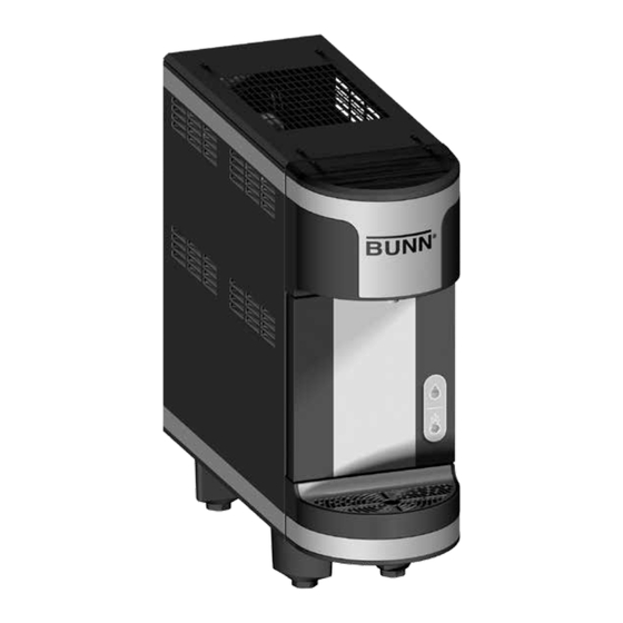
BUNN refresh™
INSTALLATION & OPERATING GUIDE
BUNN-O-MATIC CORPORATION
POST OFFICE BOX 3227
SPRINGFIELD, ILLINOIS 62708-3227
PHONE: (217) 529-6601
FAX: (217) 529-6644
To ensure you have the latest revision of the Operating Manual, or to view the Illustrated Parts
Catalog, Programming Manual, or Service Manual, please visit the Bunn-O-Matic website, at
www.bunn.com. This is absolutely FREE, and the quickest way to obtain the latest catalog and
manual updates. For Technical Service, contact Bunn-O-Matic Corporation at 1-800-286-6070.
52373.0000C
09/16 ©2015 Bunn-O-Matic Corporation
Advertisement
Table of Contents

Summary of Contents for Bunn MCR
- Page 1 To ensure you have the latest revision of the Operating Manual, or to view the Illustrated Parts Catalog, Programming Manual, or Service Manual, please visit the Bunn-O-Matic website, at www.bunn.com. This is absolutely FREE, and the quickest way to obtain the latest catalog and manual updates. For Technical Service, contact Bunn-O-Matic Corporation at 1-800-286-6070.
-
Page 2: Warranty
AS SPECIFIED HEREIN, TO REPAIR, REPLACEMENT OR REFUND. In no event shall BUNN be liable for any other damage or loss, including, but not limited to, lost profits, lost sales, loss of use of equipment, claims of Buyer’s customers, cost of capital, cost of down time, cost of substitute equipment, facilities or services, or any other special, incidental or consequential damages. -
Page 3: Table Of Contents
CONTENTS Warranty ........................2 User Notices ........................3 Initial Set-Up & Electrical Requirements ................ 4 CE Requirements ......................4 Plumbing Requirements ....................5 Plumbing Hookup ......................5 Carbon Dioxide Hookup ....................5 Filling the Water Bath ..................... 6 Purging the Water Lines ....................6 Changing Water Filter Cartridge Warning ............... -
Page 4: Initial Set-Up & Electrical Requirements
INITIAL SET-UP CAUTION: The dispenser is very heavy! Use care when lifting or moving it. Use at least two people to lift or move the dispenser. Place dispenser on a sturdy counter or shelf able to support at least 125 lbs. (57 kg). The dispenser is designed for indoor use only, in ambient temperatures ranging from 50°F to 90°F (10°C to 32°C). -
Page 5: Plumbing Requirements
BUNN-O-MATIC (part number 45848.10__ [see Illustrated Parts Catalog for complete part number.]) BUNN-O-MATIC does not recommend the use of saddle valves to install the dispenser. The size and shape of the hole(s) made in the supply line(s) by saddle valves may restrict water flow. -
Page 6: Filling The Water Bath
FILLING THE WATER BATH 1. Plug the dispenser into an electrical outlet and turn on the water supply to the dispenser. 2. Flip the dispense switch to ON. The water bath will begin to fill. The water bath will fill and automatically shut off when the water bath is full. -
Page 7: Changing Water Filter Cartridge Warning
CHANGE WATER FILTER CARTRIDGE WARNING The water filter cartridge will need to be changed after 4,500 gallons of use. When the water usage gets close to 4,500 gallons, the blue LED will flash slowly to indicate that it is nearly time to replace the water filter cartridge. When the water usage exceeds 4,500 gallons, the blue LED will flash rapidly to indicate that it is time to replace the water filter cartridge. -
Page 8: Electrical Wiring Schematic Diagram
ELECTRICAL WIRING SCHEMATIC DIAGRAM 120V TRANSFORMER WHT/BLU PUMP PUMP COMPRESSOR ASSY RELAY RELAY BLU/BLK COMPRESSOR MOTOR LIMIT THERM. WHT/BLK 1.25A Fuse CONDENSOR FAN ASSY BLU/BLK WATER MOTOR PUMP BLU/BLK RED/BLK LIQUID REFRIGERATION WATER INLET LEVEL SWITCH RECIR. VALVE FLOAT PUMP SWITCH WHT/ORN J15-1... -
Page 9: Function Indicators
FUNCTION INDICATORS Circuit Board LED Indicators LED # LED Color Function/Description Red - On Indicates that the bath temperature is above 34˚ F. Red - Flashing The compressor is in a 6 minute delay period when slowly flashing. Red - Flashing When the bath thermistor circuit is open, the LED’s (1 &... -
Page 10: Plumbing Schematic Diagram
PLUMBING SCHEMATIC DIAGRAM 52373.0 103015... -
Page 11: Coolant Schematic Diagram
COOLANT SCHEMATIC DIAGRAM 52373.0 103015... -
Page 12: Pictoral Installation
BUNN refresh Install Pictorial 2-gauge Pressure Regulator Kit (Sold Seperately) Supply Set at 120psig Main On/Off NOTE: For proper air circulation and functionality, leave 4” of clearance Water Valve on both sides, and 6” of clearance at the top and back of the machine.


Need help?
Do you have a question about the MCR and is the answer not in the manual?
Questions and answers