Table of Contents
Advertisement
Advertisement
Table of Contents

Subscribe to Our Youtube Channel
Related Manuals for Sisis ROTORAKE RR600HD


Summary of Contents for Sisis ROTORAKE RR600HD
- Page 1 ROTORAKE RR600HD INSTRUCTION MANUAL SP20035_REV_0 06/13...
-
Page 2: Declaration Of Conformity
ENGINE SERIAL NUMBER Introduction The reliability and quality of performance of the SISIS Rotorake depends upon some simple care maintenance carried out regularly. This manual has been prepared to allow the user to carry out all such work. It is advisable to read the instructions carefully. Proper care and attention will enable the machine to give a continuous, satisfactory, and reliable service. -
Page 3: Table Of Contents
The Reel ....................................8 General Adjustments ..............................9 - 11 Parts Listings ................................12 - 22 Notes ....................................23 Technical Data Model Rotorake RR600HD A - Width (mm) B - Length inc. Collector (mm) 1966 C - Length (mm) 1500 D - Height (mm) -
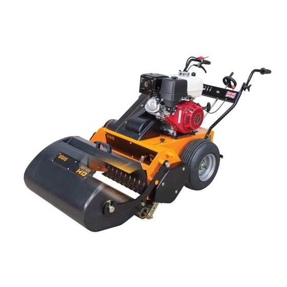
Page 4: Machine Description
OVERVIEW We want you to obtain the best performance from this machine. If, after reading the following instructions, you have any problems please contact SISIS or your local area manager or SISIS dealer. DESCRIPTION The name “ROTORAKE” has become synonymous with effective thatch removal and control. -
Page 5: Important Safety Instructions
Important Safety Instructions READ THE INSTRUCTIONS CAREFULLY AND ALSO THE SEPARATE INSTRUCTION CAUTION DETAILS ON THE ENGINE. Keep in mind that the operators / users of the machinery are responsible for accidents or hazards occurring to themselves, other people and property. People who are unfamiliar with these instructions should not use this machinery. Local regulations or insurance may restrict the age of the operator. -
Page 6: Operating Instructions
Operating Instructions PLEASE READ THESE OPERATING INSTRUCTIONS CAREFULLY BEFORE CAUTION COMMENCING WORK. PREPARATION (Ref. Machine Description) • Thoroughly inspect where the equipment is to be used and remove all hazards and foreign objects including stones, sticks, wire, bones etc. • Thoroughly inspect the machine for missing components, damage and wear. - Page 7 Operating Instructions PLEASE READ THESE OPERATING INSTRUCTIONS CAREFULLY BEFORE CAUTION COMMENCING WORK. ENGAGING DRIVE TO THE REEL (Ref. Machine Description) • Ensure the blades are clear of the ground. This is achieved by adjusting the Depth Control (item 6). • With the engine running, depress Operator Presence Lever (item 3).
-
Page 8: The Reel
The Reel The RR600HD has a quick change reel system. This not only allows damaged or worn blades to be changed easily and quickly, but also makes the machine multi-purpose. REMOVING / REPLACING THE REEL (Ref. Figure 2) • Raise the blades to the maximum clearance from the ground. Figure 2 •... -
Page 9: General Adjustments
General Adjustments HANDLE BARS (Ref. Figure 4) Figure 4 • Slacken the locking knob (item 9) • Rotate the handle around the toothed disc. • Select the required position and retighten the locking knob (item 9) • Repeat for the other handle. COLLECTOR BOX (Ref. - Page 10 General Adjustments F21440 A SECTION (Item 6) This is tensioned by sliding the 90 degree gearbox (item 7) • Slacken the M10 x 30 bolts (17mm spanner) that retain the gearbox (item 7) • Slide the gearbox to the desired position. •...
- Page 11 General Adjustments TINE DRIVE LEVER (ref. fig 4 and fig 6) Figure 6.1 • Remove guards (item 12 and 13, fig 4) (large flat screw driver & 13mm spanner) • Remove split pin and clevis pin (item 6 and 7 fig 6) •...
-
Page 12: Parts Listings
1.01 Common Spares Item No. Part No. Description Quantity SP12002 Throttle Cable G860 / G760 SP12053 Cable Drive SP12052 Wiring Harness F21440 Belt V A37 Cotton (See Drive Axle) SP11036 Belt Z51 (See Drive Axle) F21779 Belt Timing (See Tine Drive) SP11037 Belt B46 Aramid Cored (See Tine Drive) - Page 13 Rivet 3.2 x 6 E1-1061 M6 Spring Washer E1-1065 Spring Washer M12 Square Section F21463 Clevis 8mm GKML 832 F21464 Spring Clevis Pin 8mm F21922 Vibration Mount (Metalastik No 17/1386/01 ) 4 F36000 Serial No Plate (SISIS) F37422 Hinge 602 F37704 Scraper J209243 Handle Grassbox SP01005 Hex Set Screw M8 x 30 SP01006 Button Head M8 x 20 SP01009...
- Page 14 23,22,29,29 3.01 Controls Assembly Item No. Part No. Description Quantity 127434 Red Knob M10 290055 Drive Actuator Assy 290058 Control Lever Assy 290060 Drive Lever Assy 290063 Control Lever Assy 30 Deg 290103 Sensor Angle Plate 290120 Spring Cup 290121 Over Centre Rod D1040 Split Pin 3/32” x 3/4”” D1887 Thackery Washer M12 F21463 Clevis 8mm GKML 832 F21464 Spring Clevis Pin 8mm 176457...
- Page 15 19,32,28 19,32,28 4.01 Roller Assembly Item No. Part Number Description Quantity 290039 Roller Pivot Bush 290040 Roller Arm Assy L.H. 290045 Roller Arm Assy R.H. 290048 Brace End 290049 Roller Scraper 290052 Roller Torsion Bar 290053 Roller Torsion Arm 290054 Torsion Bar Arm 290081 Roller Adj Block 290082 Roller Adjuster Bar 290083 Roller Adj Nut 290084...
- Page 16 30,32,32,27 4,21 4,10 7,29,31 7,29,31 26,34,3 VIEW FROM REAR 31,33,25 33,31,22 30,32,32,27 5.01 Drive & Axle Assembly Item No. Part No. Description Quantity 290062 Torque Strap 290079 Belt Tensioner Post 290080 Spacer Pulley D8154 Grub Screw M8 x 16 D8360 Wheel Nut M12 E1-1065 Spring Washer M12 Square Section E1-1114 Hex Bolt M8 x 65 F20171 Wheel Assy 16x650-8 04 Ply 4 Stud 4” PCD 2 F20527...
- Page 17 1,6,6,4 5.02 Engine & Clutch Assembly Item No. Part Number Description Quantity SP01031 Hex Set Screw M10 x 50 SP01138 Hex Set Screw 3/8” UNF x 1 1/4” SP01133 Hex Bolt 3/8” UNF x 4 3/4” SP02008 Nut M10 Nyloc (T) SP02018 Nut 3/8” UNF Nyloc (T) SP03011 Washer M10 Form A SP03034 Washer M10 Spring Lock SP11033 Clutch CB228 SP15004 GX390 UT2-QX-Q4 290127 Securing Plate * NOTE:- This is a sealed unit, DO NOT open. ROTORAKE JUN ‘13...
- Page 18 6.01 Gear Lever Assembly Item No. Part No. Description Quantity 290110 Gear Lever Assy (600Hd) D1239 Hex Set Screw 1/4” UNF x 3/4” D8485 Ball Joint M8 Ref.R108-M8. F21772 Knob F37454 Gear Shift Lever J20553 Rod M8 x 60 J209085 Bush Oilite AM1216 - 20 SP01029 Shoulder Bolt 12 x 25 M10 SP02006 Nut M8 Nyloc (T) SP02012...
- Page 19 7.01 Grassbox Assembly Item No. Part Number Description Quantity 290070 Grass Collector 24” 290071 Washer 16 x 100 x 3 290072 Grassbox Pivot 290123 Grassbox Decal Plate 290124 Grassbox Front Plate J209064 Handle Plate Grass Box J209243 Handle Grassbox J249062 Mesh J249063 24” Grassbox Edging Strip SP01028 Hex Set Screw M6 x 20 SP02028 Nut M16 Nyloc (T)
- Page 20 13,21 19,21,15 8,15,16,18 12,18,18,17 21,13 16,20,18 17,18 8.01 Tine Drive Assembly Item No. Part No. Description Quantity 290065 Belt Tensioner Assy 290074 Stub Quick Release 290075 Stub Bearing Housing 290076 Layshaft 290077 Belt Tensioner Bush 290078 Pulley Layshaft D8153 Grub Screw M8 x 10 F21150 Bearing Ref. Bpft-5 (25mm Bore) F21779 Timing Belt F22418 Bearing 6008 2RS F37410...
- Page 21 17,24,19 14 28 18,25 21,23,16 19,17 19,17 9.01 Handles Assembly Item No. Part Number Description Quantity 229585 Pivot Block 229754 Clutch Lever Lever 230190 Throttle Lever W.A. 230196 Throttle Plate 290100 Lower Handle Assy (600HD) 290115 Adjuster Lock W.A. E1-1061 M6 Spring Washer E1-1669 Cap Head M6 x 25 F21063 Lock Knob F22019 Handle Grip F36639 Upper Handle R.H.
- Page 22 Item No. Part No. Description Quantity 290091 Guard Clutch 290090 Guard Tine Drive 290092 Guard Axle Drive 290093 Guard Roller Mech SP18017 Decal Depth RR600 SP18016 Decal Tine Drive SP18001 Decal Throttle F35993 Decal Sisis Orange 229599 Decal On / Off 229375 Decal Warning 194946 Chain Case Screw B32903 Decal Union Jack F37466 Decal Gears J209074 Cover Screw F34003 Decal Safety ROTORAKE JUN ‘13...
-
Page 23: Notes
Notes ROTORAKE JUN ‘13...
Need help?
Do you have a question about the ROTORAKE RR600HD and is the answer not in the manual?
Questions and answers