Table of Contents
Advertisement
The Right Fit for Comfort
ECR International LLC
2201 Dwyer Avenue
Utica, NY 13501
e-mail: info@RetroAire.com
An ISO 9001-2000 Certified Company
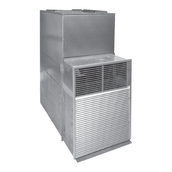
VPRC / VPRH
Single Package Vertical Air Conditioner/Heat Pump
™
Straight cool/Limited Range Heat pump nominal capacities
9,000
12,000
2.6
3.5
Installation, Operation and
Maintenance Manual
18,000
19,000
24,000
5.3
5.6
7.0
P/N 240006980, Rev. I [01/15/2010]
30,000
36,000
Btuh
8.8
10.5
kW
Advertisement
Table of Contents
Troubleshooting

Related Manuals for Retro Aire VPRC


Summary of Contents for Retro Aire VPRC
- Page 1 VPRC / VPRH Single Package Vertical Air Conditioner/Heat Pump ™ Straight cool/Limited Range Heat pump nominal capacities 9,000 12,000 18,000 19,000 24,000 30,000 36,000 Btuh The Right Fit for Comfort 10.5 Installation, Operation and Maintenance Manual ECR International LLC 2201 Dwyer Avenue Utica, NY 13501 e-mail: info@RetroAire.com...
-
Page 2: Table Of Contents
VPRC/VPRH Single Package Vertical Air Conditioner/Heat Pump • Installation, Operation and Maintenance Manual • Contents Table of contents Read This First ..............................3 General Product Information ........................... 4-5 Verify Unit Before Installing — Model Number ....................6 Verify Unit Before Installing — Operational Performance Data ................7 Verify Unit Before Installing —... -
Page 3: Read This First
Have proper overcurrent protection (i.e. time- delay fuse/HACR Breaker) as listed on the Rating Plate. The VPRC/VPRH is backed by EMI and ECR Interna- Tampering with the VPRC/VPRH is dangerous and tional and is tested and rated in accordance with AHRI may result in serious injury or death. -
Page 4: General Product Information
VPRC/VPRH 18, 30 & 36 draw • Wall sleeve transition kit Model 30 only - Needed when installing air through the outdoor coil. a VPRC/VPRH 30 in place of a VPAC/VPHP 30. (See Pg. 15) The Right Fit for Comfort P/N 240006980, Rev. I [01/15/2010]... - Page 5 VPRC/VPRH Single Package Vertical Air Conditioner/Heat Pump • Installation, Operation and Maintenance Manual • General Product Information (continued) Models 09–24 Models 30–36 Supply Supply Outside louver Outside louver Return Return Wall sleeve, Wall sleeve, custom for application custom for application Front —...
-
Page 6: Verify Unit Before Installing - Model Number
InSTALLATIon FoR nEw ConSTRUCTIon Figure 1 Model nomenclature Position number: Chassis coding [verify with rating plate] Product Series VPRC - Straight Cool Unit VPRH - Heat Pump Unit Design Revision: A - Revision Level Cooling Capacity (Btuh): Compressor Code: 09 - 9,000... -
Page 7: Verify Unit Before Installing - Operational Performance Data
ARI certified directory, at www.ahridirectory.org. Due to ongoing product development, designs, specifications, and performance are subject to change without notice. Please consult the factory for further information. Table 1 VPRC/VPRH 09–36 performance data Model Cooling Sensible Heat Pump... -
Page 8: Verify Unit Before Installing - Dimensional/Physical Data
Verify Unit Before Installing — Dimensional/Physical Data IMPORTANT Due to ongoing product development, designs, specifications, and performance are subject to change without notice. Please consult the factory for further information. Figure 2 VPRC/ VPRH dimensions — inches (mm) REAR REAR REAR VPRC/VPRH 20"H X 26"W... -
Page 9: Verify Unit Before Installing — Dimensional/Physical Data
VPRC/VPRH Single Package Vertical Air Conditioner/Heat Pump • Installation, Operation and Maintenance Manual • Verify Unit Before Installing — Dimensional/Physical Data (continued) IMPORTANT Due to ongoing product development, designs, specifications, and performance are subject to change without notice. Please consult the factory for further information. -
Page 10: Verify Unit Before Installing - Responsibilities & Application Limitations
Application limitations This manual has been prepared to acquaint you with the installa- CAUTION tion, operation and maintenance of the VPRC/VPRH SPVU and to Installer — Verify that the ambient temperature conditions provide important safety information in these areas. will be within the limits shown in Figure 1. -
Page 11: Control Box Location
Models 09-24. The control box is only available on the front for Models 30-36. Unless otherwise specified, the VPRC / VPRH control box is factory Figure 3 Control box mounting — Models 09–24 — con- mounted on the front of the unit. Please specify the preferred control trol box can be factory mounted on front (stan- box mounting location when ordering equipment. -
Page 12: Prepare The Enclosure
See Figure 6, Page 13 and Figure 9, Page 15 for details of the platform and wall sleeve installation. The platform height must make the bottom of the VPRC or VPRH chassis flush with the bottom inside edge of the wall sleeve. This means that the platform surface must be ½ inch (13 mm) ABOVE the bottom of the wall sleeve rough opening. - Page 13 Table 4, page 12 for minimum recommended louver studs. opening dimensions. Make sure to account for the extra height of the hydronic coil module, VPRC/VPRH chassis. if used. Control panel (front standard; available on NOTE: The access opening will be in the left left side or right side for models 09–24 only).
-
Page 14: Install The Wall Sleeve
(4 on each away from building side) CAUTION VPRC/VPRH wALL CRoSS SECTIon Verify the wall sleeve opening is square by measuring corner SLEEVE ASSEMBLY oF TYPICAL wALL to corner. Also verify that the platform (if used) is at the Figure 8 correct height and is level with the wall sleeve opening. -
Page 15: Chassis And Wall Sleeve, Typical
• Installation, Operation and Maintenance Manual • Chassis and wall Sleeve, Typical Figure 9 Typical VPRC/VPRH installation, with platform To install the outside louver Install the studs on the inside of the louver. They will pass through the clearance holes in the wall sleeve flange. -
Page 16: Insert Chassis Into Wall Sleeve - Front-Mounted Control Panel Units Only
Supply air connection (return is in front) Install plenum and duct work to supply air connection, all mod- els. Install return air duct work, if applicable (VPRH/VPRC 30–36 only). For models 09–18, an accessory 10-inch round duct collar is Foam gasket available. -
Page 17: Insert Chassis Into Wall Sleeve - Side-Mounted Control Panel Units Only
VPRC/VPRH Single Package Vertical Air Conditioner/Heat Pump • Installation, Operation and Maintenance Manual • Insert Chassis into wall Sleeve — SIDE-MOUNTED CONTROL PANEL UNITS ONLY Inspect foam insulation Figure 12 Foam gasket & weather angles — 09–24 — right-side control panel installations... -
Page 18: Condensate Drain
Models VPRC / VPRH 18 are supplied with a drain stub that must The condensate is slung onto the outdoor coil where it evaporates. -
Page 19: Optional Return Air Access Panel
VPRC/VPRH Single Package Vertical Air Conditioner/Heat Pump • Installation, Operation and Maintenance Manual • optional return air access panel optional return air access panel (with filter) Make sure the installation will provide adequate clearance and access to the control panel. -
Page 20: Hydronic Coil Option - Performance Data
• 20 Ga. Galvanized G90U sheet metal enclosure. The coil package must be centered on top of the VPRC/VPRH • Front, Left or Right side piping connections. chassis. Make sure it is centered over the fan discharge and that •... - Page 21 IMPORTANT Due to ongoing product development, designs, specifications, and performance are subject to change without notice. Please consult the factory for further information. Table 7 VPRC/VPRH hydrocoil specifications (Entering Air Temperature on 70°F, dry bulb/58°F, wet bulb) Entering H2O Head Loss, Ft/H Unit Size...
-
Page 22: Hydronic Coil Option - Assembly And Dimensions
VPRC/VPRH Single Package Vertical Air Conditioner/Heat Pump • Installation, Operation and Maintenance Manual • Hydronic Coil option — Assembly and dimensions Figure 18 Hydronic coil option see Figure 17, page 20 for ordering information (front/right application shown) — 10-inch round (254 mm) duct collar... -
Page 23: Hydronic Coil Option — Assembly And Dimensions
VPRC/VPRH Single Package Vertical Air Conditioner/Heat Pump • Installation, Operation and Maintenance Manual • Hydronic Coil option — Assembly and dimensions (continued) Figure 19 Hydronic coil dimensions Dimensions — Inches (mm) Models 1½ ½ (254) 9–18 (330) (203) (483) (432) -
Page 24: Features
Carrier 50QT/ET replacement (optional) See installation information on page 36. The VPRC/VPRH 09–18 can be used to replace the Carrier 50QT/ET series PTAC and older vertical PTAC’s from other manufacturers . Refer to Figure 1 on page 4 “Options”... -
Page 25: Electrical Connections
Power cord with integral safety protection Single-stage thermostat All VPRC/VPRH units that are cord connected to the power supply Select a thermostat that is compatible with a cooling/single stage are equipped with a power cord with an integral sensor that: heat/heat pump system. -
Page 26: Sequence Of Operation
VPRC/VPRH Single Package Vertical Air Conditioner/Heat Pump • Installation, Operation and Maintenance Manual • Sequence of operation Initial power-up or power restoration Cooling operation When power is applied to the unit, either for the first time or after a If the room temperature is above the thermostat setting, the reversing power failure, the board will initialize itself. -
Page 27: Final Inspection And Start-Up
(Models VPRC/ VPRH 09–24 only) If the condensate is routed to an internal drain, verify that the drain is functioning properly. -
Page 28: Final Inspection And Start-Up
VPRC/VPRH Single Package Vertical Air Conditioner/Heat Pump • Installation, Operation and Maintenance Manual • Final Inspection & Start-up (continued) Figure 22 TEST jumper (selects normal or test mode) NOTICE All wiring should be in accordance with both the National Normal operation Test mode Electric Code (NEC) and the local building codes. -
Page 29: Maintenance And Troubleshooting
Failure to do so could result in severe the air stream. personal injury or death. For optimum performance and reliability of your VPRC / VPRH, Inspect all electrical connections for frayed wires and poor con- nections. ECR International recommends performing the following inspec- tions and maintenance on a monthly basis. -
Page 30: Troubleshooting
VPRC/VPRH Single Package Vertical Air Conditioner/Heat Pump • Installation, Operation and Maintenance Manual • Maintenance and Troubleshooting (continued) Troubleshooting WARNING The troubleshooting procedures below should only be conducted by a qualified technician. Symptom Suggestion No heat or cooling • Check to see if the unit has power and if the thermostat is satisfied. If the thermostat is not satisfied, call your installing contractor or service contractor. -
Page 31: Electrical Specifications
“Indoor Motor Speed Tap Selection Chart” label attached to the 0.1 (3) chassis of the VPRC/VPRH (Table 8). 0.2 (5) Models’ VPRC/VPRH 09–36 motors are factory-wired for the cor- 0.3 (8) responding units as described in the 230V column. Make speed tap 0.1 (3) -
Page 32: Electrical Specifications
NEMA Specifications Non-Locking/Receptacles IMPORTANT Due to ongoing product development, designs, specifications, and performance are subject to change without notice. Please consult the factory for further information. Table 11 VPRC/VPRH 09 electrical specifications Power Supply Indoor Fan outdoor Fan Electric Heat Unit Electrical Ratings Volt —... - Page 33 VPRC/VPRH Single Package Vertical Air Conditioner/Heat Pump • Installation, Operation and Maintenance Manual • Electrical Specifications (continued) Table 13 VPRC/VPRH 18 electrical specifications Power Supply Indoor Fan outdoor Fan Compressor Electric Heat Unit Electrical Ratings Volt — 1–60 Motor Motor...
- Page 34 VPRC/VPRH Single Package Vertical Air Conditioner/Heat Pump • Installation, Operation and Maintenance Manual • Electrical Specifications (continued) VPRC/VPRH 24 Table 15 electrical specifications Power Supply Indoor Fan outdoor Fan Compressor Electric Heat Unit Electrical Ratings Volt — 1–60 Motor Motor...
-
Page 35: Electrical Specifications
VPRC/VPRH Single Package Vertical Air Conditioner/Heat Pump • Installation, Operation and Maintenance Manual • Electrical Specifications (continued) Table 17 VPRC/VPRH 36 electrical specifications Power Supply Indoor Fan outdoor Fan Voltage — Compressor Electric Heat Unit Electrical Ratings Motor Motor 1/60... -
Page 36: Carrier 50Qt/Et Replacement Option - Installation
Single Package Vertical Air Conditioner/Heat Pump • Installation, Operation and Maintenance Manual • Carrier 50QT/ET Replacement option — Installation The VPRC/VPRH can be used to replace the Carrier 50QT/ET series Figure 26 Stamped metal louver PTAC and older vertical PTAC’s from other manufacturers if certain CANNOT be used with the VPRC/VPRH —... -
Page 37: Carrier 50Qt/Et Replacement Option — Installation
The VPRC/VPRH includes an accessory drain stub that must be Install high and low voltage wiring to the VPRC/VPRH unit. Refer installed on the unit’s base on the front side. See Figure 14, Page 18. to the wiring diagram on the unit for wire connections. -
Page 38: Start-Up Report
VPRC/VPRH Single Package Vertical Air Conditioner/Heat Pump • Installation, Operation and Maintenance Manual • Start-Up Report NOTICE The Start-Up Report is provided for use by a qualified service professional Make sure to include the Model Number, Serial Number, and Date of installation. -
Page 39: Notes
VPRC/VPRH Single Package Vertical Air Conditioner/Heat Pump • Installation, Operation and Maintenance Manual • notes Made in USA P/N 240006980, Rev. I [01/15/2010]... - Page 40 ECR International LLC 2201 Dwyer Avenue Utica, NY 13501 e-mail: info@RetroAire.com An ISO 9001-2000 Certified Company The Right Fit for Comfort P/N 240006980, Rev. H [1/13/2010]...
Need help?
Do you have a question about the VPRC and is the answer not in the manual?
Questions and answers