Table of Contents
Advertisement
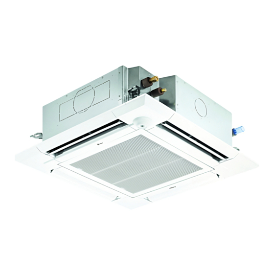
CEILING-RECESSED CASSETTE (FOUR-WAY AIRFLOW)
1. SPECIFICATIONS .................................................................................................................................................... PLFY-3
PLFY-P08NCMU-ER4, PLFY-P12NCMU-ER4, PLFY-P15NCMU-ER4.................................................................. PLFY-3
PLFY-P08NBMU-E2, PLFY-P12NBMU-E2, PLFY-P15NBMU-E2, PLFY-P18NBMU-E2 ....................................... PLFY-4
PLFY-P24NBMU-E2, PLFY-P30NBMU-E2, PLFY-P36NBMU-E2 .......................................................................... PLFY-5
2. EXTERNAL DIMENSIONS ....................................................................................................................................... PLFY-6
3. CENTER OF GRAVITY ............................................................................................................................................ PLFY-8
4. ELECTRICAL WIRING DIAGRAMS ......................................................................................................................... PLFY-9
5. SOUND PRESSURE LEVELS ............................................................................................................................... PLFY-11
5-1. Sound Pressure Levels ................................................................................................................................. PLFY-11
5-2. NC Curves..................................................................................................................................................... PLFY-11
6. TEMPERATURE/AIRFLOW DISTRIBUTIONS ...................................................................................................... PLFY-12
6-1. Temperature Distributions ............................................................................................................................. PLFY-12
6-2. Airflow Distributions ....................................................................................................................................... PLFY-15
6-3. Branch Duct Capacities................................................................................................................................. PLFY-18
7. VENTILATION AIR INTAKE AMOUNT AND STATIC PRESSURE ......................................................................... PLFY-25
7-1. PLFY-P08, 12, 15NCMU-ER4 ....................................................................................................................... PLFY-25
7-2. PLFY-P08, 12, 15, 18, 24, 30, 36NBMU-E2 .................................................................................................. PLFY-25
8. OPTIONAL PARTS ................................................................................................................................................. PLFY-27
8-1. Air Outlet Shutter Plate PAC-SH51SP-E for PLFY-P-NBMU-E2 ................................................................... PLFY-28
8-2. High Efficiency Filter Element PAC-SH59KF-E (MERV 10) for PLFY-P-NBMU-E2 ...................................... PLFY-29
8-3. Multi-function Casement PAC-SH53TM-E for PLFY-P-NBMU-E2 ................................................................ PLFY-29
8-4. i-see Sensor Corner Panel PAC-SA1ME-E for PLFY-P-NBMU-E2 ............................................................... PLFY-30
8-5. Wireless Signal Receiver PAR-SA9FA-E for PLFY-P-NBMU-E2 .................................................................. PLFY-30
8-6. Flange for fresh air intake PAC-SH65OF-E for PLFY-P-NBMU-E2............................................................... PLFY-31
8-7. External Heater Adapter CN24RELAY-KIT-CM3 ........................................................................................... PLFY-32
© 2015 Mitsubishi Electric US, Inc.
PLFY-P-NCMU-ER4, -NBMU-E2 (November 2015)
PLFY-1
Advertisement
Table of Contents

Subscribe to Our Youtube Channel
Related Manuals for Mitsubishi PLFY-P08NCMU-ER4


Summary of Contents for Mitsubishi PLFY-P08NCMU-ER4
-
Page 1: Table Of Contents
8-4. i-see Sensor Corner Panel PAC-SA1ME-E for PLFY-P-NBMU-E2 ............... PLFY-30 8-5. Wireless Signal Receiver PAR-SA9FA-E for PLFY-P-NBMU-E2 ..............PLFY-30 8-6. Flange for fresh air intake PAC-SH65OF-E for PLFY-P-NBMU-E2............... PLFY-31 8-7. External Heater Adapter CN24RELAY-KIT-CM3 ................... PLFY-32 PLFY-P-NCMU-ER4, -NBMU-E2 (November 2015) PLFY-1 © 2015 Mitsubishi Electric US, Inc. - Page 2 Nominal heating cap.*2 Btu/h 6,700 9,000 13,500 17,000 20,000 27,000 30,000 34,000 40,000 54,000 60,000 80,000 108,000 PLFY-P-NCMU-ER4 PLFY-P-NBMU-E2 * Nominal conditions *1, *2 are referred to in the Specification sheet. PLFY-2 PLFY-P-NCMU-ER4, -NBMU-E2 (November 2015) © 2015 Mitsubishi Electric US, Inc.
- Page 3 *Above specification data is subject to rounding variation. Level difference: 0 ft. (0 m) 0 ft. (0 m) *Due to continuing improvement, above specification may be subject to change without notice. PLFY-P-NCMU-ER4, -NBMU-E2 (November 2015) PLFY-3 © 2015 Mitsubishi Electric US, Inc.
-
Page 4: Plfy-P-Ncmu-Er4, -Nbmu-E2
0 ft. (0 m) 0 ft. (0 m) *Due to continuing improvement, above specification may be subject to change without notice. *3 PLFY-P08NBMU-E2 is not compatible with PUMY-P**NHMU/NKMU outdoor units. PLFY-4 PLFY-P-NCMU-ER4, -NBMU-E2 (November 2015) © 2015 Mitsubishi Electric US, Inc. -
Page 5: Plfy-P24Nbmu-E2, Plfy-P30Nbmu-E2, Plfy-P36Nbmu-E2
*Above specification data is subject to rounding variation. Level difference: 0 ft. (0 m) 0 ft. (0 m) *Due to continuing improvement, above specification may be subject to change without notice. PLFY-P-NCMU-ER4, -NBMU-E2 (November 2015) PLFY-5 © 2015 Mitsubishi Electric US, Inc. -
Page 6: External Dimensions
PLFY-P12NCMU-ER4 flared connection flared connection PLFY-P15NCMU-ER4 25-19/32(650) 11-27/32(301) Brand label Air outlet hole Grille Drain hole Auto vane Air intake grille Vane motor 14-27/32(377) Air intake hole 1-3/8(35) 2-5/32(55) PLFY-6 PLFY-P-NCMU-ER4, -NBMU-E2 (November 2015) © 2015 Mitsubishi Electric US, Inc. - Page 7 Refrigerant pipe Flared connection ... 5/8 PLFY-P30NBMU-E2 ... 9.52 3-1/32 11-1/16 11-3/4 3-11/32 PLFY-P36NBMU-E2 Flared connection Refrigerant pipe 15.88 (281) (298) (85) (77) ... 3/8 Flared connection 5/8 (compatible) PLFY-P-NCMU-ER4, -NBMU-E2 (November 2015) PLFY-7 © 2015 Mitsubishi Electric US, Inc.
-
Page 8: Center Of Gravity
125 [4-15/16] PLFY-P30NBMU-ER2 280 [11-1/32] 400 [15-3/4] 105 [4-5/32] PLFY-P30NBMU-E2 PLFY-P36NBMU-ER2 280 [11-1/32] 280 [11-1/32] 400 [15-3/4] 400 [15-3/4] 125 [4-15/16] 125 [4-15/16] PLFY-P36NBMU-E2 280 [11-1/32] 400 [15-3/4] 125 [4-15/16] PLFY-8 PLFY-P-NCMU-ER4, -NBMU-E2 (November 2015) © 2015 Mitsubishi Electric US, Inc. -
Page 9: Electrical Wiring Diagrams
5.Symbols used in wiring diagram above are, :terminal block, :connecter. 6.The setting of the SW2 dip switches differs in the capacity for the detail, refer to the fig:1. 7.Use copper supply wire. PLFY-P-NCMU-ER4, -NBMU-E2 (November 2015) PLFY-9 © 2015 Mitsubishi Electric US, Inc. - Page 10 Main Power supply (Indoor unit:208-230V) LED1 Main power supply power on → lamp is lit Power supply for Power supply for MA-Remote controller LED2 MA-Remote controller on → lamp is lit PLFY-10 PLFY-P-NCMU-ER4, -NBMU-E2 (November 2015) © 2015 Mitsubishi Electric US, Inc.
-
Page 11: Sound Pressure Levels
NC-20 NC-20 15.0 15.0 15.0 continuous noise continuous noise continuous noise 10.0 10.0 10.0 Octave band center frequencies (Hz) Octave band center frequencies (Hz) Octave band center frequencies (Hz) PLFY-P-NCMU-ER4, -NBMU-E2 (November 2015) PLFY-11 © 2015 Mitsubishi Electric US, Inc. -
Page 12: Temperature/Airflow Distributions
(8.8) (8.8) 21(70) 35(95) (6.6) (6.6) 23(73) 31(88) 23(73) 25(77) 27(81) (3.3) (3.3) 23(73) 25(77) 19(66) (9.8) (6.6) (3.3) (9.8) (6.6) (3.3) Floor distance <m(ft)> Floor distance <m(ft)> Ref.:PLFY-NCMU-E_TPD_USDB_70 PLFY-12 PLFY-P-NCMU-ER4, -NBMU-E2 (November 2015) © 2015 Mitsubishi Electric US, Inc. - Page 13 Note : These figures show typical temperature distributions in the conditions above. In the actual installation, they may differ from these figures under the influence of air temperature conditions, ceiling height, cooling/heating load,obstacles,etc. PLFY-P-NCMU-ER4, -NBMU-E2 (November 2015) PLFY-13 © 2015 Mitsubishi Electric US, Inc.
- Page 14 (79) (79) 22(72) (16.4) (13.1) (9.8) (6.6) (3.3) (3.3) (6.6) (9.8) (13.1) (16.4) (16.4) (13.1) (9.8) (6.6) (3.3) (3.3) (6.6) (9.8) (13.1) (16.4) Floor distance <m(ft)> Floor distance <m(ft)> PLFY-14 PLFY-P-NCMU-ER4, -NBMU-E2 (November 2015) © 2015 Mitsubishi Electric US, Inc.
-
Page 15: Airflow Distributions
(8.8) (8.8) 3.0(3.3) 3.0(9.8) 2.0(6.6) (6.6) (6.6) 1.0(3.3) 0.5(1.6) 2.0(6.6) 1.0(3.3) (3.3) (3.3) 0.5(1.6) (13.1) (9.8) (6.6) (3.3) (13.1) (9.8) (6.6) (3.3) Floor distance <m(ft)> Floor distance <m(ft)> Ref.:PLFY-NCMU-E_AFD_USDB PLFY-P-NCMU-ER4, -NBMU-E2 (November 2015) PLFY-15 © 2015 Mitsubishi Electric US, Inc. - Page 16 Note : These figures show typical airflow distributions in the conditions above. In the actual installation, they may differ from these figures under the influence of air temperature conditions, ceiling height, cooling/heating load,obstacles,etc. PLFY-16 PLFY-P-NCMU-ER4, -NBMU-E2 (November 2015) © 2015 Mitsubishi Electric US, Inc.
- Page 17 Note : These figures show typical airflow distributions in the conditions above. In the actual installation, they may differ from these figures under the influence of air temperature conditions, ceiling height, cooling/heating load,obstacles,etc. PLFY-P-NCMU-ER4, -NBMU-E2 (November 2015) PLFY-17 © 2015 Mitsubishi Electric US, Inc.
-
Page 18: Branch Duct Capacities
6. TEMPERATURE/AIRFLOW DISTRIBUTIONS 6-3. Branch Duct Capacities PLFY-18 PLFY-P-NCMU-ER4, -NBMU-E2 (November 2015) © 2015 Mitsubishi Electric US, Inc. - Page 19 6. TEMPERATURE/AIRFLOW DISTRIBUTIONS PLFY-P-NCMU-ER4, -NBMU-E2 (November 2015) PLFY-19 © 2015 Mitsubishi Electric US, Inc.
- Page 20 6. TEMPERATURE/AIRFLOW DISTRIBUTIONS PLFY-20 PLFY-P-NCMU-ER4, -NBMU-E2 (November 2015) © 2015 Mitsubishi Electric US, Inc.
- Page 21 6. TEMPERATURE/AIRFLOW DISTRIBUTIONS PLFY-P-NCMU-ER4, -NBMU-E2 (November 2015) PLFY-21 © 2015 Mitsubishi Electric US, Inc.
- Page 22 6. TEMPERATURE/AIRFLOW DISTRIBUTIONS PLFY-22 PLFY-P-NCMU-ER4, -NBMU-E2 (November 2015) © 2015 Mitsubishi Electric US, Inc.
- Page 23 6. TEMPERATURE/AIRFLOW DISTRIBUTIONS PLFY-P-NCMU-ER4, -NBMU-E2 (November 2015) PLFY-23 © 2015 Mitsubishi Electric US, Inc.
- Page 24 6. TEMPERATURE/AIRFLOW DISTRIBUTIONS PLFY-24 PLFY-P-NCMU-ER4, -NBMU-E2 (November 2015) © 2015 Mitsubishi Electric US, Inc.
-
Page 25: Ventilation Air Intake Amount And Static Pressure
By mounting the optional multi-function casement (PAC-SH53TM-E) to the indoor unit main body, and mounting the optional duct flange(PAC-SH65OF-E) onto it further, fresh exterior air intake can be accomplished. (The mounting of the multi-function casement increases the height of the ceiling plenum by 5-5/16(135mm).) PLFY-P-NCMU-ER4, -NBMU-E2 (November 2015) PLFY-25 © 2015 Mitsubishi Electric US, Inc. - Page 26 1 - inlet 1 - inlet -200(-80) -200(-80) [CMM] [CMM] [CFM] [CFM] Airflow rate Airflow rate Taking air into the unit 50(20) -50(-20) -100(-40) -150(-60) -200(-80) [CMM] [CFM] Airflow rate PLFY-26 PLFY-P-NCMU-ER4, -NBMU-E2 (November 2015) © 2015 Mitsubishi Electric US, Inc.
-
Page 27: Optional Parts
PAC-SA9FA-E PAC-SH65OF-E External heater adapter PLFY-P-NBMU-E2 CN24RELAY-KIT-CM3 PLFY-P-NBMU-E2 Air outlet shutter plate PAC-SH51SP-E Multi-function casement PAC-SH53TM-E High efficiency filter element PAC-SH59KF-E PAC-SH53TM-E is necessary to use with filter PAC-SH59KF-E. PLFY-P-NCMU-ER4, -NBMU-E2 (November 2015) PLFY-27 © 2015 Mitsubishi Electric US, Inc. -
Page 28: Air Outlet Shutter Plate Pac-Sh51Sp-E For Plfy-P-Nbmu-E2
Changing to 1 way is not allowed. Material: Foamed polyethylene + foamed urethane, color: Black Item Shutter plate Insulator Quantity Shape Detailed installation information should be referred to its Installation Manual. PLFY-28 PLFY-P-NCMU-ER4, -NBMU-E2 (November 2015) © 2015 Mitsubishi Electric US, Inc. -
Page 29: High Efficiency Filter Element Pac-Sh59Kf-E (Merv 10) For Plfy-P-Nbmu-E2
Item Decoretive panel securing bracket Insulator A for Decorative panel Insulator B for Decorative panel Quantity With insulator Shape Detailed installation information should be referred to its Installation Manual. PLFY-P-NCMU-ER4, -NBMU-E2 (November 2015) PLFY-29 © 2015 Mitsubishi Electric US, Inc. -
Page 30: I-See Sensor Corner Panel Pac-Sa1Me-E For Plfy-P-Nbmu-E2
The corner panel(the other side of refrigerant piping) is changed for the wireless signal receiver. Item Wireless signal receiver Quantity Shape Detailed installation information should be referred to its Installation Manual. PLFY-30 PLFY-P-NCMU-ER4, -NBMU-E2 (November 2015) © 2015 Mitsubishi Electric US, Inc. -
Page 31: Flange For Fresh Air Intake Pac-Sh65Of-E For Plfy-P-Nbmu-E2
The flange for fresh air intake is installed in the Multi-function casement(PAC-SH53TM-E) or indoor unit. Item Duct flange Insulator Screw Quantity M4x10 Shape Detailed installation information should be referred to its Installation Manual. PLFY-P-NCMU-ER4, -NBMU-E2 (November 2015) PLFY-31 © 2015 Mitsubishi Electric US, Inc. -
Page 32: External Heater Adapter Cn24Relay-Kit-Cm3
Control board 88H --------- Electromagnetic contactor CN24 Fan speed setting cable External output cable Item with resistance Quantity Shape Refer to the Installation Manual for wiring and installation details. PLFY-32 PLFY-P-NCMU-ER4, -NBMU-E2 (November 2015) © 2015 Mitsubishi Electric US, Inc. - Page 33 PLFY-P-NCMU-ER4, -NBMU-E2 (November 2015) PLFY-33 © 2015 Mitsubishi Electric US, Inc.
Need help?
Do you have a question about the PLFY-P08NCMU-ER4 and is the answer not in the manual?
Questions and answers