Table of Contents
Advertisement
Advertisement
Table of Contents

Subscribe to Our Youtube Channel
Related Manuals for Avid Technology X0 Trail


Summary of Contents for Avid Technology X0 Trail
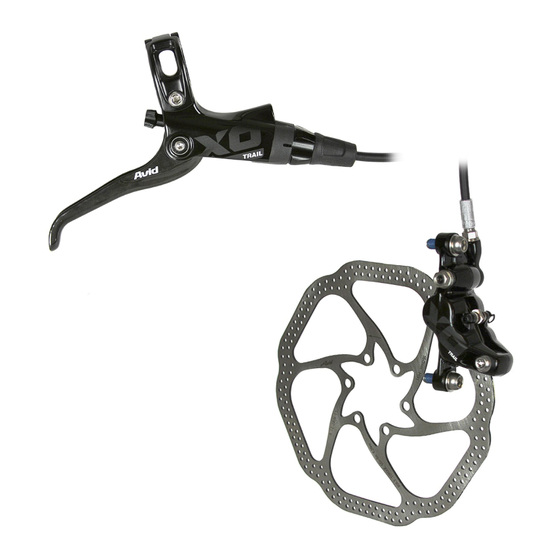
- Page 1 2012 X0 Trail ™ Service Manual GEN.0000000004233 Rev A © 2012 SRAM LLC...
- Page 2 SRAM LLC WARRANTY ExTENT of LiMiTEd WARRANTY Except as otherwise set forth herein, SRAM warrants its products to be free from defects in materials or workmanship for a period of two years after original purchase. This warranty only applies to the original owner and is not transferable. Claims under this warranty must be made through the retailer where the bicycle or the SRAM component was purchased.
-
Page 3: Table Of Contents
TAblE oF CoNTENTS bRAkE SERviCE ovERviEW................................5 lEvER ovERhAul .................................... 6 LEvER EXPLODED vIEW ..........................................6 PARTS AND TOOLS NEEDED FOR SERvICE ................................... 6 CAlipER ovERhAul ..................................14 CALIPER EXPLODED vIEW ..........................................14 PARTS AND TOOLS NEEDED FOR SERvICE ..................................14 TROUBLESHOOTING ............................................15 hoSE lENgTh AdjuSTMENT ................................21 PARTS AND TOOLS NEEDED FOR SERvICE .................................. - Page 4 SAfETY fiRST! At SRAM, we care about YOU. Please, always wear your safety glasses and protective gloves when servicing your products. Protect yourself! Wear your safety gear!
-
Page 5: Brake Service Overview
S A F E T y i N S T R u C T i o N S • Always wear safety glasses and nitrile gloves when working with DOT fluid. • Place an oil pan on the floor underneath the area where you will be working on the brake. • Used DOT fluid should be recycled or disposed of in accordance to local and federal regulations. -
Page 6: Lever Overhaul
l E v E R o v E R h A u l l E v E R E x p l o d E d v i E W Tooled reach adjust models A. Hose stop F. Lever blade B. - Page 7 Use a T25 TORX® wrench to remove the brake clamp bolt from the Discrete clamp, MMX, or XLoc™ (XLoc requires removal of the shifter). Remove the brake lever from the handlebar. Pull the hose boot off the compression nut and slide it down the hose. discrete Clamp Use an 11 mm open end wrench to hold the hose stop in place and use an 8 mm flare nut wrench to remove the hose compression nut.
- Page 8 Use a pick to disengage the return spring eyelet from the spring anchor tab. Spring Return anchor spring eyelet Turn the reach adjuster counter-clockwise until the adjuster disengages from the pushrod. Tooled reach adjust models: Use a 3 mm hex wrench to turn the reach adjuster.
- Page 9 Use the pliers to apply downward pressure to the lever body and remove the snap ring. Remove the piston/bladder assembly. C A u T i o N - E y E h A z A R d Do not look directly into the lever body while performing this step. The internal piston/spring assembly is preloaded and will come out of the lever body quickly, which can result in injury.
- Page 10 Insert the piston/bladder assembly into the lever body with the keyed section of the piston retainer oriented toward the opening in the lever body. Use the snap ring pliers to push the piston/bladder assembly into the lever body, and secure the snap ring in its groove. Orient the snap ring eyelets opposite the opening in the lever body.
- Page 11 Insert the lever blade into the lever body. Thread the reach adjuster onto the pushrod and turn it clockwise an additional 5-6 complete turns. Tooled reach adjust models: Use a 3 mm hex wrench to turn the reach adjuster. lever overhaul...
- Page 12 Use the angled tip of a pick to lift and fasten the eyelet of the lever return spring onto the spring anchor tab on the snap ring. Use a T10 TORX® wrench to install the pivot bolts into both sides of the lever.
- Page 13 Thread the compression nut into the lever body until it stops. Hold the hose stop secure with an 11 mm open end wrench and use a torque wrench with an 8 mm flare nut crowfoot to tighten the compression nut to 4.9-5.4 N∙m (43-48 in-lb). Spray isopropyl alcohol on the lever and clean it with a rag.
-
Page 14: Caliper Overhaul
C A l i p E R o v E R h A u l C A l i p E R E x p l o d E d v i E W A. E-clip G. Banjo fitting B. Piston seals H. -
Page 15: Troubleshooting
T R o u b l E S h o o T i N g ‘Sticky’ or slow brake pad return feel/excessive lever throw Before completely disassembling your caliper, it’s worth trying to loosen the sticky pistons. Try the following: Clamp the bicycle in a bicycle work stand. - Page 16 Use a 5 mm hex wrench to remove the brake caliper from the fork or frame and remove the caliper mounting bracket and hardware from the caliper. Set aside in the correct order. Remove the e-clip from the pad retainer bolt. Use a 2.5 mm hex wrench to remove the pad retainer bolt from the caliper.
- Page 17 Caliper Piston Removal: Place one of the caliper halves, piston side down, on a soft rubber mat or a small section of inner tube on a flat surface. Insert a rubber-tipped blow gun chuck nozzle into the banjo port. While firmly pushing against the caliper half and chuck nozzle, squeeze the air chuck to force air into the banjo port and unseat the pistons from the caliper.
- Page 18 Inspect the caliper pistons for damage and replace them if necessary. Apply a small amount of DOT 5.1 fluid to the circumference of each piston. Reinstall the pistons into each half of the caliper body. Wipe any excess fluid from the caliper halves. There are two larger diameter pistons and two smaller diameter pistons.
- Page 19 Reassemble the caliper halves. Insert the banjo bolt through the outboard caliper half. Apply a small amount of DOT 5.1 fluid to the caliper o-ring and install it onto the banjo bolt. Place the inboard caliper half onto the banjo bolt. Place the banjo fitting onto the threads of the banjo bolt.
- Page 20 Insert the Bleed Block into the caliper in place of the brake pads. You will need to bleed your brakes before reinstalling the brake pads. Click here for detailed brake pad removal instructions Spray isopropyl alcohol on the caliper and clean it with a rag. visually check your work.
-
Page 21: Hose Length Adjustment
h o S E l E N g T h A d j u S T M E N T S A F E T y i N S T R u C T i o N S • Always wear safety glasses and nitrile gloves when working with DOT fluid. • Place an oil pan on the floor underneath the area where you will be working on the brake. - Page 22 For models with a compression nut and a hex hose stop: Use an 11 mm open end wrench to hold the hose stop in place and use an 8 mm flare nut wrench to unthread the compression nut. For models with a compression nut only: Use an 8 mm flare nut wrench to unthread the compression nut.
- Page 23 Apply Avid DOT Grease to the threads of a new hose barb, the compression fitting outer surfaces and compression nut threads. While holding the hose firmly, use a T10 TORX® to thread the hose barb into the end of the hose until it is flush. Slide a new compression fitting over the end of the hose with the new hose barb.
- Page 24 For models with a compression nut and a hex hose stop: While continuing to push the hose into the hose stop, use an 11 mm open end wrench to hold the hose stop in place and use an 8 mm flare nut wrench to tighten the compression nut to the proper torque.
-
Page 25: Brake Bleed Procedure
b R A k E b l E E d p R o C E d u R E Avid brakes are the most powerful and precise hydraulic brakes on the market. A key reason behind this is the ability to optimize brake performance with a perfect bleed. - Page 26 bleeding Avid brakes forces air bubbles out of the system. We recommend that you bleed your brakes at least once a year to ensure optimal performance. if you ride frequently or in aggressive terrain, you should bleed your brakes more often. When bleeding brakes, you may notice discoloration of the old fluid as it exits the system into the syringe at the lever.
- Page 27 For models with Contact point Adjustment and a rotating bleed port screw located on the contact point adjuster: rotate the adjuster in the direction opposite the arrow until it stops, then rotate the adjuster back just enough to place the bleed screw at its highest point.
- Page 28 Hold both syringes upright. Gently push on the caliper syringe plunger to move fluid from the caliper syringe into the lever syringe until the lever syringe is increased to 1/2 full and the caliper syringe is decreased to 1/4 full. You should see bubbles form in the lever syringe.
- Page 29 Once the large bubbles at the caliper have stopped, apply a small amount of pressure on the syringe plunger and slowly let the pressure extend the brake lever you have been holding with your finger. If you fastened the lever with a zip-tie or rubber bands, remove these first but keep the lever pulled in with your finger, then apply pressure on the syringe plunger.
- Page 30 Once the large bubbles at the lever have stopped, apply a small amount of pressure on the syringe plunger then remove the syringe and reinstall the bleed port screw. There will be a small amount of excess DOT fluid that spills out as you remove the syringe and reinstall the bleed port screw, this is normal.
-
Page 31: Pad Replacement Instructions
p A d R E p l A C E M E N T i N S T R u C T i o N S Remove the e-clip from the pad retainer bolt. Use a 2.5 mm hex wrench to remove the pad retainer bolt from the caliper. E-clip Place a flat blade screwdriver between the brake pads, then carefully rock it back and forth to push the pistons completely into... -
Page 32: Disc Brake Pad And Rotor Bed-In Procedure
d i S C b R A k E p A d A N d R o T o R b E d - i N p R o C E d u R E All new brake pads and rotors should be put through a wear-in process called ‘bed-in’. The bed-in procedure, which should be performed prior to your first ride, ensures the most consistent and powerful braking feel along with the quietest braking in most riding conditions. - Page 33 www.sram.com...
Need help?
Do you have a question about the X0 Trail and is the answer not in the manual?
Questions and answers