Table of Contents
Advertisement
Quick Links
DNP
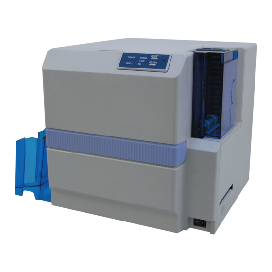
DIRECT DYE SUBLIMATION PRINTER
SPECIFICATIONS
Item
Recording Mode Dye sublimation printing
Paper Feed Mode
Automatic feeding
Recording Density
300 dpi
Color
256 gradations per color
Printing Time
Approx. 20 seconds (Single-sided printing in
standard mode for all of YMC, Resin K and
OP, encoding time excluded)
Interface
USB2.0 Hi-Speed (USB-IF certified product)
Usage
Temperature : 15°C – 30°C
Environment
Humidity
Storage Environment Temperature : -15°C – 55°C
Humidity
Power Supply
AC 100 – 120 V (tolerance ±10%)
AC 220 – 240 V (tolerance ±10%)
Power
1.8 A (100 V)
Consumption
0.9 A (200 V)
Mass
12kg and below (excluding MG/IC encoder)
15kg and below (including MG/IC encoder)
Dimension
Approx. 299 (W) x 311 (D) x 308 (H)mm
Specifications and appearance of this unit may be changed for the purpose of product improvement without
prior notice.
SERVICE MANUAL
CX-120
Description
: 35% – 70%
(without condensation)
: 20% – 80%
Item
Accessories
Power Cord : AC120V (Dark gray: North America) 1
Instruction Manual : English CD
Startup Guide : English
Cleaning Card
Protection Card
USB Cable (1.5 m)
Consumable
Cleaning Card 10 pcs / set (CX-120CC1)
Items
Cleaning Kit (CX210-CKIT1)
Cleaning Unit (CX-120CL1)
Thermal Head (CX-120HD1)
Ink Ribbon
YMCKO
YMCKOK 600 screen pages (CY-16K-60)
Optional Items
Card Cassette (CX-120HP1)
Hand Gloves
M Size (U105-M)
L Size (U105-L)
Laminator Unit (CL-500)
Description
AC200V (Europe)
1
1
1
1
1
1
750screen pages (CY-15C-75)
KAS-T089
June 2005
Advertisement
Table of Contents

Related Manuals for DNP CX-120


Summary of Contents for DNP CX-120
-
Page 1: Service Manual
SERVICE MANUAL DIRECT DYE SUBLIMATION PRINTER CX-120 SPECIFICATIONS Item Description Item Description Recording Mode Dye sublimation printing Accessories Power Cord : AC120V (Dark gray: North America) 1 Paper Feed Mode Automatic feeding AC200V (Europe) Recording Density 300 dpi Instruction Manual : English CD... - Page 2 Operation Environment ..........18 Update of USB Driver - Windows2000 ......15 Installation of USB Driver - WindowsXP ...... 19 Update of CX-120 Status Monitor ....... 18 Installation of USB Driver - Windows2000 ....20 Uninstalling Software ............19 Installation of CX-120 Status Monitor ......21 Deletion of USB Driver - WindowsXP ......
-
Page 3: Table Of Contents
SERVISE MANUAL MG / IC ENCODING UNIT ..........23 1. MG/ IC ENCODER SPECIFICATIONS ....23 MODEL NAME ..............1 1.1 Magnetic Encoding Unit Specifications .... 23 1. DETAILED SPECIFICATIONS ........1 1.2 General Equipment Specifications ....23 BLOCK DIAGRAM .............. 2 2. -
Page 4: Important Safety Precautions
SAFETY PRECAUTION Important Safety Precautions Prior to shipment from the factory, JVC products are strictly inspected to conform with the recognized product safety and electrical codes of the countries in which they are to be sold. However, in order to maintain such compliance, it is equally important to implement the following precautions when a set is being serviced. - Page 5 SAFETY PRECAUTION • Safety Check after Servicing Examine the area surrounding the repaired location for damage or deterioration. Observe that screws, parts and wires have been returned to original positions, Afterwards, perform the following tests and confirm the specified values in order to verify compliance with safety standards.
-
Page 6: Model Name
BLOCK DIAGRAM MODEL NAME Alphabets and numerals after the model name are used to distinguish the different regions of use and specifications. ID Label: CX-120*-#-DN 1. DETAILED SPECIFICATIONS *1 : * Portion — Region of use U ... North America (100 – 120 V) E ... -
Page 7: Block Diagram
BLOCK DIAGRAM BLOCK DIAGRAM 1. BLOCK DIAGRAM OF ENTIRE UNIT Head Inlet BLEED No Card T pos Head Exit Inter Lock CAMP CB Head Ink motor Power Switch DAD PCB Drive PCB Hopper Motor Turn Head Turn over motor over Print motor feed... -
Page 8: Connection Diagram
BLOCK DIAGRAM 2. CONNECTION DIAGRAM Head PWB Inlet CN53 CN52 KWS0723 KWS0724 KWR18418 BLEED CN100 No Card Tpos Head Ink1 Ink2 Exit Inter LocK CN101 CAMPWB Head FAN Ink motor KWS0725 Power Switch CN82 CN99 CN87 CN95 CN88 CN84 CN85 CN90 CN94 CN93 KWS0726... -
Page 9: Layout Of Key Parts
LAYOUT OF KEY PARTS LAYOUT OF KEY PARTS 1. FRONT: HEAD, FEED ROLLER, TURNOVER UNIT AND SENSORS Ink Ribbon Position Sensor Interlock Switch (Head Exchange Door) Thermal Head and Press Mechanism Turnover Unit Origin Sensor Interlock (Printer Door) Head Cooling Fan RF-ID Unit Cleaning Roller Detection Sensor Card Supply Roller... -
Page 10: Rear: Motor, Fan And Sensors
LAYOUT OF KEY PARTS 2. REAR: MOTOR, FAN AND SENSORS Card Feed Motor in Turnover Unit Head Press Cam Position Detection Sensor Card Turnover Motor Ink Ribbon FG Sensor Head Press Cam Motor Ink Ribbon Winding Motor Card Feed Motor Rear Fan Card Supply Motor MG / IC Unit (Optional) -
Page 11: Boards And Power Sources
LAYOUT OF KEY PARTS 3. BOARDS AND POWER SOURCES Front Board DAD Board Drive Board Main Board AC Inlet Power Supply Unit... -
Page 12: Mg / Ic Unit
LAYOUT OF KEY PARTS 4. MG / IC UNIT MG Head Carriage Motor IC Contact (ISO MG Type) IC Contact (JIS MG Type) MG Head Assembly IC Contact Pressure Solenoid (JIS MG Type) MG Head Origin Sensor (For ISO) MG Head Origin Sensor (For JIS) -
Page 13: Dismantling Key Parts
DISMANTLING KEY PARTS DISMANTLING KEY PARTS 1. LAYOUT DIAGRAM DURING MAINTENANC The rear panel can be opened for maintenance by re- moving the following screws. QYSDSP3006N Loosen the screws QYSDSP4008N Loosen the screws 2. DISMANTLING EXTERNAL PARTS AND REFERENCE WIRING DIAGRAM 2.1 Dismantling the Top Cover KJJ46697-001x2 QYSDSP... -
Page 14: Reference Wiring Diagram
DISMANTLING KEY PARTS 2.3 Reference Wiring Diagram... -
Page 15: Dismantling The Mg / Ic Unit
DISMANTLING KEY PARTS 3. DISMANTLING THE MG / IC UNIT Front Screw Fitting Clamp Figure 1 (MAIN) MG/IC To J3 QYSPSPH3006N x2 MAIN Front Screw Fitting To CN8 Figure 1 Hang belt on the gear. (MG/IC) G.No.004 G.No.003 QYSPSPH3006N G.No.002 Be careful not to catch the wires when... -
Page 16: Dismantling Boards And Power Supply Units
DISMANTLING KEY PARTS 4.2 Dismantling Boards and Power Supply Units 4.2.1 Dismantling the DAD Board CN73 CN72 CN79 (TPS239-1) CN77 DAD PWB CN78 CN71 4.2.2 Dismantling the Drive Board Figure 2 Clamp Connect to CN93 of the Interlock PWB CN93 Figure 2 Clamp KWS0728-001... -
Page 17: Dismantling The Main Board
DISMANTLING KEY PARTS 4.2.3 Dismantling the Main Board KWS0729-001 Clamp Clamp Figure 1 MAIN PWB Wiring at QYSPSPH Figure 2 PWB BKT SA PWB BKT’s End (TPS237-1) 3006N x3 KJJ46271-003x4 PWB BKT SA Figure 2 Insert power supply wiring into the clamp CN21 Clamp CN70... -
Page 18: Dismantling The Motor Assembly
DISMANTLING KEY PARTS 5. DISMANTLING THE MOTOR ASSEMBLY 5.1 Dismantling the Turn Motor Assembly Before installing the turn motor unit, turn the turnover unit and ensure that the wire is located on the left as shown in the diagram. Figure 2 Lead the wire from underneath the card edge holder Clamp the wire that is... -
Page 19: Dismantling The Dc Motor
Figure 4 QYSPSPL 3004N x2 CN94 KJJ46271-003x2 CN99 KJJ46271-003 CL SENSOR (KEP4103-Q) QYSPSPL 3004N x2 Labeled Face CX-120-M04 (184) Figure 4 QYREE4000X Clamp CX-120-M04 Labeled Face Figure 5 6. DISMANTLING THE TURNO- 7. DISMANTLING THE HEAD VER UNIT PRESS ASSEMBLY... -
Page 20: Mechanical Operations
MECHANICAL OPERATIONS MECHANICAL OPERATIONS Operations of the card printer mechanism can be divided into 5 types, namely initialize operation, feed operation, print operation, MG operation and IC operation. Commands from the host are made up using a combination of these operations. For example, the actual print command is realized via the serial execution of a feed operation from the hopper to the print position and a print operation. - Page 21 MECHANICAL OPERATIONS Optional Turnover Operation The diagram below indicates the card orientation in the case of a feed operation without the optional turnover operation. If the optional turnover operation is added to the feed command, orientation of the card at the feed destination as shown below will be reversed.
-
Page 22: Print Operation
MECHANICAL OPERATIONS 3. PRINT OPERATION Duplex printing is a combination of this print operation and a feed operation with an optional turnover operation. Mechanical Operation 1 Ink Ribbon Winding Motor RF-ID Board Card Feed Motor in Turnover Unit Ink Ribbon FG Sensor Card Turnover Motor Ink Ribbon Position Sensor Origin Sensor in Turnover Unit... - Page 23 MECHANICAL OPERATIONS Mechanical Operation 2 Head Press Mechanism Ink Ribbon FG Sensor Card Turnover Motor Ink Ribbon Winding Motor Card Discharge Sensor Card Feed Motor in Turnover Unit Head Press Motor Head Press Cam Card Feed Sensor Card Feed Motor Head Press Cam Position Detection Sensor Sequence Diagram Print Operation (YMCKO Ink)
-
Page 24: Mg Operation
MECHANICAL OPERATIONS 4. MG OPERATION ISO and JIS magnetic stripes are located on opposite faces of the card. Position of this card printer’s magnetic head is fixed, and therefore different models are used respectively for the ISO and JIS specifications. : Magnetic head moves from back to front to perform recording/playback of magnetic data. -
Page 25: Troubleshooting
TROUBLESHOOTING TROUBLESHOOTING 1. ERROR CODE LIST AND CORRESPONDING SERVICING PROCEDURES Display Message on CX-120 Countermeasures Countermeasures Status Monitor (User) (Servicing) Printer initialization has failed. The laminator may not Check to ensure that the Change cable if cable for be in a ready status, or connection with laminator may... -
Page 26: Maintenance
Head Assembly 120,000 Paths Number of printed ink panels on 24000 screen pages, by the Printer Setting screen of the Y, M, C, K, O inkribbon. CX-120 Maintenance Tool. KJV46484-002 Fan Filter Approx. 2 yrs Varies with environment CX-120CL1 Cleaning Roller Assembly Approx. -
Page 27: Items For Adjustment
ITEMS FOR ADJUSTMENT ITEMS FOR ADJUSTMENT 1. POWER SUPPLY VOLTAGE ADJUSTMENT Adjustments when replacing the power supply unit Upon replacing the power supply unit, perform the following to adjust the voltage. Location to Perform Adjustment VR to Adjus Adjusted Voltage Value Between Pin 8 of CN2 (5V) and Pin 5 of CN2 (GND) 5.05V —... -
Page 28: Mg / Ic Encoding Unit
MG / IC ENCODING UNIT MG / IC ENCODING UNIT 1. MG / IC ENCODING SPECIFICATIONS 1.1 Magnetic Encoding Unit Specifications 1) Compliant Card (1) ID-1 type magnetic striped card in compliance with the ISO7810/7811/7812 standards • Coercivity Hi-co 2750Oe (High coercivity) Lo-co 300Oe (Low coercivity) •... -
Page 29: Block Diagram
MG / IC ENCODING UNIT 2. BLOCK DIAGRAM 2.1 MG / IC Unit Block Diagram Serial Port MAIN PWB DRIVE PWB CNTL Printer MG/IC PWB CPLD LC4032V MG Encode Solenoid Motor Drive Curcuit Drive (Only producton line use) C-PWB B-PWB CN12 Motor CN11... -
Page 30: Connection Diagram
MG / IC ENCODING UNIT 2.2 Connection Diagram... -
Page 31: Replacing The Mg / Ic Encoding Unit
MG / IC ENCODING UNIT 3. REPLACING THE MG / IC ENCODING UNIT 3.1 Repair Services Replacement is possible only for the entire MG encoding unit. The unit has to be sent back to our plant for servicing of internal components. 3.2 Replacement Procedure Insert the MG unit into the printer. - Page 32 MG / IC ENCODING UNIT Perform read/write tests accordingly from the MG tests in the (Self Test of the CX-120 Maintenance Tool). Apply developing solution to the magnetic media of the magnetic card that is used for the test, such that the tracks on the magnetic stripe become visible to the eyes.
-
Page 33: Dip Switch
MG / IC ENCODING UNIT 3.3 DIP Switch IC Card Stop Position Adjustment (IC Contact Position) No.3 No.2 No.1 Adjustment Value (mm) Specifications IC Card Stop Position Adjustment STX Position Adjustment IC Card Stop Position Adjustment No.4 Direction of Adjustment + Direction –... -
Page 34: Assembly Diagram And Parts List
ASSEMBLY DIAGRAM AND PARTS LIST ASSEMBLY DIAGRAM AND PARTS LIST 1. CAUTIONS Parts with the “!” mark are items important for safety reasons. To ensure safety, always ensure to use only designated parts during replacement. We do not supply parts that are not listed in the Parts List or those indicated as “–” in the chart. Parts for maintenance purposes are sold at their standard price (exclusive of tax). -
Page 35: Assembly Diagram And Parts List
ASSEMBLY DIAGRAM AND PARTS LIST 2. ASSEMBLY DIAGRAM AND PARTS LIST Exploded Head Press Assembly Diagram QYREE7000X Check to ensure that the spring fits properly into the semi-circular lugs at the upper and lower ends. CM45358-003 Insert the spring between the steel plates Ensure that the steel plate fits in properly at both the left and right... -
Page 36: Exploded Frame Assembly Diagram
ASSEMBLY DIAGRAM AND PARTS LIST Exploded Frame Assembly Diagram QYREE 3000X REAR SA Figure 1 Caution: Install perpendicularly (NG if less than 90˚) Figure 2 QYSPSPH FRONT SA 3006N Not required when QYSPSPH Turn by 90˚ upon inserting an MG unit is to be 3006Nx2 installed and fasten accordingly. -
Page 37: Exploded Frame (Center Frame) Assembly Diagram
ASSEMBLY DIAGRAM AND PARTS LIST Exploded Frame Assembly (Center Frame) Diagram KJJ46271 -003x3 KJJ46271 -003x2 FRONT SA Figure 2 KJJ46271-003 PLATE RU SA Figure 3 KJJ46271 -003x2 REAR SA KJJ46271 Fasten screw at KJJ46271 the end with the D cut. -003x2 Figure 1 -003x2... -
Page 38: Exploded Bottom Assembly Diagram
ASSEMBLY DIAGRAM AND PARTS LIST Exploded Bottom Assembly Diagram KWS0723-001 QYSPSPH4008N Follow the diagram for wiring of wires from the power switch and remove any slacks QYWBS KWS0724-001 438505N Figure 2 QYSPSPH3006Nx2 • Ensure that the faston terminals Fasten the screw such are firmly inserted. -
Page 39: Exploded Turnover Unit Assembly Diagram
ASSEMBLY DIAGRAM AND PARTS LIST Exploded Turnover Unit Assembly Diagram Install by sliding it from underneath the spring Install according to procedure from SPRING x2 KJJ46271 CARD GUIDE x2 Sensor SA -003 x2 QYREE PRESS ROLLER 3000X Figure 1 Sensor SA (Figure 1) T. -
Page 40: Exploded Turn Motor Assembly Diagram
Long the steel plate able to move up and down. KJJ46271 -003x2 (6pins) (KEP4103-H) CX-120-M02 CAM SENSOR There is limited space for the sensor. QYREE Be careful not to damage 4000X it when inserting. -
Page 41: Exploded Mechanical Assembly (Bottom) Diagram
ASSEMBLY DIAGRAM AND PARTS LIST Exploded Mechanical Assembly (Bottom) Diagram CN90 KWS0736-001 Guide wire through the bush Guide wire through hole of the steel plate QYSPSPL 3006Nx2 (KEP4103-E) QYREE 5000X Figure 3 FEED IN SENSOR KJJ46271-003x2 KJJ46271-003x2 QYREE QYREE 5000X 5000X KJJ46271-003 QYREE... -
Page 42: Exploded Mechanical Assembly (Feed 1) Diagram
ASSEMBLY DIAGRAM AND PARTS LIST Exploded Mechanical Assembly (Feed 1) Diagram Install according to procedure from PLATEN ROLLER Insert the plate spring through the gap of the guide 5 PIN GUIDE F FEED ROLLER Shaft of Platen Roller 3 SMALL FEED ROLLER Figure 1 Figure 2 2 Card Guides... -
Page 43: Exploded Mechanical Assembly (Feed 2) Diagram
CX-120-SHLD KJJ46271-003 KJJ46271-003 QYSDSF 3008N Install according to procedure from Insert CX-120-SHLD into the rear frame (Do not fasten) Clamp Tighten screws for 10 Card Guide L and 11 Card Guide RR Tighten screw for 12 Pin Guide R KJJ46271-003... -
Page 44: Exploded Mechanical Assembly (Turn Unit) Diagram
ASSEMBLY DIAGRAM AND PARTS LIST Exploded Mechanical Assembly (Turn Unit) Diagram Procedure for installing discharge roller Install Press Roller SA (x 2) Install Roller SA Install Spring (x 2) Figure 1 PRESS ROLLER SA QYREE QYREE 5000X x2 4000X QYREE 5000X Figure 1 2 sets used... -
Page 45: Exploded Mechanical Assembly (Press) Diagram
ASSEMBLY DIAGRAM AND PARTS LIST Exploded Mechanical Assembly (Press) Diagram Pay attention Figure 4 Ink Sensor SA Wire Ring to position of Install only after installing the spring Guide the wire of the ink sensor the head press assembly. SA in such a way to avoid the hole indicated by the arrow, followed by clamping it. -
Page 46: Exploded Mechanical Assembly (Wind) Diagram
ASSEMBLY DIAGRAM AND PARTS LIST Exploded Mechanical Assembly (Wind) Diagram Upon Installation of the T.UP Bobbin Procedure for Encoder Assembly Figure 3 Insert Encode Disk and Gear Assembly together into the shaft and fasten accordingly KJJ46271-003 Tighten screw for Encode Board Install before doing so for the bobbin QYSPSPH... -
Page 47: Exploded Mechanical Assembly (Motor) Diagram
(KEP4103-D) Ensure that the wire is CL SENSOR not in contact with the spring Figure 2 (KEP4103-Q) Clamp QYSPSPL 3004N x2 Labeled Face CX-120-M04 Figure 4 (184) QYREE4000X Clamp CX-120-M04 Check to ensure Clamp Clamp that the wire of the... -
Page 48: Exploded Mechanical Assembly (Fan) Diagram
QYSPSP 4008N x3 QYSPSPH 4020Nx2 Shaft and Face 1 Check part number CX-120 FAN1 Tighten screw on the flat surface of the shaft (126) QYYASPW4006F Lock screws upon tightening. Perform secondary tightening (Torque: 1.96 - 2.35 N.m) -
Page 49: Exploded Mechanical Assembly (Turn Motor) Diagram
ASSEMBLY DIAGRAM AND PARTS LIST Exploded Mechanical Assembly (Turn Motor) Diagram Before installing the turn motor unit, turn the turn unit and ensure that the wire is located on the left as Check operation of the roller shown in the diagram. (Roller can be lifted using a hand and Check operation of the head press returns to the original position once released) -
Page 50: Exploded Pwb Assembly (Dad) Diagram
ASSEMBLY DIAGRAM AND PARTS LIST Exploded PWB Assembly (DAD) Diagram Clamp wires of CN71 and CN72 Figure 1 CN73 CN72 CN79 (TPS239-1) CN77 DAD PWB CN78 CN71 Guide only the wire of the CN77 Clamp wires of CN71 and CN72 motor through the rear of the board Guide only the wire of the CN77 CN73... -
Page 51: Exploded Pwb Assembly (Drive) Diagram
ASSEMBLY DIAGRAM AND PARTS LIST Exploded PWB Assembly (Drive) Diagram Check to ensure that the wire does Guide the wire of the fan not tighten when opening/closing the fan through the snap bush Lead from underneath the card edge holder DRIVE PWB KWR18418-001 (TPS238-1) -
Page 52: Exploded Pwb Assembly (Rf-Id) Diagram
ASSEMBLY DIAGRAM AND PARTS LIST Exploded PWB Assembly (RF-ID) Diagram Figure 2 Wiring at the front end Clamp QYSPSPH 3006N x2 RF-ID UNIT QYWBS326505N Lead wire from above Clamp Figure 1 Install the RF-ID unit Press to insert the wires of the front PWB and RF-ID into the edge saddle Figure 2 Figure 1... -
Page 53: Exploded Pwb Assembly (Power) Diagram
ASSEMBLY DIAGRAM AND PARTS LIST Exploded PWB Assembly (Power) Diagram Figure 2 Insert into the slit at the bottom Figure 2 QYSPSPH 3006N x2 Clamp the power circuit board Figure 2 Figure 1 Power Supply SA Installation and Figure 2 Wiring of Power Source QYWBS326505N... -
Page 54: Exploded Pwb Assembly (Main) Diagram
ASSEMBLY DIAGRAM AND PARTS LIST Exploded PWB Assembly (Main) Diagram Figure 1 Wiring at the PWB bracket’s end KWS0729-001 Clamp Clamp Press to insert the power supply wiring into the clamp Bing by aligning the core to the top Bind by aligning to the direction indicated by the arrow MAIN PWB... -
Page 55: Exploded Hopper Base Assembly Diagram
ASSEMBLY DIAGRAM AND PARTS LIST Exploded Hopper Base Assembly Diagram Bind the CN71, CN78, CN76 and CN79 wires. Life the wires as far up as possible CN76 CN78 Bind the [HO], [TP] and [PR] CN71 CN79 wires together with the CN78 wire. -
Page 56: Exploded Front Panel Assembly Diagram
ASSEMBLY DIAGRAM AND PARTS LIST Exploded Front Panel Assembly Diagram Figure 1 QYSDSF QYSDSF 3008N x2 3008N x2 QYSDSF 3008N x2 QYSDSF (KEP4103-J) 3008N x2 Figure 1 Shaft can be inserted from either end Be careful when handling as it is very fragile. HINGE HOLDER SA It is still usable even Figure 1... -
Page 57: Exploded Final Assembly (Mg/Ic) Diagram
ASSEMBLY DIAGRAM AND PARTS LIST Exploded Final Assembly (MG / IC) Diagram QYSPSPH Figure 1 Screw Fitting on the Front Face 3006N Screw Fitting on the Front Face Clamp Figure 1 (MAIN) MG/IC To J3 Screw Fitting on MAIN the Front Face To CN8 QYSPSPH3006Nx2 Figure 1... -
Page 58: Exploded Final Assembly (Front) Diagram
ASSEMBLY DIAGRAM AND PARTS LIST Exploded Final Assembly (Front) Diagram Figure 1 Figure 1 Mounting the Head Head Bracket Life the head lever to the eject position. Use the head bracket to shift the rod of the head press towards you. Insert the head bracket between the rod and steel plate and fasten accordingly. -
Page 59: Exploded Final Assembly (Rear 1) Diagram
ASSEMBLY DIAGRAM AND PARTS LIST Exploded Final Assembly (Rear 1) Diagram Upon inserting the connector, Figure 1 arrange and store the wire neatly. (Insert starting with the red wire.) KWS0737-001 Check part number Use lock device for connectors (x 2) Check part number QYSDSP3006N x4 QYSPSPH... -
Page 60: Exploded Final Assembly (Rear 2) Diagram
ASSEMBLY DIAGRAM AND PARTS LIST Exploded Final Assembly (Rear 2) Diagram Lead the wire from above the fan to avoid it from getting caught between the fan and the main PWB. Clamp Upon inserting the connector into the board, clamp the cables of the fan and rear connector according to the diagram. -
Page 61: Exploded Final Assembly (Top Cover) Diagram
ASSEMBLY DIAGRAM AND PARTS LIST Exploded Final Assembly (To Cover) Diagram Ensure that the curved edge of the frame is not visible when viewed edge-on. Gasket attachment Figure 2 Gasket Attachment Position Figure 2 position at the front face on the Top Cover Figure 1 TOP COVER NG if the curved edge... -
Page 62: Exploded Annex Assembly (Attachments) Diagram
PART NAME DESCRIPTION (Yen) PART NO. Rev. KDH40058 POWER CORD 100V/UL QMP4908-200R POWER CORD 200V Vinyl Tie (Black) Auxiliary Product KJZ46704-001 CLEANING CARD KKU46699-00A CARD SUPPORT CX-120-STK STOCKER ASY NO.29-18 NITTO C.TAPE Auxiliary Product KD41811-006 POLY BAG KD41811-011 POLY BAG... -
Page 63: Exploded Annex Assembly (Packaging) Diagram
ASSEMBLY DIAGRAM AND PARTS LIST Exploded Annex Assembly (Packaging) Diagram KAT-T191-001 (English) Seal with tape on the rear. CX-120 Card Printer (-012) INST. MANUAL (Pack together with instruction manual) POWER CORD STOCKER CX-120 Card Printer Adhere in an I-shape at the bottom... -
Page 64: Exploded Packing Assembly Diagram
ASSEMBLY DIAGRAM AND PARTS LIST Exploded Packing Assembly Diagram Figure 4 Head Protection (TFS0136) Tape Length: Approx. 60 mm Model Name MODEL Serial No. VOLT AC100-120V FREQ. 50/60 Hz With the black face facing downwards, 20kg insert by placing it on the platen roller. Adhere the tape to the Spread it immediately below the head cassette after the cassette... -
Page 65: Mg/Ic Unit Assembly Diagram And Parts List
Standards on details to check Figure 1 Adhesion of Label Clamp Clamp QYSPSPD 3006Nx2 QYSPSPD 3006Nx4 KWR15209-001 Model Name Specification JIS / IC Available CX-120*-A ISO / IC Available CX-120*-B QYSPSPD3006Nx2 IC Only CX-120*-C REVISED QTY G.No. SYMBOL Price PART NO. PART NAME DESCRIPTION (Yen) PART NO. - Page 66 Distributor: DAI NIPPON PRINTING CO., LTD. 1-1 Ichigaya-kagacho, 1-chome Shinjuku-ku, Tokyo 162-8001 Japan Phone: +81-3-3266-3344 Facsimile: +81-3-3266-2732...
Need help?
Do you have a question about the CX-120 and is the answer not in the manual?
Questions and answers