Table of Contents
Advertisement
Advertisement
Table of Contents

Related Manuals for Rae AutoRAE 2


Summary of Contents for Rae AutoRAE 2
-
Page 2: Product Registration
Register your product online by visiting: www.raesystems.com/support/product-registration By registering your product, you can: Receive notification of product upgrades or enhancements Be alerted to Training classes in your area Take advantage of RAE Systems special offers and promotions... -
Page 3: Table Of Contents
Contents Read Before Operating ....................... 4 1. AutoRAE 2 Automatic Test and Calibration System - General Information ..... 5 2. Specifications ........................7 3. Overview..........................9 3.1. Standard Package Contents ..................15 4. Installing End Caps For Stand-Alone Use ................ 16 5. - Page 4 20.8.1. Gas Settings...................... 85 20.8.2. System Settings ....................86 20.8.3. Network Settings ....................87 21. Programming An AutoRAE 2 Controller-based System on the Computer ....89 21.1. Gas Inlet Settings ..................... 94 21.2. Configuring A Gas Inlet ..................94 21.2.1. Gas Number ..................... 94 21.2.2.
- Page 5 24.1. Part One: Configure The AutoRAE 2 Network Interface ........110 24.2. Part Two: Configure The WiFi Adapter & Test The Network ......111 25. Wall Mounting A Controller & Cradles ............... 116 26. Transferring Bump And Calibration Data ..............117 27.
-
Page 6: Read Before Operating
Sensor Specifications, Cross-Sensitivities, And Calibration Information The AutoRAE 2 can be used to calibrate a wide variety of sensors. For calibration information and specifications and cross-sensitivities of various sensors refer to RAE Systems Technical Note TN-114: Sensor Specifications And Cross-Sensitivities (available for free download from www.raesystems.com). -
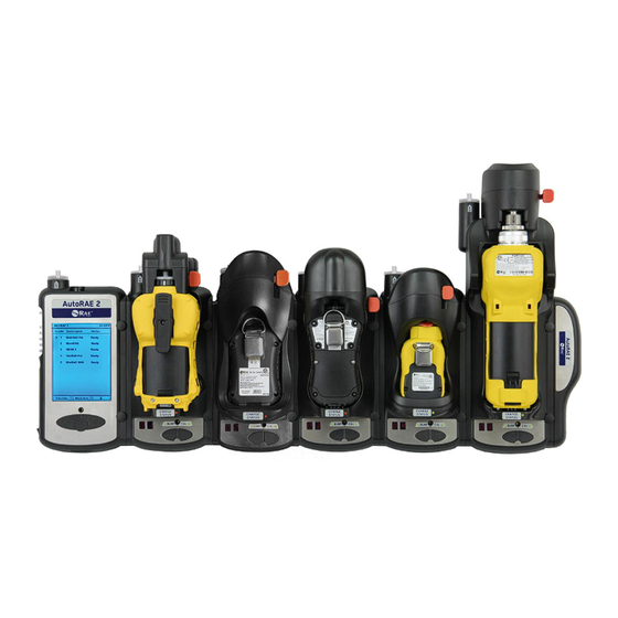
Page 7: Autorae 2 Automatic Test And Calibration System - General Information
Simply cradle the monitor and the system will take care of all calibration, testing, and recharging. The AutoRAE 2 is a flexible, modular system that can be configured to meet your calibration requirements effectively and efficiently. An AutoRAE 2 system can be as... - Page 8 Summary Of Differences Between An AutoRAE 2 Controller-Based System And A Stand-alone Cradle Controller-Based System Standalone Cradle Monitors calibrated simultaneously Up to 10 Number of gas inlets (distinct 5 dedicated gas inlets plus 2 dedicated gas inlets calibration gas cylinders)
-
Page 9: Specifications
2. Specifications Size AutoRAE 2 Controller 5.63" W x 10.43" L x 1.73" H (143 x 265 x 44 mm) MultiRAE Cradle 6.50" W x 12.68" L x 4.37" H (165 x 322 x 111 mm) ToxiRAE Pro Cradle 6.50" W x 11.61" L x 3.91" H (165 x 295 x 99 mm) QRAE 3 Cradle 6.50"... - Page 10 Specifications continued Gas Inlet/Outlet Ports AutoRAE 2 Controller 6 inlets (1 dedicated fresh air inlet and 5 configurable calibration gas inlets); 1 exhaust port Cradle 3 inlets (1 dedicated fresh air inlet and 2 configurable calibration gas inlets); 1 exhaust port...
-
Page 11: Overview
An AutoRAE 2 Cradle can be used on a tabletop (or other flat surface) or mounted on a wall. Wall-mounting instructions are included in this guide. - Page 12 ToxiRAE Pro Cradle Capture mechanism Filter (hidden) Release mechanism Air inlet (hidden) Sensors for testing ToxiRAE Pro LED alarms Exhaust port (not shown) End cap, right 2 gas inlets (not shown) Sensor for USB port testing (not shown) ToxiRAE Pro buzzer DC input from AC...
- Page 13 QRAE 3 Cradle Capture mechanism Filter Release mechanism Air inlet Sensors for testing QRAE 3 LED alarms Exhaust port 2 gas inlets Sensors for testing Sensor for QRAE 3 testing QRAE 3 LED alarms buzzer USB port Charge contacts (not shown) DC input Charging status from AC...
- Page 14 MicroRAE Cradle Capture mechanism Filter Release (hidden) mechanism Air inlet (hidden) Sensors for testing LED alarms Exhaust port (not shown) End cap, right 2 gas inlets (not shown) Sensor for testing buzzer USB port Sensors for testing (not shown) LED alarms DC input Charge contacts from AC...
- Page 15 Handheld PID Cradle Capture mechanism Filter Release mechanism Air inlet Sensors for testing LED alarms Sensor for testing buzzer 2 gas inlets Exhaust port USB port (not shown) DC input Charge contacts from AC adapter Charging status Cal/Status Bump Bump/Status 2-character LED display Extending the Handheld PID Cradle to accommodate an UltraRAE 3000...
- Page 16 End Cap With Ports, All Models 12V DC power Exhaust port Input port ports The USB port has a sliding cover that protects the contacts from contamination when it is not in use. Simply slide the cover over the port.
-
Page 17: Standard Package Contents
000), AutoRAE 2 Cradle for MicroRAE (P/N T02-0503-000), and AutoRAE 2 Cradle for ToxiRAE Pro Monitors (P/N T02-0003-000) are shipped with the following: AutoRAE 2 Cradle for MultiRAE Pumped Monitors, AutoRAE 2 Cradle for QRAE 3 Pumped Monitors, AutoRAE 2 Cradle for Handheld PID (MiniRAE Lite, MiniRAE... -
Page 18: Installing End Caps For Stand-Alone Use
The AutoRAE 2 Cradle is shipped with left and right end caps, which are intended to protect and label the ports on both sides of the AutoRAE 2 Cradle. The one for the “input” side (left end cap) snaps on, while the one on the other side (right end cap) gets slipped into its position and is then secured with two screws (plastic caps are included, to hide the screws). -
Page 19: Powering The Autorae 2 Cradle
AutoRAE 2 Controller, and therefore does not need a separate AC adapter.) The jack for the AC adapter connection is in the recess of the left end cap. Plug the barrel end of the AC adapter into the AutoRAE 2 Cradle and the transformer into an AC outlet. -
Page 20: Preparing For Bump Testing & Calibration
In order to ensure that fresh air is uncontaminated by dust or other materials, use a filter on the AutoRAE 2 Cradle’s fresh air inlet. The inlet is located on the top end, to the left of the locking mechanism. Inspect the filter periodically and replace it as necessary if dirty, damaged, or contaminated. -
Page 21: Connecting An Ac Adapter
6.3. Connecting An AC Adapter The AutoRAE 2 Cradle uses a 12V, 1.25A DC adapter. Plug the barrel end into the port on the side of the AutoRAE 2 Cradle and the transformer end into an AC power source. There is no power switch, so when power is applied to the AC adapter, the AutoRAE 2 Cradle is powered. -
Page 22: Connecting Calibration Gas
In addition, there is a connection labeled “Exhaust,” for venting the gas after it has gone through the AutoRAE 2 Cradle. All three connections are barbed to secure the hoses to them. All gas connections are barbed to secure the hoses to them. - Page 23 This same logic applies to the order of performing a bump test on an instrument that has cross-sensitive sensors. For more information on cross-sensitivities for select sensors, consult RAE Systems Technical Note TN-114.
-
Page 24: Placing A Multirae Monitor In The Cradle
1. Make sure the external filter on the instrument is not dirty or clogged and screwed onto the instrument inlet tightly. 2. Make sure the monitor is either turned off or is in AutoRAE 2 Communications Mode. 3. Place the instrument into the cradle face-down, making sure that it is aligned correctly with the contacts on the AutoRAE 2 Cradle’s charging port. -
Page 25: Placing A Toxirae Pro Monitor In The Cradle
6.6. Placing A ToxiRAE Pro Monitor In The Cradle The ToxiRAE Pro cradle requires one of two different adapters, and each is specific to the type of ToxiRAE Pro. They click into place and can be easily removed, in case you want to use one cradle for bump testing/calibrating/managing different types of ToxiRAE Pro monitors. -
Page 26: Placing A Toxirae Pro Monitor In The Cradle
2. Make sure the external filter on the instrument is not dirty or clogged and screwed onto the instrument inlet tightly. 3. Make sure the monitor is either turned off or is in AutoRAE 2 Communications Mode. 4. Place the instrument into the cradle face-down, making check that it is aligned correctly with the contacts on the AutoRAE 2 Cradle’s charging port. -
Page 27: Placing A Qrae 3 Monitor In The Cradle
1. Make sure the external filter on the instrument is not dirty or clogged and screwed onto the instrument inlet tightly. 2. Make sure the monitor is either turned off or is in AutoRAE 2 Communications Mode. 3. Place the instrument into the cradle face-down, making sure that it is aligned correctly with the contacts on the AutoRAE 2 Cradle’s charging port. - Page 28 6.8. Placing A MicroRAE Monitor In The Cradle 1. Remove the external filter from the instrument. 2. Make sure the monitor is either turned off or is in AutoRAE 2 Communications Mode. 3. Place the instrument into the cradle face-down, making sure that it is aligned correctly with the contacts on the AutoRAE 2 Cradle’s charging port.
-
Page 29: Placing A Handheld Pid Monitor In The Cradle
6.9. Placing A Handheld PID Monitor In The Cradle You must remove the inlet probe before placing a handheld PID instrument (MiniRAE Lite, MiniRAE 3000, ppbRAE 3000, or UltraRAE 3000) into the cradle. If the instrument does not have a Quick Connector (P/N: T02-3301-000) already installed, you must install one. 6.9.1. -
Page 30: Installing The Instrument In The Cradle
1. Remove the inlet probe by pressing down on both sides of the base and releasing the probe. 2. Make sure the monitor is either turned off or is in AutoRAE 2 Communications Mode. 3. Place the instrument into the cradle face-down, making sure that it is aligned correctly with the contacts on the AutoRAE 2 Cradle’s charging port. -
Page 31: Warm-Up
Remove the monitor from the cradle and refer to the information on the instrument display. An instrument to be placed in the cradle can be off or turned on and set for AutoRAE 2 Communications mode. -
Page 32: Performing A Bump Test
(as specified for Bottles 15 and 16 under Gas Config 8; see Section 13.1). 2. Insert an instrument in the AutoRAE 2 Cradle (as described in Section 6.4) and wait for it to warm up (as described in Section 6.5). -
Page 33: Performing A Calibration
Cradle (as specified for Bottles 15 and 16 under Gas Config 8; see Section 12.1). 2. Insert an instrument in the AutoRAE 2 Cradle (as described in Section 6.5) and wait for it to warm up (as described in Section 6.10). -
Page 34: Bump And Cal Error And Status Messages
9. Bump And Cal Error And Status Messages The LEDs labeled “Bump” and “Cal” above the two keys on the AutoRAE 2 Cradle provide information about status during bump and calibration testing. The following table explains the various messages: Status... - Page 35 You may remove the successfully instrument from the Cradle for use or leave it on the Cradle for the next AutoRAE 2 operation or to charge its battery. Calibration failed Off Red (blinking The result has been logged in the slowly) instrument;...
-
Page 36: Charging An Instrument's Battery
Placing an instrument in the cradle and locking it in position allows the instrument’s battery to be charged. When power is applied to the AutoRAE 2 Cradle and the instrument’s battery is charging, the LED glows red. The LED glows green when the battery is fully charged: 11. -
Page 37: Autorae 2 Reports
11.1. AutoRAE 2 Reports After you perform any test on an instrument, the display on the instrument gives a report for each test that has been done. Step through the screens to see results from tests that were performed. For example, on... - Page 38 Select Exit to return the monitor to Normal Measurement Mode.
-
Page 39: Programming A Stand-Alone Autorae 2 Cradle
AutoRAE 2 Cradle connected to a power source, and a USB PC communications cable. 1. Connect a USB cable between a PC with ProRAE Studio II and the AutoRAE 2 Cradle. 2. Make sure the AutoRAE 2 Cradle is on (AC adapter connected and plugged in). - Page 40 9. ProRAE Studio II downloads the AutoRAE 2 Cradle’s configuration data (a progress bar is shown during downloading). The AutoRAE 2 Cradle’s data is shown, including its Model Number and Serial Number: Click “Clock Information” to check or set the date and time:...
- Page 41 If you want to synchronize the date and time on the AutoRAE 2 Cradle with the time on the PC, click the box labeled “Sync with PC.”...
-
Page 42: Gas Inlet Configuration Settings
12.1. Gas Inlet Configuration Settings “Gas Bottle Information” tells the AutoRAE 2 what kind of gas is supplied to each gas inlet. The “Gas Bottle Information” section includes configuration parameter settings for the two AutoRAE 2 Cradle gas inlets including gas types, concentrations, concentration units, purge time, and soak time for gas cylinders connected to each gas inlet. - Page 43 When you click on Gas Config 8, the two gas bottles (Gas Inlet 15 and Gas Inlet 16) are shown:...
- Page 44 Gas Config 8 covers settings for two cylinders of gas – Gas Bottle 15 and Gas Bottle 16. Gas Bottle 15 and Gas Bottle 16 correspond to gas inlets 1 and 2, respectively, on the side of the AutoRAE 2 Cradle. Number of gases in the...
-
Page 45: Selectable Gas Index Values For Gas Config 8
12.2. Selectable Gas Index Values For Gas Config 8 You can use the pull-down menus to select Gas Index values for the two bottles (Gas Bottle 15 or Gas Bottle 16) to be used for Gas Config 8. Supported gases include: 1 - CO 9 - HCl 17 - CH... -
Page 46: Concentration [Value]
12.4. Concentration [Value] You can set the concentration by double-clicking in the respective gas concentration box and then typing in the concentration value. 12.5. Concentration Unit When you pull down the Concentration Unit menu, select the desired gas concentration units (there are other types of units). %LEL %VOL 12.6. -
Page 47: Uploading Settings To The Autorae 2 Cradle
12.8. Uploading Settings To The AutoRAE 2 Cradle 1. When you are done setting the Gas Configs, upload them to the AutoRAE 2 cradle by clicking on the “Upload all settings to the instrument” icon: 2. A dialog box appears: ... -
Page 48: Recalling Stored Settings
When you are done programming and have saved the settings, do the following: 1. Exit ProRAE Studio II. 2. Disconnect the USB cable between the PC and the AutoRAE 2 Cradle. 3. Press the “Bump” key on the AutoRAE 2 Cradle (the display changes from “PC” to the active gas configuration, G8). -
Page 49: Upgrading Firmware On The Autorae 2 Cradle
Upgrades to a stand-alone AutoRAE 2 Cradle’s firmware can be loaded into the AutoRAE 2 Cradle using ProRAE Studio II software running on a PC. If the Cradle (or multiple Cradles) is attached to an AutoRAE 2 Controller, follow the AutoRAE 2 Controller Firmware Upgrade instructions on page 99. - Page 50 Select the AutoRAE 2 Cradle. 10. Click “Select.” 11. The three options on the left are “Setup,” “Firmware,” and “Tool.” Click “Firmware.”...
- Page 51 16. Click “Start.” 17. The firmware is uploaded to the AutoRAE 2 Cradle. 18. Exit PC Communications mode on the AutoRAE 2 Cradle by pressing “Bump.” The display should now show “G8.” 19. Exit ProRAE Studio II on the PC.
-
Page 52: Using A Stand-Alone Autorae 2 Cradle For Datalog Transfer, Monitor Configuration, And Firmware Upgrades
USB port on a stand- alone AutoRAE 2 Cradle. Use the included USB cable to connect the AutoRAE 2 Cradle to a computer running ProRAE Studio II (version 1.10.0 or higher). Follow the... -
Page 53: Overview
AUTORAE 2 CONTROLLER-BASED SYSTEM 15. Overview The AutoRAE 2 Controller turns the AutoRAE 2 into a powerful, networked docking station that can support up to 10 monitors at a time and accommodate up to five distinct gas sources for multi-sensor calibration and bump testing. -
Page 54: Standard Package Contents
The AutoRAE 2 Controller has sliding covers to protect its USB and Ethernet ports from contamination when they are not in use. Simply slide their respective covers over them. 15.1. Standard Package Contents The AutoRAE 2 Controller (P/N T02-0107-000) is shipped with the following: ... -
Page 55: Operation Of An Autorae 2 Controller-Based System
Command Language 5 or 5E) for direct printing, and has a standard SD card on which data are stored. When one or more AutoRAE 2 Cradles are attached to the AutoRAE 2 Controller, the AutoRAE 2 controller acts as the “command center” for the system. The Controller powers the entire system, manages all the configuration settings, and its built-in pump and valves control the gas flow. -
Page 56: Setting Up An Autorae 2 Controller-Based System
17. Setting Up an AutoRAE 2 Controller-based System A single AutoRAE 2 Controller can connect with up to 10 AutoRAE 2 Cradles (these can be all of one kind, or mixed types). The Terminal Adapter must be connected to the final (rightmost) AutoRAE 2 Cradle. -
Page 57: Installing Batteries For The Real-Time Clock
17.1. Installing Batteries For The Real-Time Clock The AutoRAE 2 Controller has an internal real-time clock (RTC), which is set via ProRAE Studio II. A small button cell is soldered to the main board to keep the clock running when power is removed from the system (it is recharged when power is connected). -
Page 58: Attaching An External Filter
In order to ensure that fresh air is uncontaminated by dust or other materials, use a filter on the AutoRAE 2 Controller’s fresh air inlet. The inlet is located at the top end on the left side. Inspect the filter periodically and replace it as necessary if it is dirty, damaged, or contaminated. -
Page 59: Powering An Autorae 2 Controller-Based System
An AutoRAE 2 Controller-based system is powered by its 12V, 7.5A AC adapter. The jack for the AC adapter connection is in the recess on the left side of the AutoRAE 2 Controller, next to the power on/off switch. Plug the barrel end of the AC adapter into the AutoRAE 2 and the transformer into an AC outlet. -
Page 60: Operating A Controller And Attached Cradles
When An AutoRAE 2 Controller is attached to one or more AutoRAE 2 Cradles, the buttons on the AutoRAE 2 Cradles are only used to initiate a bump test or calibration. The two-character LED displays on each Cradle show the ID number for the respective Cradle. - Page 61 If the Terminal Adapter Check fails, make sure the Terminal Adapter is connected to the last AutoRAE 2 Cradle, and that all of the AutoRAE Cradles in the system are firmly connected. Try restarting the system. If everything is connected but the test fails again,...
-
Page 62: User Interface
If all tests pass, then this screen is displayed, indicating that the AutoRAE 2 system is ready for use: If there are instruments in the cradles, their warm-up process starts automatically as soon as their respective cradle has been powered up and identified by the AutoRAE 2 Controller. -
Page 63: Display Status Messages And Color Coding
19.5. Display Status Messages and Color Coding The AutoRAE 2 Controller has a color display, so colors are used to indicate status in different categories of information. Status Color Explanation Pass Green 1. All sensors and alarms passed bump test. -
Page 64: Testing
(whether an SD card is present, whether it is full or nearing full capacity, etc.), a test of each attached AutoRAE 2 Cradle, and then a test of any instruments that are in the cradles. Bump testing and calibration can only take place on an instrument if its tests are passed, including compatibility between the gas settings in the AutoRAE 2 Controller and the instrument. - Page 65 If there is a mismatch, check the instrument’s settings in Programming Mode, as well as the settings programmed for the AutoRAE 2 via ProRAE Studio II. If all instruments in the cradles warm up and all test without errors or incompatibilities,...
-
Page 66: Preparing For Bump Testing & Calibration
The AutoRAE 2 cannot operate without an SD card in its slot. Note: If no SD card is in the slot when the AutoRAE 2 Controller is turned on, or the SD is locked, or if the SD card is removed during operation, the display shows this message:... - Page 67 AutoRAE 2 Controller is running. This may damage the SD card or corrupt its data. If the SD card is locked, the error message shown above is displayed. The AutoRAE 2 Controller cannot write data to a locked SD card. Remove the SD card and unlock it by moving the lock tab upward;...
-
Page 68: Installing An Sd Card
20.1.1. Installing An SD Card 1. Use a 2.0-size hex wrench to loosen and remove the screw holding the cover on the SD card port. 2. Slide the door down so that the port is visible. 3. Press the SD card into the slot with the angled notch on the right. Press until it locks into place, making a “click”... -
Page 69: Connecting Calibration Gas
Connect cylinders of calibration gas to the inlet ports labeled “Gases” on the left side of the AutoRAE 2 Controller. Make sure that they are connected to the correct inlet, as defined in Gas Bottle settings described in Section 21.1. -
Page 70: Placing Monitors In Cradles
22. 20.4. Performing A Bump Test The AutoRAE 2 Controller lets you perform bump tests on individual instruments or all instruments that are cradled. A bump test can be initiated by pressing a Bump button on the Cradle or selecting a Bump Test via the AutoRAE 2 Controller menus. - Page 71 Note: A grayed-out box indicates that it cannot be selected. When you check “Bump All,” the “Bump All” checkbox and all of the other checkboxes for identified instruments are checked.
- Page 72 You can also select individual instruments for bump testing. Press [N/-] to scroll down the list. Press [Y/+] to toggle the selection between checked and unchecked. After you have made your selection(s), press [MODE] to start the bump test.. Press [N/-] to select “Exit,”...
- Page 73 If there is a mismatch between sensors and calibration gas settings, then this message is shown. The bump test countdown still proceeds. The sensors that do match the calibration gas settings will be bump tested.
-
Page 74: Interrupting A Bump Test
20.4.1. Interrupting A Bump Test Pressing the Abort button during a bump test suspends the test, and this message appears on the AutoRAE 2 Controller’s display: Removing an instrument from the cradle during a bump test interrupts it and results in the following message: Press [N/-] to abort the bump test. - Page 75 When all bump tests are complete, the display shows results: This chart shows what the results mean: Result Description Pass All sensors passed successfully Pass ? All sensors that were tested passed successfully, but some sensors were not tested. Fail The instrument failed one or more tests The instrument was not tested Select a menu item, and then follow through its screens.
-
Page 77: Performing Calibration
20.5. Performing Calibration The AutoRAE 2 Controller lets you perform calibration on individual instruments or all instruments that are cradled. A calibration can be initiated by pressing a Cal button on the Cradle or selecting a Calibration via the AutoRAE 2 Controller menus. - Page 78 You can select “Calibrate All” or individual instruments. To select “Calibrate All,” press [Y/+] to check the “Calibrate All” box. You can also select individual instruments for calibration. Press [N/-] to scroll down the list. Press [Y/+] to toggle the selection between checked and unchecked. ...
-
Page 79: Interrupting A Calibration
A screen shows the instruments to be calibrated and begins a countdown. All calibrations are then performed automatically. 20.5.1. Interrupting A Calibration Releasing an instrument from an AutoRAE 2 Cradle or otherwise interrupting a calibration suspends the test, and this message appears on the AutoRAE 2 Controller’s display:... - Page 80 If you remove the instrument, calibration cannot resume. You must abort the calibration and restart it. Press [N/-] to abort the calibration. This screen is displayed. After calibration is complete, the AutoRAE 2 controller shows status:...
-
Page 81: Direct Bump Testing And Calibrating Via The Cradles' Buttons
20.6. Direct Bump Testing And Calibrating Via The Cradles’ Buttons When multiple AutoRAE 2 Cradles are connected to a Controller, they can still be used individually to perform a bump test or calibration. 1. Place one or more instruments in the Cradles. - Page 82 When it reaches zero, the bump and calibrations are initiated. You can quit during this time (press [N/-]). The instruments will undergo a bump test or calibration using parameters stored in the attached AutoRAE 2 Controller. (A stand-alone AutoRAE 2 Cradle uses the configuration stored in its internal configuration.)
-
Page 83: Configuration Settings
20.7. Configuration Settings In addition to showing status of the most recent bump and calibration testing, the main screen provides access to check settings and change the password. At the main screen, press [Y/+], which selects “Function”:... -
Page 84: Settings
20.8. Settings At the main screen, press [Y/+], which selects “Function”: A menu is shown. Press [N/-] until “Settings” is selected (the triangle to the right of the name indicates the selection): Click [Y/+] to enter Settings. - Page 85 A password screen is shown. You must input a password for Advanced access. (A Basic access level is reached with an incorrect password.) The default value is “0000” (four zeroes). Press [Y/+] to increase a value (0 through 9). ...
- Page 86 If you have entered an incorrect password again, then you access the Basic settings, which provides read-only information about the gases configured for each gas inlet: To navigate between the settings types in Advanced mode, press [N/-]. To select, press [Y/+].
-
Page 87: Gas Settings
20.8.1. Gas Settings Gas Settings consists of read-only screens that show the gas configuration for each of the five gas inlets. To advance through the settings, press [N/-]. The current screen is highlighted by the empty circle in the series of circles representing the five inlets. To exit from Gas Settings and return to the Settings screen, press [MODE]. -
Page 88: System Settings
In Advanced Mode, you are allowed to make changes to the system’s settings. System Settings (Advanced mode only) allow you to access the following: Controller Information This is read-only information about the AutoRAE 2 Controller: Model Serial Number ... -
Page 89: Network Settings
Press [N/-] to advance to the next digit. Press [MODE] to save the new password. Action after Bump Failed You can select the action performed by the AutoRAE 2 if a bump test fails. Your options are: Calibration if Bump Test Fail ... - Page 90 DHCP Enable/Disable You can enable or disable DHCP (Dynamic Host Configuration Protocol) at this screen. With DHCP Enable/Disable highlighted in the Network Settings menu, press [Y/+] to access the Enable and Disable options. Note: The currently operational option is shown at the top in a box.
-
Page 91: Programming An Autorae 2 Controller-Based System On The Computer
4. Select “Administrator” and input the password (the default is “rae”). 5. Click “Detect the instruments automatically” (the magnifying glass icon with the letter “A” in it). After a few seconds, the AutoRAE 2 Controller is found and it is shown, along with its firmware version, serial number, COM port: 6. - Page 92 ProRAE Studio II downloads the AutoRAE 2 Controller and all attached AutoRAE 2 Cradles’ configuration data (a progress bar is shown during downloading). Note: The AutoRAE 2 Controller’s display shows this message while it is connected and communicating with a PC running ProRAE Studio II: Communicating with Computer.
- Page 93 Double-click the AutoRAE 2 Controller to check its settings and to program it. The Setup/Firmware screen appears: Notice that it shows the AutoRAE 2 controller is active, both in the status bar along the bottom and in the hierarchy at the top of the screen.
- Page 94 Click “Setup” to begin programming. This setup screen is shown: Click “Clock Information” to check or set the time: If you want to synchronize the date and time on the AutoRAE 2 Controller with the date and time on the PC, click the box labeled “Sync with PC.”...
- Page 95 Set the password for access to the AutoRAE 2. Note: The default value is “0000.”...
-
Page 96: Gas Inlet Settings
The “Gas Inlet Information” section includes configuration parameter settings for the five gas inlets on the AutoRAE 2 Controller. For each “Gas Inlet,” you can view and set the gas type, concentration, concentration unit, purge time, and soak time. You can modify these values and upload them to your AutoRAE 2 or download the values currently programmed into the AutoRAE 2 to ProRAE Studio II. -
Page 97: Gas Lot Number
be zero (0). This allows you to effectively remove the corresponding inlet from calibrations and bump testing. 21.2.2. Gas Lot Number Fill in the numbers to correspond to the lot number printed on the gas cylinder. This will be included in any test and calibration certificates generated while bump testing or calibrating instruments using this gas. -
Page 98: Concentration Unit
21.2.7. Concentration Unit When you pull down the Concentration Unit menu, select the desired gas concentration unit (there are other types of units). mg/m ug/m %LEL %VOL 21.2.8. Purge Time (Sec.) Type to set the number of seconds for the system to purge with fresh air after performing a bump test or calibration. -
Page 99: Uploading Settings To The Autorae 2
(Gas Bottle 1 through 5), and then click the “Get Current Content Settings” button: If you want to upload a single set of Gas Bottle settings to the AutoRAE 2, click the name (Gas Bottle 1 through 5), and then click the “Set Current Content Settings” button: 21.5. -
Page 100: Recalling Stored Settings
If you have previously stored settings in a separate file, you can call them up so that you can modify them and/or apply them to the AutoRAE 2 system. This feature is especially useful if you have multiple individual systems to which similar settings need to be populated. -
Page 101: Updating Firmware On The Autorae 2 Controller
Updates to the AutoRAE 2 Controller’s firmware may be produced, and these can be loaded into the AutoRAE 2 Controller using ProRAE Studio II software running on a PC. Download firmware from the RAE Systems web site or from a CD-ROM. - Page 102 Select the AutoRAE 2 Controller. Click “Select.” 10. The AutoRAE 2 Controller is shown, along with its serial number. Click “Firmware.” 11. Double-click on the AutoRAE 2 Controller’s icon, and this screen appears: The options on the left are “Setup,” “Firmware,” and “Tool.”...
- Page 103 12. Click the “Firmware” button. Now this window appears: 13. Where it says “RFP File:” click the button labeled “…” and locate the firmware file with the “.rfp” suffix. Then click “Upload Firmware.” 14. Click the box labeled “Upgrade for specific SN, and then pull down the menu and select the serial number that matches the one shown in the upper right side of the window.
- Page 104 18. The firmware file is uploaded to the AutoRAE 2 Controller’s SD card, and the AutoRAE 2 Controller uploads the firmware to the AutoRAE 2 Controller or cradle, respectively. 19. Exit ProRAE Studio II on the PC. 20. Disconnect the USB cable.
-
Page 105: Transferring Autorae 2 Controller Data To A Computer
Note: You can get reports with any level of access privileges. 4. Click “Detect the instruments automatically” (the magnifying glass icon with the letter “A” in it). After a few seconds, the AutoRAE 2 Controller is found and it is shown, along with its firmware version, serial number, COM port:... - Page 106 6. This screen appears: 7. Expand either Online or Offline to view Instruments. 8. Click “Instruments.”...
- Page 107 Instruments that have been bump tested and calibrated on a system with this AutoRAE 2 Controller are shown:...
- Page 108 9. Double-click on an instrument to view its reports: The Reports window opens for this instrument:...
- Page 109 10. Click “Reports,” and the window changes: 11. Click the “Download All Reports” button: If there are no reports, an alert appears: If there are reports, then they are downloaded and put in a list in the left column: If the list is long, you can change the order so the list order is reversed (from 001, 002, 003, etc., to 003, 002, 001, etc.).
-
Page 110: Exporting Reports
13. When you are done, click “OK.” Caution! Once you change the name of the report and click “OK,” the change cannot be undone. If you want to change the report’s name back to its original, you must do it by typing in the information. -
Page 111: Saving A Configuration Upon Exit
23.2. Saving A Configuration Upon Exit When you close ProRAE Studio II after you have downloaded reports or made changes, you will see this prompt: If you do not want to save changes to the configuration, click “No.” If you want to save the changes, click “Yes.”... -
Page 112: Wireless Operation
Internet Adapter (or equivalent) 24.1. Part One: Configure The AutoRAE 2 Network Interface 1. Connect an Ethernet cable between the PC and the AutoRAE 2 Controller. 2. On the AutoRAE 2 Controller, enter Function and then Settings choose “Select.” 3. When the dialog box appears, input your password. Select “Done.”... -
Page 113: Part Two: Configure The Wifi Adapter & Test The Network
Figure 2 for connection to AutoRAE2. Figure 2. Manually Set PC network properties for connection to AutoRAE 2. 8. Run ProRAE Studio II. The program should be able to detect the AutoRAE 2 Controller via the Ethernet cable and communicate with the AutoRAE 2 Controller normally. - Page 114 1. Keep all the network settings that you provided in Part One. Disconnect and remove the Ethernet cable. 2. Connect a Wi-Fi Internet Adapter (the Netgear WNCE2001 NetGear Universal Wi-Fi Internet Adapter is recommended) to the PC’s network port using the Ethernet cable shipped with the WiFi Internet Adapter.
- Page 115 Figure 4. Select a wireless network. (This example shows all available wireless networks within range. Your choices will be different.) Figure 5. Enter a password to access the selected wireless network.
- Page 116 6. Exit the WiFi Internet Adapter setup. Unplug the Ethernet cable between the WiFi Internet Adapter and the PC, and connect it to the AutoRAE 2 Controller. 7. Restart the AutoRAE 2 Controller. 8. Disable the PC’s Ethernet port.
- Page 117 9. Close the Windows Properties dialog box and wait for a few seconds. The PC will wirelessly connect to the AutoRAE 2 Controller. 10. Run ProRAE Studio II, which should be able to detect the AutoRAE 2 Controller via WiFi connection and communicate with the AutoRAE 2 Controller.
-
Page 118: Wall Mounting A Controller & Cradles
25. Wall Mounting A Controller & Cradles The AutoRAE 2 can be used on a flat surface, or it can be mounted on a wall. This requires drilling holes into the wall and inserting screws to hold the AutoRAE 2. -
Page 119: Transferring Bump And Calibration Data
Once all the AutoRAE 2 units have been slid onto the rails, press them together, insert the screws to secure them to each other, and then place the plastic caps over the screws. Refer to page 54 for assembly details. -
Page 120: Technical Support
28. Technical Support To contact RAE Systems Technical Support: Monday through Friday, 7:00AM to 5:00PM Pacific (US) Time Phone (toll-free): +1 877-723-2878 Phone: +1 408-952-8200 Fax: +1 408-952-8480 Email: RAE-tech@honeywell.com 29. RAE Systems Contacts RAE Systems by Honeywell World Headquarters 3775 N.
Need help?
Do you have a question about the AutoRAE 2 and is the answer not in the manual?
Questions and answers