
Subscribe to Our Youtube Channel
Related Manuals for GE Mooney Flowgrid


Summary of Contents for GE Mooney Flowgrid
- Page 1 GE Oil & Gas Mooney* Flowgrid* Regulator Instruction Manual GE Data Classification : Public...
- Page 2 SPECIFIC REFERENCE INFORMATION IN ADDITION TO THE CUSTOMER/OPERATOR’S NORMAL OPERATION AND MAINTENANCE PROCEDURES. SINCE OPERATION AND MAINTENANCE PHILOSOPHIES VARY, GE (GENERAL ELECTRIC COMPANY AND ITS SUBSIDIARIES AND AFFILIATES) DOES NOT ATTEMPT TO DICTATE SPECIFIC PROCEDURES, BUT TO PROVIDE BASIC LIMITATIONS AND REQUIREMENTS CREATED BY THE TYPE OF EQUIPMENT PROVIDED.
-
Page 3: Table Of Contents
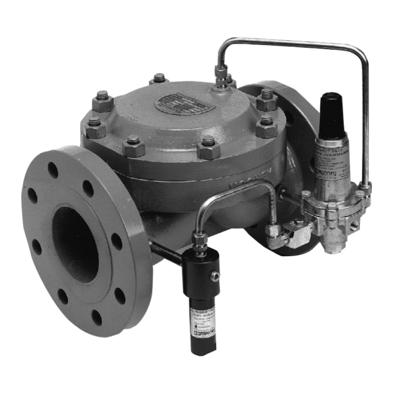
Scope This manual provides installation, operation, and maintenance instructions for the Mooney Flowgrid regulator. Instructions for the Mooney Series 20 pilot and Mooney noise controller will be found in a separate manual. Table of Contents Product Description ................1 Piping Details ..................7 Regulator Markings ................ - Page 4 Reverse flow by changing pilot connections and reversing spring case. Figure 1 - Flowgrid Parts The fabric-reinforced diaphragm (4) is the main All Mooney Flowgrid regulators have six main parts (excluding bolting and O-rings); the body, throttle plate, working part of the Flowgrid regulator. The diaphragm spacer, diaphragm, main spring, and spring case.
-
Page 5: Regulator Markings
Maximum allowable operating pressure differential (psig)/(bar) Max Temp Maximum operating temperature in degrees Fahrenheit Bolt Torq Recommended bolt torque for spring Ft-lbs/Nm case in foot pounds © 2015 General Electric Company. All rights reserved. Mooney Flowgrid Regulator Instruction Manual | 3... -
Page 6: Principles Of Operation
Pilot Outlet Pilot Outlet Connection Connection Inlet Inlet Outlet Outlet Figure 7 - Back Pressure Configuration Partially Open Figure 6 - Back Pressure Configuration Fully Closed 4 | GE Oil & Gas © 2015 General Electric Company. All rights reserved. -
Page 7: Hydrostatic Testing
C. Outlet of “Tee” connected to outlet connection on area cut out leaving the outer sealing regulator surface (see below). This area removed © 2015 General Electric Company. All rights reserved. Mooney Flowgrid Regulator Instruction Manual | 5... -
Page 8: Installation
Reassemble regulator (refer to the Maintenance section of this manual for Disassembly and Assembly procedures) and pressurize with air to check for leaks prior to putting the regulator in service. 6 | GE Oil & Gas © 2015 General Electric Company. All rights reserved. -
Page 9: Piping Details
6. Outlet port of Series 20 Pilot connected to Outlet connection of Flowgrid regulator. 7. Pilot cartridge in PRV mode (pressure reducing) BPV (back pressure/relief) mode. © 2015 General Electric Company. All rights reserved. Mooney Flowgrid Regulator Instruction Manual | 7... - Page 10 9. Pilot cartridge in PRV mode (pressure reducing) BPV (back pressure/relief) mode. NOTE: Dual port regulators in 1” - 8” sizes have been discontinued. Schematics for reference only. 8 | GE Oil & Gas © 2015 General Electric Company. All rights reserved.
- Page 11 12. Sense line connecting Sense port on Series 20 Pilot to downstream piping. 13. Outlet port of Series 20 Pilot connected to Outlet connection of Flowgrid regulator. 14. Pilot cartridge in PRV mode. © 2015 General Electric Company. All rights reserved. Mooney Flowgrid Regulator Instruction Manual | 9...
- Page 12 NOTE: In a working Monitor system with less than 25 psig (1.72 bar) differential across the second stage regulator the pilot supply (11) may be connected to the piping upstream of the first stage regulator. This will improve the shutoff of the second stage regulator. 10 | GE Oil & Gas © 2015 General Electric Company. All rights reserved.
-
Page 13: Start-Up And Operation
9. Slowly adjust the pilot spring setting until the desired gain (widen the proportional band), less sensitivity, upstream pressure (relief setting) is achieved. and faster closing speeds. © 2015 General Electric Company. All rights reserved. Mooney Flowgrid Regulator Instruction Manual | 11... - Page 14 This applies to the Series 20 Pilot only; consult with GE for applicability to other manufacturer’s pilots. Figure 9 - Standby Monitor Schematic 12 | GE Oil & Gas...
-
Page 15: Maintenance
Be certain that the injury and property damage. name plates are updated to accurately indicate any field changes in equipment, materials, service condi- tions, or pressure settings. © 2015 General Electric Company. All rights reserved. Mooney Flowgrid Regulator Instruction Manual | 13... - Page 16 Grade 7 or ASTM Grade B7 rating. surface of adjacent parts must also be smooth to prevent leakage. Reconnect the pilot system. Follow Start up procedures when returning to operation. 14 | GE Oil & Gas © 2015 General Electric Company. All rights reserved.
-
Page 17: Troubleshooting
Pilot diaphragm rupture if (BPV relief pilot) Blockage of pilot orifice Blockage can be caused by debris, hydrates, freezing or damage to the component involved. © 2015 General Electric Company. All rights reserved. Mooney Flowgrid Regulator Instruction Manual | 15... - Page 18 16 | GE Oil & Gas © 2015 General Electric Company. All rights reserved.
-
Page 19: Warranty
8:00 AM to 4:30 PM MST Monday through Friday. Limited after hours support is also available. Complete product specifications, parts lists, and flow calculation software is available on our web site www.geoilandgas.com/valves. © 2015 General Electric Company. All rights reserved. Mooney Flowgrid Regulator Instruction Manual | 17... - Page 20 +91-11-5-1659635 Fax: +1-281-671-1735 Jacksonville, Florida Phone: +1-844-VALVE-GE www.geoilandgas.com/valves *Denotes a trademark of the General Electric Company. Other company names and product names used in this document are the registered trademarks or trademarks of their respective owners. ©2015 General Electric Company. All rights reserved.
Need help?
Do you have a question about the Mooney Flowgrid and is the answer not in the manual?
Questions and answers